1
Measurement of Range of Motion and Muscle Length
Background, History, and Basic Principles
Historically, early reports on procedures for the examination of range of motion (ROM) suggested using visual approximation.1 In fact, as late as the 1960s, the initial edition (1965) of a text for measuring joint ROM published by the American Academy of Orthopaedic Surgeons (AAOS)2 suggested that visual estimation is as good as, or better than, goniometric measurement. This opinion was shared by Rowe,3 who suggested that visual estimation was especially important when bony landmarks were difficult to see or to palpate. In contrast, Moore4 and Salter5 stated that goniometer measurements are more reliable than visual estimates.
Disagreement exists among studies that have objectively examined the value of visual estimation compared with the goniometer. Studies by both Awan et al6 and Hayes et al7 reported that little difference existed between visual inspection and a goniometer for the measurement of shoulder ROM. However, upon further examination of the reliability coefficients, intrarater reliability ranged from .59 to .71 for visual inspection and from .53 to .71 for the use of the goniometer. In other words, the testers who collected the data were not all that accurate, irrespective of whether or not a goniometer was used. Williams and Callaghan8 also reported that no significant difference existed between visual estimation and the goniometer in the measurement of shoulder flexion. However, the design of this study, in which three testers measured one subject twice while the subject held the arm elevated, calls into question the rigor of this investigation.
In contrast, Watkins et al9 reported that reliability of the measurement of knee flexion was greater when a goniometer rather than visual estimation was used. Two studies in which the lead author was Youdas10,11 reported that the use of instruments to examine the ankle and the cervical spine resulted in more accurate measurements than were obtained through visual estimation. In a systematic review of the interrater reliability of measurements of passive upper extremity motion, van de Pol et al12 reported, “In general, measuring passive physiological range of motion using instruments, such as goniometers or inclinometers, resulted in higher reliability than using vision.” Given the research suggesting objective measurement is more accurate than visual examination for the measurement of joint ROM, and the demand for data documenting improved patient outcomes, accurate and standardized measurements are of utmost importance.
The purpose of this chapter is to lay the groundwork for standardized measurement of ROM and muscle length. To this end, the chapter specifies the difference between joint ROM and muscle length and presents basic but important information on kinematics (including the definitions of arthrokinematics and osteokinematics). Additionally, background information and the history of a variety of measurement techniques, related both to joint ROM and to muscle length testing, are provided. Finally, suggested procedures for standardized measurement are presented. After reading this chapter, the reader will have gained general information on the measurement of ROM and muscle length, which serves as the basis for performance of the more specific measurement techniques presented in subsequent chapters.
Joint Range of Motion Versus Muscle Length
Joint ROM is an integral part of human movement. In order for an individual to move efficiently and with minimal effort, full ROM across the joints is imperative. In addition, appropriate ROM allows the joints to adapt more easily to stresses imposed on the body and decreases the potential for injury. Full ROM across a joint is dependent on two components: joint ROM and muscle length.13 Joint ROM, the motion available at any single joint, is influenced by associated bony structure and physiologic characteristics of the connective tissue surrounding the joint. Important connective tissue that limits joint ROM includes ligaments and joint capsules.14
Muscle length refers to the ability of a muscle crossing the joint to lengthen, allowing one joint or a series of joints to move through the available ROM. The terms muscle length and flexibility often are used synonymously to describe the ability of a muscle to be lengthened to the end of the ROM. In this book, the term muscle length is used to refer to the end of the range of the muscle across the joint.13
According to Kendall et al15 “For muscles that pass over one joint only, the range of motion and range of muscle length will measure the same. … For muscles that pass over two or more joints, the normal range of muscle length will be less than the total range of motion of the joints over which the muscle passes.” Therefore, if the goal is to measure joint ROM of a joint in which a two-joint muscle is involved, the second joint should be placed in a shortened position. If the goal is to measure muscle length, the muscle should be placed in an elongated position across all joints affected, and a measurement should be taken.15
An example that illustrates the difference between ROM and range of muscle length is the measurement of knee flexion. To measure knee flexion joint motion, the hip should be flexed (the patient is supine) to put the rectus femoris muscle in a shortened position and to allow full joint motion at the knee (illustrated in Chapter 12, Figs. 12-8–12-11). When muscle length of the rectus femoris muscle (a two-joint muscle) is measured, the patient is placed in the prone position, which extends the hip and lengthens the rectus femoris muscle (described in Chapter 14, Figs. 14-13–14-15).
Kinematics
Neumann16 defines kinematics as “a branch of mechanics that describes the motion of a body without regard to the forces or torques that may produce the motion.” In other words, kinematics describes human movement and ignores the cause of the motion (e.g., forces, momentum, energy). This description of motion may include movement of the center of gravity of the body or movement of the extremities, or it may pertain to motion specific to one joint. Kinematics can be subcategorized into specific movements, referred to as arthrokinematics and osteokinematics. To more fully understand kinematics as it relates to measurement of range of joint motion and muscle length, clarification of the terms arthrokinematics and osteokinematics is necessary.
Arthrokinematics
Arthrokinematics refers to actual movements of the joint surfaces in relation to one another. In addition to movement of the lever arm of the bone during ROM activities, the articulating ends of the bone roll, slide (or glide), or spin on each other. Roll is a rotary motion that occurs when new points on one joint surface come in contact with new points on a second joint surface. Slide is a translatory motion that occurs when one joint surface glides across a second surface, so that the same point on one surface is continually in contact with new points on the second surface. A rolling surface usually occurs with a concurrent, oppositely directed slide. Spinning occurs during joint rotation when the longitudinal axis of long bones interacts at a right angle to the articular joint surface. An example is medial and lateral rotation of the shoulder joint when the humerus is abducted to 90 degrees.16 Although arthrokinematic motion is vital for normal ROM, this textbook does not address the measurement or grading of this type of motion.
Osteokinematics
The quality and degree of motion actually observed in the bony lever arm is called osteokinematic motion. Osteokinematic motion is movement of the whole bone that results from rolling and sliding (arthrokinematics) between the articulating surfaces that compose the joint measured.16 For example, when the arm is raised overhead, the bony lever arm (the humerus) moving overhead is the osteokinematic motion. However, for this motion to occur, the head of the humerus must roll and slide on the glenoid fossa (arthrokinematic motion). In most cases, osteokinematic motion is the actual motion that is measured; this type of motion is the focus of this textbook.
Osteokinematic descriptions of movement follow a generalized system that is based on definitions of planes of movement around axes of rotation. For effective discussion of planes of motion and axes of movement, a reference point is required, a point referred to as the anatomical position. This reference point (anatomical position) is defined as “standing erect with the head, toes, and palms of the hands facing forward and with the fingers extended.”17 When ROM at a joint is measured, the starting position is typically the anatomical position. Figs. 1-1 to 1-4 all show the model standing in the anatomical position.
Osteokinematic movement may be described as occurring in one of three imaginary planes of the body, arranged perpendicular to each other, with the axes of each plane intersecting the center of gravity of the body. These imaginary planes are referred to as the cardinal planes of the body. It should be emphasized that human motion is not limited to movement in these cardinal planes, but that this system of planes of movement around axes of rotation provides a simple method for describing ROM and muscle length.16
Sagittal Plane
The sagittal plane is a vertical plane that divides the body into right and left sides (Fig. 1-1). Photographically, this is a side view. Joint movement in the sagittal plane occurs around a line perpendicular to the plane that is referred to as the medial-lateral axis. The osteokinematic motions that occur in the sagittal plane are flexion and extension16 (Fig. 1-2). Gray’s Anatomy defines flexion as occurring “when the angle between two bones is decreased.”18 In other words, during flexion, two bony levers move around the joint axis so that the two levers approach each other. Flexion at the ankle is given a special term, with approximation of the plantar surface of the foot and the leg in the sagittal plane referred to as plantarflexion.
Extension is the opposite of flexion. It occurs when the two bony levers move away from each other, and it is defined as “the act of straightening a limb,” which “occurs when the angle between the bones is increased.”18 Hyperextension is defined as extension beyond the normal anatomical ROM. Dorsiflexion of the foot at the ankle in the sagittal plane is the opposite of plantarflexion.


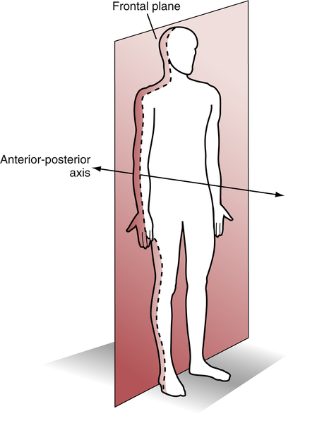
Frontal Plane
The frontal (or coronal) plane is a vertical plane that divides the body into anterior (ventral, or front) and posterior (dorsal, or back) halves (Fig. 1-3). Photographically, this is a front view. Joint movement in the frontal plane occurs around a line perpendicular to the plane that is referred to as the anterior-posterior axis. The osteokinematic motions that occur in the frontal plane consist of abduction, adduction, and lateral flexion of the spine16 (see Fig. 1-2). Abduction is defined as occurring “when a limb is moved away from the midsagittal plane, or when the fingers or toes are moved away from the median longitudinal axis of the hand or foot.”18 Abduction of the wrist is often referred to as radial deviation. The median longitudinal axis of the hand is the third metacarpal, and for the foot, this axis is the second metatarsal. An exception to this definition is abduction that takes place at the carpometacarpal (CMC) joint of the thumb, which is defined as “that action by which the thumb is elevated anterior to the palm.”18 Therefore abduction at the CMC joint actually takes place in the sagittal plane.
Adduction is the opposite of abduction and “occurs when a limb is moved toward or beyond the midsagittal plane, or when the fingers or toes are moved toward the median longitudinal axis of the hand or foot.”18 Adduction of the wrist is often referred to as ulnar deviation. At the CMC joint of the thumb, adduction is moving the thumb posteriorly toward the palm (sagittal plane movement).

Transverse Plane
The transverse plane is a horizontal plane that divides the body into upper (superior, or cranial) and lower (inferior, or caudal) halves (Fig. 1-4). Photographically, this is a view from the top of the head. Joint movement in the transverse plane occurs around a line perpendicular to the plane (a line running from cranial to caudal) that is referred to as the longitudinal (or long) axis. The osteokinematic motions that occur in the transverse plane include medial rotation, lateral rotation, pronation, and supination16 (see Fig. 1-2).
Rotation “is a form of movement in which a bone moves around a central axis without undergoing any other displacement.”18 Medial (or internal) rotation refers to rotation toward the body’s midline, and lateral (or external) rotation refers to rotation away from the body’s midline. Pronation is defined as medial rotation of the forearm that occurs when the segment is turned in a way that causes the palm of the hand to face posteriorly (in relation to anatomical position). Supination is lateral rotation of the forearm that occurs when the segment is turned so that the palm of the hand faces anteriorly (related to anatomical position).

Special Case: Oblique Axis at the Foot and Ankle
Motions that occur at the talocrural, subtalar, and midtarsal joints do not take place around the previously described cardinal axes. Contemporary explanations describe motion at these joints as occurring around oblique axes that lie at angles to all three cardinal planes.16,19,20 These so-called triplanar axes run in an anteromedial-to-posterolateral direction and allow motion in all three planes simultaneously (Fig. 1-5). The motions thus produced have been termed pronation (a combination of dorsiflexion, abduction, and eversion) and supination (a combination of plantarflexion, adduction, and inversion).16,19,20
History of Instruments Used to Measure Range of Motion21-30 and Muscle Length
Universal Goniometer
The inspiration for the universal goniometer appears to have been devices used to measure ROM that were developed in France early in the 1900s.21 Initial publications describing the use of goniometers apparently are contained in the French medical literature, and descriptions of goniometric use did not appear in the American or British literature until the second decade of the 20th century.22,23 With the advent of each of the World Wars came an increased interest in and use of the goniometer.4 Although many variations and specialized designs of the goniometer have been developed over the years,23-31 today’s universal goniometer remains little changed from the instrument described in 1920 by Clark.32 The universal goniometer has been used frequently for measurement of joints of the upper extremity,33,34 lower extremity,35,60 and spine.11,38-40
Measurement Techniques
Although reliable goniometers were available for measuring joint ROM early in the 20th century, examiners did not agree on correct procedures for performing goniometric measurements. In 1920 Clark32 attempted to alleviate this problem by providing some standards for examining and recording joint ROM using the universal goniometer. He described a standardized starting position for measurement that was identical to the anatomical position currently used, with the exception of the position of the ankle, which Clark32 described as fully plantarflexed. Additionally, Clark32 provided values for normal ROM of joints of the spine and extremities, although the source and method of measurement on which these values were based were not stated. However, no description of techniques for patient positioning and goniometer placement was included in Clark’s recommendations.32 Numerous other individuals and groups have proposed methods for measuring and recording joint ROM using the universal goniometer.2,4,27,28,41-44
The most widely accepted techniques appear to be those published by the AAOS,2,45 which were based on work done by Cave and Roberts.42 These techniques, which are cited more often than the techniques of any other group in studies involving measurement of ROM, were developed by a committee of the AAOS in the early 1960s. The pamphlet containing the original techniques was sent to members of the AAOS in 1961, and subsequently to orthopedic societies in Australia, Great Britain, Canada, New Zealand, and South Africa. Following multiple revisions, the techniques were published in booklet form by the AAOS in 19652 and gained the approval of orthopedic societies in all countries to which the original pamphlet was sent. The most recent version of the AAOS techniques was published in 1994 by Greene and Heckman.45
Although the AAOS techniques45 provide illustrations to aid in the measurement of ROM, specific landmarks for alignment of the goniometer during measurement are not provided. Instructions consist primarily of line drawings of a subject in what is termed the “zero starting position,” with limits of normal ROM indicated in some but not all cases. These norms are based, for the most part, on studies of adults, with small sample sizes and no accompanying reliability data. The reliability of techniques used to measure joint motion is not discussed.
Efforts have been made and continue to be made to refine the techniques of goniometry used to measure ROM of the joints. Several groups of investigators have examined the reliability of currently used techniques (see Chapters 7, 10, and 15), and, in some cases, recommendations have been made as to preferred techniques for measuring a particular joint motion, based on reliability studies. However, the most reliable techniques for measuring motion at most joints in the body are yet to be determined, and much additional work remains to be done in this area.
Methods of Documentation
Currently, the most widely accepted method of recording ROM information is based on a system of measurement known as the 0–180 system. This system defines the anatomical position as the 0-degree starting position of all joints except the forearm, which is fully supinated. Thus neutral extension at each joint is recorded as 0 degrees, and as the joint flexes, motion progresses toward 180 degrees. The 0–180 system, which was first described in 1923 by Silver,28 has been endorsed by the AAOS45 and the American Medical Association (AMA)46 as well as in the physical therapy literature.4 Descriptions of how to document ROM using the 0–180 method are provided later in this chapter.
Other measurement systems have been used as a basis for recording ROM, but these methods are rarely used today. In 1920 Clark32 described a system for recording ROM that was based on the idea that neutral extension at each joint is recorded as 180 degrees, movement toward flexion approaches 0 degrees, and movement toward extension past neutral also approaches 0 degrees.32 According to this 180–0 system, the shoulder position that would be indicated as 145 degrees flexion according to the 0–180 system would be designated as 35 degrees flexion in the 180–0 system. A second system that has been used in the past but is not in common use today is based on a full 360-degree circle, in which the 0-degree position of each joint is full flexion, neutral extension is recorded as 180 degrees, and motions toward extension past neutral approach 360 degrees.44,47
Other Measurement Devices
Although the universal goniometer remains the most widely used instrument in the measurement of joint motion, limitations in the application of this device to some joints have led to the development of specialized devices for measuring joint motion. Most of these devices are designed to measure motion at only one joint, or at most a few joints, although some are capable of more widespread application. Examples of highly specialized devices for measuring joint ROM include Therabite (Atos Medical AB, Hörby, Sweden), for measuring motion of the temporomandibular joint (see Figs. 9-67 and 9-68 for a description of its use), and specialized devices for measuring motion of the shoulder,27,48-50 forearm,25,36,51,52 wrist,26,51-55 hand,56 hip,27,57-59 knee, and foot and ankle.60-66
Some of the more specialized devices used to measure joint ROM are adaptable for measuring motion at several joints. Examples of such devices include the inclinometer (also called the bubble goniometer, the pendulum goniometer, and the gravity goniometer) and the electrogoniometer, as well as various types of radiographic, photographic, and video recording equipment, including highly sophisticated motion analysis systems.67,68 Of these specialized devices, the inclinometer is probably the most widely used because of its portability and relatively low cost.
Inclinometer
In the early 1930s, Fox and van Breeman69 reported that they measured ROM using an instrument called the pendulum goniometer, which consisted of a circular scale, “to the center of which is attached a weighted pointer at one end so that it remains vertical while the scale rotates around it.” Early studies reported use of a pendulum goniometer to measure ROM of the upper and lower extremities.4,70,71
In 1955, Leighton72 introduced a similar instrument, referred to as the “Leighton flexometer,” which consisted of a 360-degree dial and a weighted pointer mounted in a case. The dial and pointer operated freely, with movement controlled by gravity. The device was strapped to the segment being measured, the dial was locked at the extreme of motion, and the arc of movement was registered by the pointer. Leighton’s study72 was one of the first to use the device to attempt to provide normative data on ROM and muscle length in 30 joints of the extremities and trunk in a group of 16-year-old males. More recently, Ekstrand et al73 used a modification of the Leighton flexometer to measure ROM of the hip, knee, and ankle.
Schenker74 introduced the fluid goniometer (bubble goniometer) in 1956. The fluid goniometer contains a 360-degree scale with a fluid-filled circular tube containing a small air bubble. Strapping the device to the segment being measured and moving the segment causes the scale to rotate while the bubble remains stationary, thereby indicating the ROM in the scale. The fluid goniometer has been used to measure the shoulder,75 knee,76 elbow,77 ankle,63 and cervical spine.78
Loebl79 was the first to use the term inclinometer to describe the wide range of measuring instruments that rely on the principle of gravity. In general, these instruments are calibrated or referenced on the basis of gravity and contain a sensor to detect movement. Inclinometers may contain an electrolytic tilt sensor, mercury, gas bubble liquid, or a pendulum. Inclinometers may be labeled for how the instrument works (gravity goniometer, bubble goniometer, digital inclinometer), as well as for the manufacturer that developed the measurement tool (Myrin goniometer [LIC Reha Care, Sweden], Rangiometer [Maker, Inc.], CROM and BROM [Performance Attainment Associates, Lindstrom, Minn.]).14,80-83
Most recently, inclinometer applications have been developed for smartphones, and their use for measuring joint range of motion is becoming increasingly popular. These applications are easily accessible and are inexpensive in comparison to digital inclinometers. Several groups have investigated the reliability of applications such as the iGoniometer,84 the Simple Goniometer,85 DrGoniometer,86-88 and other smartphone applications.89 The majority of these studies reported high levels of reliability for the smartphone inclinometer applications.
Electrogoniometer
Electrogoniometers, which convert angular motion of the joint into an electric signal, first appeared in the 1950s.90 The basic principle of this type of goniometer has been modified to produce a variety of styles of electrogoniometer that are currently in use. Some electrogoniometers are designed to measure motion at a single joint, such as the elbow91 or the hip,92 whereas others are designed to measure motion at a variety of joints.36,93-95 Designs range from fairly cumbersome devices to more compact, portable systems. Although many electrogoniometers are capable of measuring motion in several planes simultaneously, the cost of these devices and the skill required for application have resulted in electrogoniometers being used primarily in research applications.
Photography and Video Recording Equipment
Still photography has been used to measure joint ROM for decades96,97 and remains in use today.7,57,98 Although still photography has been reported to be more accurate than standard methods of goniometry in measuring ROM of the elbow joint99 and shoulder,7 measuring ROM with the use of still photography may require more time and effort than is practical in a normal clinical situation. More recently, photography has been incorporated into smartphone and computer applications for measuring joint range of motion87-88,100 and is thus likely to become more commonly used as a method of assessing range of motion, particularly as telehealth becomes more commonplace.
Video recording techniques also have been used to measure joint ROM.68,98,101-106 Although many motion analysis systems are commercially available, the examination of joint ROM using video recording equipment, such as motion analysis systems, remains generally confined to the research arena because of the prohibitive cost and decreased portability of such equipment.
Radiographic Equipment
The gold standard against which all other techniques of measuring joint ROM are compared is radiographic measurement of joint motion. Radiographic techniques have been used to study the amount and type of motion that is occurring at various joints, as well as to examine the validity of goniometry.107-116 However, the routine use of radiographic techniques for the measurement of joint motion is not recommended because of the health risks associated with repeated exposure to radiation and because of the high costs involved.
Measurement Methods of Muscle Length
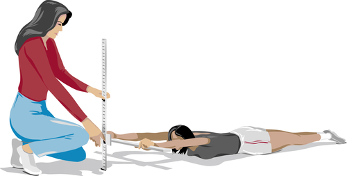
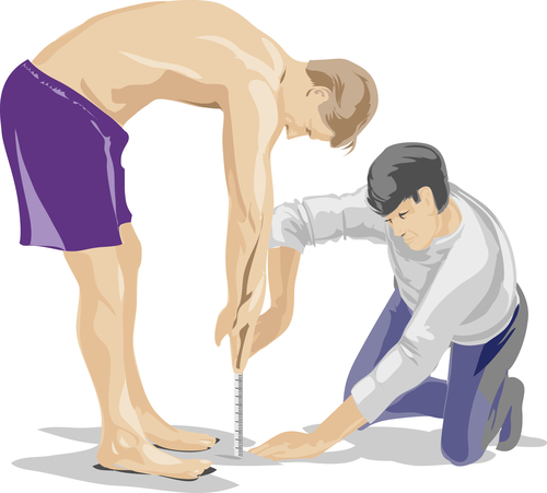
A review of the literature indicates that muscle length is measured primarily through two methods. The first method uses traditional composite tests, which consist of measuring movement across more than one muscle or more than one joint.117 Frequently used composite tests include the sit-and-reach test (Fig. 1-6), Apley’s scratch test (Fig. 1-7), the shoulder-lift test (Fig. 1-8), and the fingertip-to-floor test (Fig. 1-9). The second method is direct measurement of muscle length, in which excursion between adjacent segments of one joint is involved.118
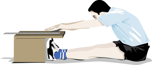

Fig. 1-7 Apley’s scratch test: Composite muscle length test for upper extremity. (From Magee DJ: Orthopedic Physical Assessment, ed 6, Philadelphia, Saunders, 2014.)
Composite Method
Examination of muscle length originated in the physical education literature and can be traced back to the 1940s, when a large number of veterans returned from World War II with limited movement capabilities.119 Following World War II, great emphasis was placed on physical fitness testing, with flexibility being one component that was measured. In 1941 Cureton120 published a “14-Item Motor Fitness Test” that contained four measures of flexibility. These flexibility measurements consisted of composite tests involving flexion and extension of the entire length of the body.
Interest in the importance of examining muscle length was heightened when Kraus121 reported that lack of flexibility and lack of strength were major factors in the high incidence of back pain in the United States. Testing by Kraus,121 who used strength testing and composite flexibility tests, indicated that American children were minimally fit and significantly less fit than European children, leading to the further increase in the use of fitness testing. Fleischman used six fitness tests to perform a factor analytic study that concluded that flexibility was “one of the important parts of overall fitness.”
In the 1970s, the American Alliance for Health, Physical Education, Recreation, and Dance (AAHPERD) built on the work of these fitness pioneers and developed language to describe health-related physical fitness. Health-related physical fitness consists of qualities that “have been formed to contribute to one’s general health by reducing the risk of cardiovascular disease, problems associated with obesity, and chronic back problems.”119 Health-related fitness consists of five categories that should be examined: aerobic endurance, muscular endurance, muscular strength, body composition, and flexibility. The AAHPERD developed a standardized health-related fitness test battery, referred to as the “Physical Best Assessment Program.” Included in this program is the composite flexibility test, referred to as the sit-and-reach test119 (described later in this text in Chapter 8). The American College of Sports Medicine122 recommends a flexibility examination consisting of the “sit-and-reach test or goniometer measurements of isolated joints” as part of a suggested comprehensive health fitness evaluation.
Direct Measurement
Not only is flexibility one of the five specific components of health-related physical fitness defined by the AAHPERD, but research indicates that flexibility is highly specific to each muscle involved. It does not exist as a general characteristic but is specific to the joint and muscle in question.117,118,123 This research has shown that it is possible to have ideal muscle length in one muscle crossing a joint and poor flexibility at another joint in the body. Harris117suggested that “there is no evidence that flexibility exists as a single general characteristic of the human body. Thus no one composite test can give a satisfactory index of the flexibility characteristics of an individual.”
Hubley-Kozey118 suggested that composite tests do not provide accurate measurements of flexibility because these tests assess combinations of movements across several joints and involving several muscles. The author continues by indicating that composite tests are of questionable accuracy owing to difficulty in determining which muscles actually are being examined and to the complexity of the movement. In conclusion, Hubley-Kozey118 suggests that composite tests “serve as gross approximations for flexibility, at best.”
On the basis of information provided by authors such as Harris117 and Hubley-Kozey,118 composite measurement does not appear to be the appropriate measurement technique for muscle length. Therefore in this text, every effort is made to provide only direct measurement of flexibility in describing techniques for upper (see Chapter 6) and lower (see Chapter 14) extremity muscle length testing.
Procedures for Measurement
Instrumentation
Three primary types of instruments will be employed in this text in the measurement of ROM and muscle length. These instruments include the universal goniometer and variations of this measurement tool, the inclinometer and its variations, and linear forms of measurement such as the tape measure. A description of each type of instrument and activities that will help the student become familiar with each instrument are presented in this section.
Universal Goniometer
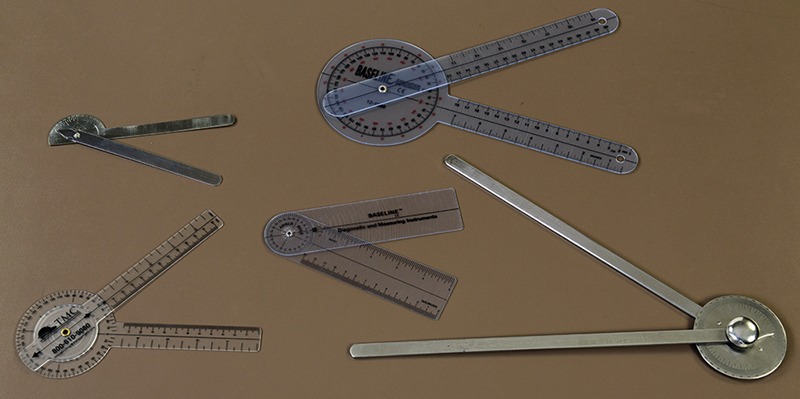
The universal goniometer is produced in a variety of forms and sizes (Fig. 1-10). Most commonly, the universal goniometer is made of either metal or clear plastic and consists of a central protractor portion on which are mounted two arms of varying lengths. The protractor portion of the goniometer may be either a full circle or a half circle, both of which are calibrated in degrees. Although the scales of some goniometers are marked in gradations of 2.5 or 5 degrees, for optimal accuracy the scale should be marked at 1-degree intervals. Many goniometers are marked with a line that runs from the 0-degree to the 180-degree mark on the protractor. This line represents the base line of the protractor and serves as a reference point for measurements. One of the two arms of the goniometer is an extension of the protractor (the stationary arm); the other arm is riveted to, and can move independently of, the protractor (the moving arm) (Fig. 1-11). The central rivet, which attaches the moving arm to the protractor, functions as the axis, or fulcrum, of the goniometer.
If the goniometer is made of metal, the end of the moving arm that is in contact with the protractor (the proximal end) should be tapered to a point on its end or should contain a cutout so that the degree indicators on the protractor scale can be viewed (see Fig. 1-10). This concern is not relevant with a plastic goniometer because the scale can be viewed easily through the plastic arm. The arms of a plastic goniometer generally are calibrated along their length in centimeters or inches for convenience when linear measurements are needed. Additionally, a prominent line extends from the axis of the goniometer down the midline of each arm, providing a landmark on the goniometer that can be maintained in line with bony landmarks on the body during goniometric measurements (see Fig. 1-11).
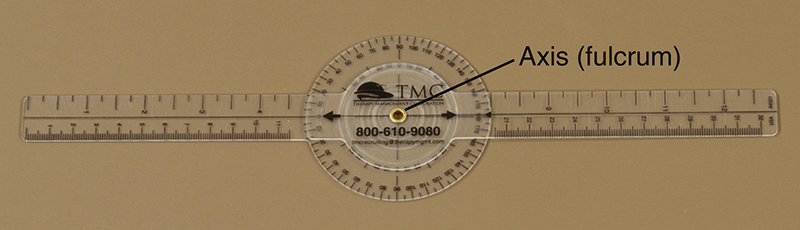
Fig. 1-11 Plastic universal goniometer with full circle protractor. Stationary arm, moving arm, and axis are labeled. Scale of goniometer is marked in increments of 1 degree.
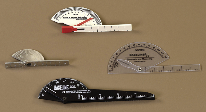
Many modifications of the basic design for the universal goniometer exist. One of the most common, and one that is used in this text, is the finger goniometer. The finger goniometer is basically a scaled-down version of the universal goniometer, with some modifications so that it fits the finger joints more precisely (Fig. 1-12). The finger goniometer is designed to be used over the dorsum of the finger joints, and many styles have broad arms that lie flat against the dorsal surfaces of the metacarpals or phalanges when the goniometer is in place. Some styles of finger goniometer are limited as to the amount of extension that can be measured because of a physical block built into the goniometer at 30 degrees of extension.
Further Exploration: Familiarization with the Universal Goniometer
The activities in Box 1-1 are designed to help the reader become familiar with a goniometer and attain proficiency in manipulating the device and reading the scale correctly. Select a goniometer and locate the parts and features listed in Box 1-1. Make sure several different styles of goniometers are examined and the features of each are compared.
Inclinometer
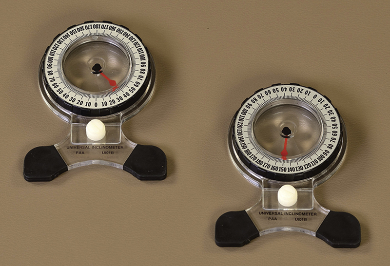
An inclinometer consists of a circular, fluid-filled disc with a bubble or weighted needle that indicates the number of degrees on the scale of a protractor. Most inclinometers are calibrated or referenced to gravity, analogous to the principle related to the level used by a carpenter. Because gravity does not change, using gravity as a reference point means that the starting position of the inclinometer can be identified and repeated consistently.
Inclinometers are available in two types: mechanical and electronic. The least expensive of the two is the mechanical, with most inclinometers today consisting of a protractor and a weighted gravity-pendulum indicator that remains in the vertical position to indicate degrees on the protractor (Fig. 1-13).
A second type of mechanical inclinometer is the fluid-level inclinometer, which indicates degrees by alignment of the meniscus (bubble) of the fluid to the protractor. Although it was used in the past, the fluid-level goniometer is not used frequently today; most clinicians who use inclinometers choose to use the weighted gravity-pendulum device.
Electronic inclinometers are more expensive, may have to be connected to computers with special programs and software, and frequently must be calibrated against some horizontal surface between measurements. Given that the mechanical inclinometer is easy to use, inexpensive, and fairly well represented in research in the literature, this textbook presents only information related to the mechanical inclinometer.
The inclinometer can be held against the patient during a variety of movements, or the device can be mounted on a frame. Examples of mounting the inclinometer onto a plastic frame include the cervical range of motion (CROM) device and the back range of motion (BROM) device (both manufactured by Performance Attainment Associates, Lindstrom, Minn.).

Fig. 1-14 Cervical range of motion (CROM) device; note inclinometers mounted vertically in frontal plane (to measure lateral flexion), vertically in the sagittal plane (to measure flexion and extension), and in the horizontal plane on top of the head (to measure rotation).
CROM
The CROM device consists of a plastic frame that is placed over the patient’s head, aligned on the bridge of the nose and on the ears, and secured to the back of the head with straps made of Velcro (Fig. 1-14). Cervical flexion and extension are measured by an inclinometer mounted on the side of the headpiece. An inclinometer mounted on the front of the headpiece is used to measure lateral flexion. Both inclinometers work by force of gravity. To measure cervical rotation, a compass inclinometer is attached to the top of the headpiece in the transverse plane and operated in conjunction with a magnetic yoke. The yoke consists of two padded bars, mounted on the shoulders, that contain magnetic poles.
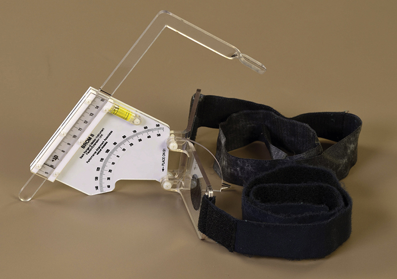
BROM
The BROM device consists of two plastic frames that are secured to the lumbar spine of the patient by two elastic straps. One frame consists of an L-shaped slide arm that is free to move within a notch of the fixed base unit during flexion and extension; ROM is read from a protractor scale (Fig. 1-15). The second frame has two measurement devices attached to it (Fig. 1-16). One attachment is a vertically mounted gravity-dependent inclinometer, which measures lateral flexion. The second attachment is a horizontally mounted compass to measure rotation. During measurement of trunk rotation, the device requires a magnetic yoke to be secured to the pelvis.

Further Exploration: Familiarization with the Inclinometer
The activities in Box 1-2 are designed to help the reader become familiar with an inclinometer and attain proficiency in manipulating the device and reading the scale correctly. Make sure several different styles of inclinometers are examined and the features of each are compared. Compare various free-standing inclinometers versus the inclinometers mounted on the CROM and the BROM.
Tape Measure
One of the simplest tools for measuring ROM and muscle length is the tape measure (or ruler) (Fig. 1-17). Tape measures can be made of cloth or metal. They can possess a centimeter scale, an inch scale, or both. The tape measure is easy to use and is readily available in most clinics. One negative aspect related to use of the tape measure is that most systems used for rating ROM and muscle length impairment rely on measurement in degrees.
Further Exploration: Familiarization with the Tape Measure
The activities in Box 1-3 are designed to help the reader become familiar with a simple tape measure and attain proficiency in manipulating the device and reading the scale correctly. Make sure several different styles of tape measures are examined and that the features of each are compared.

Techniques for Measuring Range of Motion and Muscle Length
Regardless of the instrument that is used, the individual who uses the measurement tool must become skilled in its use. Once a level of comfort in handling and reading a measurement device has been attained, the user must become skillful in using the instrument to measure joint ROM and muscle length. Skill in the use of any measurement device comes only after much repeated practice. Practice in using an instrument should continue until the user has established a high level of intrarater reliability (more detailed information on reliability is presented in Chapter 2), that is, repeated measurements taken by the same person on the same subject should be identical or should fall within a small margin of error. Because techniques of measurement differ from joint to joint, each examiner should practice the techniques until all measurements can be performed in a reliable manner.
Many of the steps involved in measuring joint ROM and muscle length are the same, no matter which joint is being measured. These steps provide the basic framework for measurement and are outlined in Box 1-4 and expounded in this section. How the basic steps are applied at each joint, such as which landmarks are used for alignment of the instrument or what patient positioning is used, differs from joint to joint. The use of standardized techniques is critical for accurate measurement of joint ROM and muscle length. Without standardized techniques, ROM and muscle length measurements are likely to be unreliable and, thus, of questionable validity.5,124,125 Specific techniques for measuring ROM at each joint are provided in Chapters 3 through 5 for the upper extremity, Chapters 8 through 9 for the spine and the temporomandibular joint, and Chapters 11 and 13 for the lower extremity. Specific techniques for measuring muscle length are presented in Chapters 6 and 14.
Preparation for Measurement
Before a patient’s ROM or muscle length is measured, the examiner should determine whether measurement of active or passive ROM is most appropriate. Both active ROM (AROM), which occurs when a patient moves a joint actively through its available ROM, and passive ROM (PROM), which occurs when the examiner moves the patient’s joint through the available ROM, may be used to examine the amount of motion available at a given joint. Although in many cases the examiner will be interested in how much AROM the patient possesses, sometimes PROM may be the motion of interest. For example, a patient with supraspinatus tendinitis may be unwilling to abduct the shoulder more than 75 degrees because of pain, so AROM would be limited to 0 to 75 degrees. To ensure that the patient is not developing adhesive capsulitis of the shoulder, the examiner also may wish to measure the amount of passive shoulder abduction that is present. In some instances, the examiner has no choice but to measure PROM because the patient is unable or unwilling to perform AROM. Such cases include measuring ROM in infants, in young children, and in any patient who lacks the motor control to perform active movement at the joint in question. In its Guides to the Evaluation of Permanent Impairment,41 the AMA recommends the measurement and comparison of both AROM and PROM in the evaluation process.
Active and passive ROM may differ widely for a given joint in an individual, particularly if muscle weakness, pain, or related pathologies are present. Studies that have compared AROM and PROM in subjects without pathology have reported that PROM is greater than AROM for most joints.58,126-129 In many cases, the increase in PROM over AROM is significant. However, PROM is not greater than AROM at all joints. For example, measurements of ankle dorsiflexion ROM tend to be higher when the patient actively dorsiflexes the ankle than when passive motion alone is measured. Because of the variability that exists between AROM and PROM even in pathology-free individuals, care should be taken to document the type of ROM (AROM or PROM) measured in each patient.
Instructing the Patient
Patients should be provided with thorough instructions before any examination technique, including taking ROM and muscle length measurements, is performed. Measurement of ROM and muscle length, particularly active motion, requires the full cooperation of the patient. As the patient’s understanding of the procedure increases, so does the likelihood that the patient will provide his or her best effort during the process.
Before beginning the procedure, describe to the patient exactly what will be taking place and why the measurement must be performed. Show the patient the measurement tool, and explain in laypersons’ terms its purpose and how it will be used. Instruct the patient in the position he or she is to assume, again using laypersons’ terms and avoiding terms such as supine or prone. Detailed explanations of every step of the procedure should not be provided initially because they will only confuse the patient. A brief, general explanation is best at this point, and additional explanations may be given once the procedure is in progress. An example of initial patient instructions is as follows:
“Ms. Haynes, I need to measure how much you can move your knee. This information will tell me how much progress you are making since your surgery and help me estimate how soon you will be able to be discharged from treatment. I am going to use this instrument, called a goniometer, to measure your movement. I will need you to lie on this table on your back so that I can perform the measurement.”
Positioning the Patient: Measuring Joint Range of Motion
Proper positioning of the patient during measurement is critical to accurate measurement. The choice of a preferred patient position for measurement of motion at each joint is based on several criteria. For a position to be considered optimal, all criteria should be met. Although this is not an exhaustive list, the major criteria used in selecting a preferred patient position for measurement of ROM are as follows:
1. The joint should be placed in the zero starting position. The zero starting position for almost all joints is the anatomical position of that joint (described previously). The only joint that is not placed in the anatomical position to start is the forearm, which is placed midway between full pronation and full supination (the neutral position of the forearm). When a joint is positioned in the zero starting position, the joint is considered to be at 0 degrees ROM.
2. The joint should be positioned such that the proximal segment of the joint is stabilized most easily. This positioning allows maximal isolation of the intended motion.
3. The bony landmarks to be used to align the measurement tool should be palpable and in proper alignment. In some cases, this necessitates placing more proximal joints out of anatomical position. For example, when flexion of the wrist is measured, the shoulder is abducted to 90 degrees, the elbow flexed to 90 degrees, and the forearm pronated for placement of the bony landmarks for goniometric alignment in a linear relationship.
4. The joint to be measured should be free to move through its complete available ROM. Motion should not be blocked by external objects, such as the examining table, or by internal forces, such as muscle tightness. An example of the latter is positioning the patient in the prone position to measure knee flexion. Because tension in the rectus femoris muscle can limit knee flexion when the hip is extended (patient positioned prone), a better position for this measurement is with the patient supine. Such a position allows free flexion of the hip during knee flexion, thus eliminating potential restriction of knee flexion by rectus femoris tightness.
5. The patient must be able to assume the position. In some cases, this criterion cannot be met, and an alternative position must be used. In any instance in which an alternative position is used, the examiner should design the position so that it adheres as closely as possible to the previous four criteria.
The amount of ROM measured may vary significantly, depending on the position in which the patient is placed during the measurement. Two studies have demonstrated a statistically significant difference in the ROM obtained from a joint when the position in which the joint was measured was altered. A significantly higher amount of shoulder abduction was obtained when active or passive shoulder abduction was measured with the patient in the supine, compared with the sitting, position.130 Similarly, when hip lateral rotation was measured with the patient in both seated and prone positions, significantly more motion was obtained in the prone position.131 Preferred patient positions are provided for each joint measurement technique described in this text. Whenever a position other than the preferred position is used, careful documentation should be made of the exact position chosen. In this way, techniques used in ROM measurements can be duplicated by others, and more accurate comparisons of measurements taken on separate occasions or by different examiners can be made.
Further Exploration: Preferred Patient Position
The following activities are designed to help the student evaluate and design preferred patient positions for measurement of ROM:
2. Analyze the following scenarios, devising a preferred patient position in each situation. Once your preferred position is complete, apply the criteria listed. How well does your devised position meet the criteria? Make modifications to your devised position as needed, so that it adheres more closely to the criteria.
A. Mr. Barnes suffered a spinal cord injury 2 years previously, currently has a decubitus ulcer on his sacrum, and is unable to sit or lie supine. How would you alter the preferred patient position for Mr. Barnes to perform the following measurements? (Refer to the techniques in Chapters 3 to 5 and Chapter 11 for information on the standard method for performing each measurement.)
i. Shoulder flexion
ii. Wrist extension
iii. Forearm pronation
iv. Hip abduction
v. Hip lateral rotation
B. Mrs. Kelley is 8 months pregnant and is unable to lie on her right side because of pressure placed by the baby on her inferior vena cava. She is also unable to lie prone. How would you alter the preferred patient position for Mrs. Kelley in order to perform the following measurements? (Refer to the techniques in Chapters 3 and 11 for information on the standard method for performing each measurement.)
i. Hip extension (consider both right and left sides)
ii. Shoulder extension (consider both right and left sides)
Positioning the Patient: Measuring Muscle Length
Please note that the preparation for measurement and instructions to the patient are similar, whether one is measuring ROM or is examining muscle length. However, positioning of the patient differs for the two types of measurement. When muscle length is examined, the following guidelines for patient positioning should be followed:
1. The muscle to be measured should be placed in the fully elongated position. In measurement of muscle length, the examiner is most concerned about the final, elongated position of the muscle and is not as concerned about measurement from the zero starting position (as would be appropriate for measurement of joint ROM). In some instances, movement is initiated from the zero position to demonstrate to the patient the motion desired, but in most cases, the muscle is placed in the elongated position and the measurement is taken.
2. As much as possible, the muscle should be isolated across one, or possibly two, joints. Composite tests that measure movement across three or more joints should not be used. (Refer to the earlier section of this chapter on the history of muscle length testing.)
3. The bony landmarks to be used to align the measurement tool should be palpable and in proper alignment. In some cases, this necessitates placing more proximal joints out of anatomical position. For example, when muscle length of the extensor digitorum muscle is measured, the shoulder is abducted to 70 to 90 degrees, the forearm pronated, and the fingers flexed, to place the bony landmarks for goniometric alignment in a linear relationship.
4. Motion should not be blocked by external objects such as the support surface or a pillow.
5. The patient must be able to assume the position. In some cases, this criterion cannot be met, and an alternative position must be used. In any instance in which an alternative position is used, the examiner should design the position so that it adheres as closely as possible to the previous four criteria.
Stabilization
Accurate measurement of joint ROM and muscle length requires stabilization of the proximal bony segment of the joint being measured. Failure to provide adequate stabilization will prevent isolation of the intended motion and may allow the patient to substitute motion at another joint for the motion requested. For example, a patient who lacks forearm pronation may abduct and medially rotate the shoulder in an attempt to substitute for the lack of forearm motion. If the examiner fails to stabilize the humerus in an adducted position during measurement of forearm pronation, the patient may perform the substitute motion, and the measurement of forearm pronation would then be inflated falsely. Three separate studies6,132,133 demonstrated that measurements of shoulder internal rotation with the scapula stabilized yielded significantly different results than when the motion was measured without scapular stabilization.
Lack of sufficient stabilization also may affect the reliability of measurements of ROM or muscle length testing. Ekstrand et al73 performed ROM and muscle length testing of selected lower extremity joints in adult male subjects using a modified goniometer and a Leighton flexometer. Standardized testing procedures were employed, and the motions were repeated on two occasions, 2 months apart. On the first occasion, subjects were positioned on a soft padded surface; on the second occasion, measurements were made with the subject positioned on a hard wooden board. Results demonstrated significantly lower intratester variability for both ROM and muscle length measurements when patients were measured while positioned on a hard surface compared with a soft surface.
The ease with which the proximal joint segment is stabilized varies from joint to joint. In some instances, the patient’s weight assists in stabilizing the proximal joint segment, but the examiner should always stabilize the proximal segment manually as well. In general, smaller segments, such as the forearm, are easier to stabilize than are larger segments, such as the pelvis. Some motions (e.g., shoulder flexion, hip flexion) cannot be isolated completely134 and in those cases, the examiner must realize that the motion measured is, at a minimum, a combination of motion at the joint being measured and motion at the next most proximal articulation.
Directions and illustrations for stabilization are provided for each ROM and muscle length testing technique found in this text. The examiner should be very careful to provide the stabilization indicated when performing each measurement technique. Failure to do so could result in inaccurate and unreliable results.
Estimating Range of Motion and Determining End-Feel
Once the patient has been positioned and the proximal joint segment stabilized, the examiner should move the joint passively through the available ROM. This maneuver accomplishes a variety of objectives. First, by movement through the ROM to be measured, the patient is made aware of the exact movement to be performed and can cooperate more fully and accurately with the procedure. Second, a rough estimation of the patient’s available ROM can be made by the examiner. Estimating the patient’s ROM provides the examiner with a self-check against gross errors in reading the goniometer. For example, if the examiner estimates that the patient has 125 degrees of elbow flexion but reads 55 degrees on the goniometer, then an error in measurement obviously has been made (in this case, the wrong scale on the goniometer has been read). Estimating the patient’s ROM before measurement is performed is a particularly valuable technique for the novice examiner because novices are prone to error in reading the measurement device. Finally, moving the patient passively through the ROM allows the examiner to note any limitations to full ROM, such as those caused by pain, muscle tightness, or other reasons.
Clues to the cause of ROM limitations may be obtained by examining the quality of resistance at the end of ROM. Each joint has a characteristic feel to the resistance encountered at the end of normal ROM. Typical end-feels encountered at the end of normal ROM include bony, capsular, muscular, and soft-tissue end-feels.135,136 These end-feels are described in the activities that follow this section and are defined for each joint in the introductory material for Chapters 3 to 5 and 11 to 13. Chapters 6 and 14 describe measurement of muscle length of the upper and lower extremities, respectively. Given that the muscles are placed in the fully elongated position for these measurements, the end-feel is muscular.
Other end-feels are encountered only in situations of joint pathology. These include empty, muscle spasm, and springy block end-feels. Although explanations of these end-feels are beyond the scope of this text, definitions can be found in any basic musculoskeletal examination text.136,137 Deviation from the expected end-feel when passive ROM is performed at a joint should alert the examiner that further examination of the joint is warranted.
Further Exploration: Identifying End-Feels
Bony End-Feel: Elbow Extension
The bony end-feel occurs when approximation of two bones stops the ROM at a joint. The quality of the resistance felt is very hard and abrupt, and further motion is impossible.
1. Position the subject in the supine or sitting position.
2. Grasp the posterior aspect of the subject’s distal humerus in one hand and the anterior aspect of the distal forearm in the other hand.
3. Flex the subject’s elbow slightly, then gently return it to the fully extended position, repeating this maneuver several times.
4. While performing the passive movement described in step 3, pay close attention to the feel of the resistance at the point of full elbow extension. The resistance should feel hard and abrupt—a bony end-feel.
Capsular End-Feel: Hip Medial Rotation
The capsular end-feel occurs when the joint capsule and the surrounding noncontractile tissues limit the ROM at a joint. The quality of the resistance felt is firm but not hard. There is a very slight “give” to the movement, as would be felt when a piece of leather is stretched.
1. Position the subject in the sitting position.
2. Place one hand on the subject’s knee and the other hand over the subject’s medial malleolus.
3. Passively rotate the subject’s hip medially by moving the subject’s leg laterally (keeping the knee stationary) until firm resistance is felt. From this point, oscillate the subject’s leg medially and laterally very slightly without allowing the knee to move.
4. While performing the passive movement described in step 3, pay close attention to the feel of the resistance at the point of full medial rotation of the hip. The resistance should feel firm and leathery—a capsular end-feel.
Muscular End-Feel: Knee Extension with Hip Flexion
The muscular end-feel occurs when muscular tension limits the ROM at a joint. The quality of the resistance felt is firm, although not as firm as with the capsular end-feel, and somewhat springy.
1. Position the subject in the supine position.
3. Flex the subject’s hip completely. Then slowly extend the subject’s knee until resistance is felt. From this point, gently oscillate the leg into full extension and then into slight flexion.
4. While performing the passive movement described in step 3, pay close attention to the feel of the resistance at the end point of knee extension. The resistance should feel firm and slightly springy—a muscular end-feel.
Soft Tissue End-Feel: Knee Flexion
1. Position the subject in the supine position.
2. Place one hand on the anterior aspect of the subject’s knee, and grasp the subject’s ankle with the other hand.
3. Flex the subject’s knee completely (slight hip flexion is allowed during this procedure, but only enough to allow full flexion of the knee) until the subject’s calf is stopped by his or her posterior thigh. From this point, oscillate the leg into, and slightly out of, full knee flexion.
4. While performing the passive movement described in step 3, pay close attention to the feel of the resistance at the end point of knee flexion. The resistance, which is caused by compression of the soft tissue of the calf and posterior thigh, should feel mushy or soft—a soft-tissue end- feel.
Palpating Bony Landmarks and Aligning the Measurement Device
Accurate palpation of landmarks and precise alignment of the measurement device with those landmarks are critical to correct measurement of joint ROM and muscle length. Bony landmarks are used for alignment of the measurement device whenever possible because bony structures are more stable and are less subject to change in position caused by factors such as edema or muscle atrophy.
Aligning the Goniometer
Three landmarks, as a minimum, are used to align the goniometer. Two landmarks are used to align the arms of the goniometer—one landmark for the stationary arm and one for the moving arm. The stationary arm is generally aligned with the midline of the stationary segment of the joint, while the moving arm is aligned with the midline of the moving segment of the joint. The bony landmarks provided for alignment of the goniometer arms are generally target points on the bones of the stationary and moving joint segments. Although the arms of the goniometer may not actually cross these bony targets once the instrument is aligned, the examiner should sight the midline of each goniometer arm so that it points directly at the corresponding bony target.
The third bony landmark provides a point for alignment of the fulcrum of the goniometer. The fulcrum of the goniometer is placed over a point that is near the axis of rotation of the joint. However, because the axis of rotation for most joints is not stationary but moves during motion of the joint, the goniometer’s fulcrum often will not remain aligned over its corresponding bony landmark throughout the ROM. Because the joint axis is not stationary, the landmark for alignment of the fulcrum of the goniometer is the least important of the three landmarks for goniometer alignment. To ensure accurate alignment, priority should be given to alignment of the stationary and moving arms of the goniometer. Once the examiner is satisfied that the goniometer is aligned correctly, a reading should be taken from the scale of the goniometer at the beginning of the ROM (see “Determining and Recording the Range of Motion with the Goniometer,” discussed subsequently).
Aligning the Inclinometer
Only one bony landmark per measurement is needed for alignment of the standard inclinometer; therefore, the measurement device is not subject to error in estimating multiple anatomical landmarks for one measurement. An inclinometer with a two-point contact base is preferred because this type of base best maintains contact over convex surfaces of the body. Because of its ease of use, the inclinometer has gained favor for measurement of the spine.
The inclinometer has not been used as frequently as the goniometer to measure the extremities because of difficulties involved in stabilizing the instrument along the different anatomical contours of the body, especially on smaller joints. Additionally, any attempt to strap the inclinometer to the extremity introduces problems of soft-tissue variability, edema, and slippage.
Aligning the Tape Measure
With the tape measure, specific landmarks are established before measurement. These landmarks may be only anatomical, such as the distance between the tip of the chin and the sternal notch. Sometimes an anatomical landmark may be combined with the support surface on which the subject is sitting or lying, such as the perpendicular distance between the tip of the olecranon fossa and the support surface in a subject lying supine with hands clasped behind the head.
Determining and Recording the Range of Motion with the Goniometer
Determination of the patient’s ROM is accomplished by comparing the reading taken from the goniometer with the patient in the starting position versus a second reading that is taken once the patient has completed the AROM or PROM. Before this second reading is taken, the goniometer alignment must be rechecked. Bony landmarks must be palpated again at the end of the patient’s ROM, and the arms and the fulcrum of the goniometer readjusted as necessary, so that alignment is once again accurate. Failure to confirm accurate goniometer alignment before the instrument is read may result in gross errors in ROM measurement.
When the scale of the goniometer is read, the reading is taken at the point where the midline of the end of the moving arm crosses the scale of the protractor portion of the instrument. Many goniometers are imprinted with more than one scale, and these scales may encircle the protractor portion of the instrument in opposing directions. The examiner must pay careful attention to make sure that the correct scale is being read (see points 4, 5, 6, and 7 under “Moving Arm” in Box 1-1).
After readings have been taken from the goniometer at the beginning and at the end of the patient’s movement, the examiner is ready to document the ROM. Several items must be noted in the record of the patient’s ROM. These items include the following:
• Patient’s name and identifying information
• Date measurement was taken
• Identification of person taking measurement
• Type of motion measured (AROM or PROM)
• Any alteration in patient’s position (from preferred patient position) during measurement
• Beginning and ending readings from the goniometer for each motion measured
This information provides sufficient details should any question arise regarding the patient’s ROM at a particular joint. Additionally, information regarding the type of motion measured and any alterations in normal procedure allow other examiners to reproduce the technique should someone other than the original examiner need to measure the patient’s ROM.
When readings taken from the goniometer are recorded, both the beginning and ending readings should be reported, even if the beginning reading is 0 degrees. The beginning reading tells anyone who needs information from the patient’s record where the ROM begins. Two patients may both have 110 degrees of elbow flexion, but the motion in Patient A may start at 0 degrees and progress to 110 degrees of flexion, whereas the motion in Patient B may start at 25 degrees of flexion and progress to 135 degrees. Recording either patient’s motion as 110 degrees would not allow anyone examining either patient’s record to know where the motion began and where it ended. To avoid confusion on the part of those reading the patient’s record, the use of a single number to record the ROM should be avoided (except in certain cases—see “Single Motion Recording Technique,” discussed later).
Occasionally, the goniometer will not read 0 degrees at the beginning of the ROM, even when the patient is at the 0-degree starting position for that motion. An example of this phenomenon occurs during the measurement of hip abduction and adduction. At the beginning of these two motions, the alignment of the goniometer is such that the stationary and moving arms of the instrument make a 90-degree angle with each other. Thus at the 0-degree starting position for hip abduction and adduction, the scale of the goniometer reads 90 degrees. This reading is taken as equivalent to 0 degrees, and the reading from the goniometer at the end of the ROM is added to or subtracted from 90 degrees to obtain the ROM. For example, in a patient with 20 degrees of hip adduction, the goniometer would read 90 degrees at the beginning of the ROM and 110 degrees at the end of the ROM. Subtract: 110 - 90 = 20. Therefore the patient’s hip adduction ROM is recorded as 0 to 20 degrees hip adduction.
Several methods of recording ROM are available. Two methods are presented here, and the reader may choose which method to use. However, in a clinical situation in which multiple individuals are measuring and recording ROM, a standardized method of recording these measurements should be agreed on by all individuals involved. Otherwise, a great deal of confusion is likely to result among those using the patient record as the basis for decision making.
Single Motion Recording Technique
One method of recording joint ROM involves separately documenting the range of each motion at each joint. Thus when ROM at the shoulder is recorded, shoulder flexion is documented separately from shoulder extension, and shoulder lateral rotation is documented separately from shoulder medial rotation. Both beginning and ending readings from the goniometer are recorded for each motion measured. An example of single motion recording of ROM is provided in Fig. 1-18.
Mrs. Stephenson is able to actively move her right shoulder from the 0-degree starting position to 165 degrees in the direction of shoulder flexion and to 35 degrees in the direction of shoulder extension. Her ROM would be documented as in Fig. 1-18.
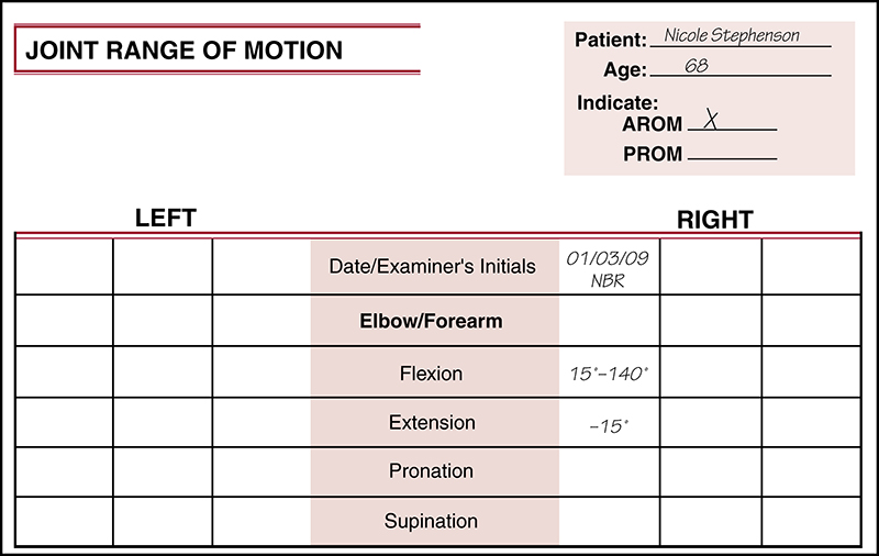
For some motions, the patient may not be able to attain the 0-degree starting position for the movement. In such cases, the patient is limited in one motion and completely lacks the opposing motion. For example, suppose Mrs. Stephenson is unable to attain the 0-degree starting position for elbow extension but instead lacks 15 degrees of full extension (in other words, her elbow is in 15-degree flexion as she begins the flexion movement). Suppose further that she is able to move from this starting position to 140 degrees of elbow flexion. Mrs. Stephenson’s elbow flexion is documented as shown in the chart in Fig. 1-19, since she began the motion at 15 degrees and ended it at 140 degrees. In the case of elbow extension, Mrs. Stephenson has no range of motion because she is unable to attain the 0-degree starting position for the movement. Therefore elbow extension for Mrs. Stephenson is documented as -15 degrees, as shown in Fig. 1-19, indicating that she lacks 15 degrees of attaining the 0-degree starting position for elbow extension. Only in cases in which the patient has no motion in a given direction is a single number used to document ROM.

Now suppose that Mrs. Stephenson’s knee ROM is measured, and the examiner discovers that Mrs. Stephenson is able to attain the 0-degree starting position for knee extension. She also can actively move her knee 10 degrees in the direction of extension and 145 degrees in the direction of flexion. In this case Mrs. Stephenson’s knee extension is recorded as 0 to 10 degrees knee hyperextension. When the normal amount of extension at a joint is 0 degrees, motion into extension beyond 0 degrees is documented as hyperextension. Use of the term hyperextension reflects that the motion is in excess of the normal amount of extension expected at that joint. In this case knee flexion is documented as 0 to 145 degrees flexion, since the starting position for flexion is 0 degrees. Even though Mrs. Stephenson is able to attain more than 0 degrees of extension, the extra motion is not included in the documentation for knee flexion because the flexion movement begins at 0 (Fig. 1-20).


Further Exploration: Documenting Range of Motion using Single Motion Recording Technique
Using the charts that follow, practice documenting ROM by recording the motion for each of the patients presented below:
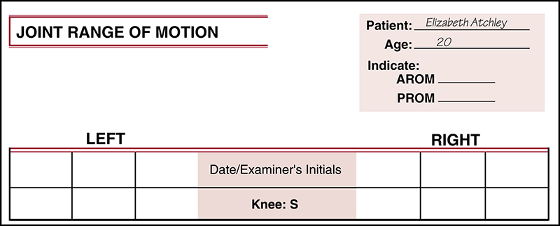
1. Ms. Atchley is able to begin from the 0-degree starting position and to actively move her knee 8 degrees in the direction of extension and 140 degrees in the direction of flexion. Record Ms. Atchley’s knee flexion and extension ROM (Fig. 1-21).
2. Mr. Taman is unable to attain the 0-degree starting position for hip flexion and extension. He begins the motion of hip flexion with his hip at 12 degrees of flexion and is able to actively move from there to 118 degrees of flexion. He is unable to move past 12 degrees of flexion toward the direction of extension. Record Mr. Taman’s hip flexion and extension ROM (Fig. 1-22).
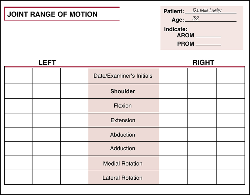
3. Ms. Lusby is unable to abduct her shoulder to 90 degrees. Therefore the examiner measures Ms. Lusby’s shoulder rotation with her shoulder positioned in 45 degrees of abduction. From this position, she is able to attain the 0-degree starting position for shoulder rotation and to actively move her shoulder 60 degrees in the direction of medial rotation and 48 degrees in the direction of lateral rotation. Record Ms. Lusby’s shoulder rotation ROM. What notation should be made of Ms. Lusby’s altered position for testing (Fig. 1-23)?
A wide variety of forms may be used in recording ROM. Appendix B provides a sampling of forms that can be used in the clinical setting.
Sagittal Frontal Transverse Rotational (SFTR) Recording Technique
A second method of recording joint ROM records all motions that occur together in a given plane. For example, all motions occurring at the shoulder in the sagittal plane are recorded on the same line in the patient’s record. Motions occurring in the frontal plane are then recorded, followed by motions occurring in the transverse plane, and so forth. When motion for each plane of movement is recorded, a sequence of three numbers is used. The first number represents the extreme of motion in one direction, the second number represents the starting position, and the third number represents the extreme of motion in the opposite direction. For each plane of motion, movements are listed in the following order:

| Sagittal plane: | Extension/Starting position/Flexion |
| Dorsiflexion/Starting position/Plantarflexion | |
| Frontal plane: | Abduction/Starting position/Adduction |
| Lateral flexion to left/Starting position/ Lateral flexion to right | |
| Transverse plane: | Horizontal abduction/Starting position/Horizontal adduction |
| Rotation: | Lateral rotation/Starting position/Medial rotation |
| Supination/Starting position/Pronation | |
| Eversion/Starting position/Inversion | |
| Rotation to left/Starting position/ Rotation to right |
To use the example of Mrs. Stephenson that was provided previously, under the SFTR system, Mrs. Stephenson’s ROM would be documented thus:
• Shoulder S: 35°-0°-165°
• Elbow S: 0°-15°-140°
• Knee S: 10°-0°-145°
The notation for elbow motion indicates that Mrs. Stephenson is unable to move the elbow into extension, and that she begins flexion at 15 degrees of flexion rather than at the 0-degree starting position. In other words, she has a 15-degree elbow flexion contracture. The chart in Fig. 1-24 shows how Mrs. Stephenson’s elbow ROM is documented by the SFTR method.
On some occasions, motion at a joint is measured with the joint in some position other than the anatomical 0-degree starting position. In these cases, the SFTR system allows easy notation of the altered position. For example, if hip rotation is measured with the hip positioned in 90 degrees of flexion, a notation of the hip’s position can made in the hip rotation record as follows: Hip R (S90): 32°-0°-28°. The designation (S90) indicates that the hip was positioned at 90 degrees in the sagittal plane when the hip rotation measurement was taken.
Further Exploration: Documenting Range of Motion Using SFTR Recording Technique
Using the information already provided for sample patients, Ms. Atchley, Mr. Taman, and Ms. Lusby, document the ROM of each patient using the SFTR technique in the charts provided in Figs. 1-25, 1-26, and 1-27.
Determining and Recording Muscle Length
As indicated previously, in measuring muscle length, the examiner is most concerned about the final, elongated position of the muscle and is not as concerned about measurement from the zero starting position (as would be appropriate for measurement of joint ROM). Therefore for measurement of muscle length, the muscle to be examined is placed in the elongated position, and the measurement is taken using the suggested instrument (as is described in detail in Chapters 6 and 14). This actual measurement is the only information that is documented.
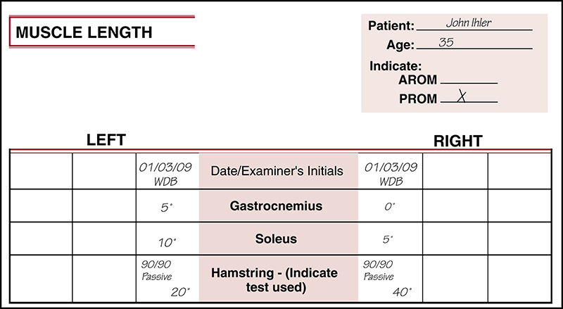
Assume that Mr. Ihler is a 35-year-old weekend tennis player with a diagnosis of patellar tendinitis in the right knee. Measurement of muscles on his right side indicates 0 degrees for the gastrocnemius, 5 degrees for the soleus, and 40 degrees from full knee extension for the hamstrings (using the passive 90/90 test described later in Chapter 14). Measurement of flexibility on his left side indicates 5 degrees for the gastrocnemius, 10 degrees for the soleus, and 20 degrees from full knee extension for the hamstrings. His muscle length data are documented as in Fig. 1-28.
A wide variety of forms can be used for recording muscle length data. Appendix A provides a sampling of forms that can be used in the clinical setting.