Introduction to radiographic equipment
Learning objectives
At the conclusion of this chapter, you will be able to:
• Use correct terminology when discussing x-ray equipment and its parts
• Demonstrate the radiation field and define the central ray
• Explain the differences between primary radiation, scatter radiation, and remnant radiation
• List two effects of scatter radiation
• List the components of the image receptor system
• List the essential features of a typical x-ray room
• Explain the purposes of the control booth and the transformer cabinet
• Safely change the positions of the radiographic table and the x-ray tube
• Demonstrate a detent and explain its function
• Explain the purpose of a collimator
• Describe precautions to be taken to ensure personnel safety from radiation exposure
Key terms
adverse incident
attenuation
Bucky
cassette
central ray
collimator
computed radiography (CR)
control booth
control console
CR reader
detent
grid
image receptor (IR)
latent image
phosphor imaging plate
plate
primary radiation
radiation field
remnant radiation
scatter radiation
scatter radiation fog
tissue density
Trendelenburg position
tube housing
tube port
upright cassette holder
visible image
x-ray beam
x-ray tube
This chapter introduces the useful x-ray beam, discusses the equipment found in a typical x-ray room, and provides some fundamentals of radiation safety. Many of these topics are covered in greater detail later in the text, but it will be helpful for you at this point to have an orientation to the equipment and safety considerations that are central to your work as a limited x-ray operator.
Primary X-ray beam
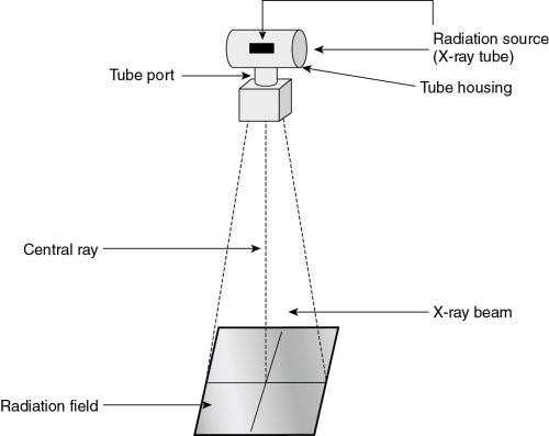
The source of x-rays is the x-ray tube. The internal structure and function of the tube are discussed in Chapter 5. X-rays are formed within a very small area inside the tube. From this point, the x-rays diverge into space. The x-ray tube is surrounded by a lead-lined tube housing. Some of the scattered x-rays are absorbed by the tube housing. X-rays that are created, exit the housing through an opening called the tube port. These x-rays form the triangular-shaped x-ray beam (Fig. 2-1). The radiation that leaves the tube is called primary radiation. The squared area of the x-ray beam that strikes the patient and x-ray table is called the radiation field. An imaginary line in the center of the x-ray beam and perpendicular to the long axis of the x-ray tube is called the central ray. The central ray is important in positioning the patient because this point is used to align the x-ray tube to the body part to be imaged.
During a radiographic exposure, x-rays from the tube are directed through the patient to the image receptor (IR) (Fig. 2-2). As the x-rays pass through the patient, some of them are absorbed by the patient and others are not. Anatomic structures that have greater tissue density (mass), such as bone, will absorb more radiation than less dense tissue, such as muscle. This results in a pattern of varying intensity in the x-ray beam that exits on the opposite side of the patient. This radiation, called remnant radiation or exit radiation, then passes through to the IR. The IR now contains an “unseen” image called a latent image. This image remains stored in the IR phosphors until it is processed. Processing will convert the latent image into a visible image.

Scatter radiation
When the primary x-ray beam strikes matter, such as the patient or the IR, a portion of its energy is absorbed within the matter. Absorption of the x-ray beam is called attenuation. Attenuated x-rays can be totally absorbed within the body, reduced in energy, or scattered outside of the body. The patient is the primary source of scatter. This scatter radiation generally has less energy than the primary x-ray beam, but it is not as easily controlled. It travels out from the absorbing matter in all directions, causing unwanted exposure to the IR and to anyone who is in the room. This is an important reason why the study of radiation safety is so essential to the limited operator. Radiation safety is discussed briefly at the end of this chapter and more extensively in Chapter 11. The unwanted image exposure caused by scatter radiation is called scatter radiation fog. The production of scatter radiation and the control of the fog it produces are addressed in Chapter 9.
See Box 2-1 for a summary of primary, remnant, and scatter radiation.
 Box 2-1
Synopsis of Primary, Remnant, and Scatter Radiation
Primary radiation
• Definition: the x-ray beam that leaves the tube and is unattenuated, except by air.
• Its direction and location are predictable and controllable.
Remnant (exit) radiation
• Definition: what remains of the primary beam after it has been attenuated by matter (the patient).
• Tissues of different density, or atomic number, in the body absorb x-rays differently and therefore emit x-rays differently. The remnant beam contains a varied pattern of x-ray energies that reflects the different absorption rates.
• The pattern of the remnant radiation creates the x-ray image.
Scatter radiation
Image receptor system
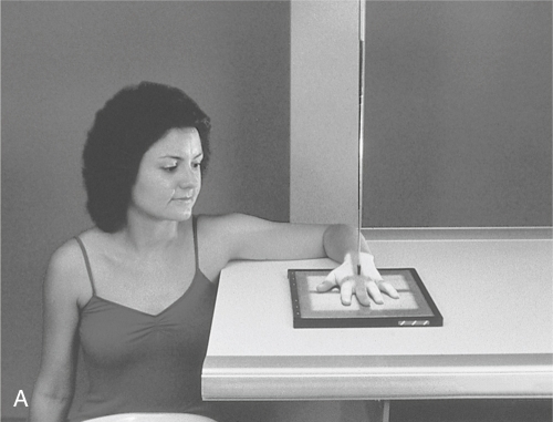
The IR system consists of a cassette that contains a phosphor imaging plate. In the radiology department today, the IR is part of the digital imaging system. One component is a cassette (Fig. 2-3, A). The cassette contains a plate with special phosphors that store the x-ray image until it is processed. The cassette protects the plate’s phosphors from damage and dirt. IR plates come in standard sizes. The most common sizes are listed in Table 2-1. They are manufactured in both English and metric sizes, with most sizes stated in English. In the radiology department, the terms cassette and plate are often used to mean IR.
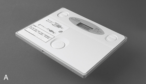
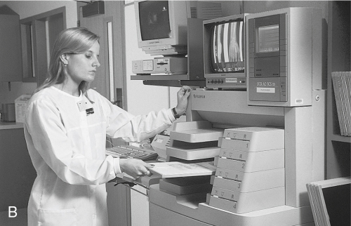
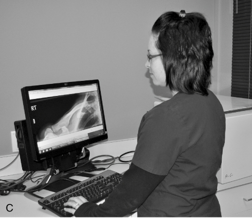
Table 2-1
| Inches | Centimeters |
| 8 × 10 | 18 × 24 |
| 10 × 12 | 24 × 30 |
| 14 × 14 | 35 × 35 |
| 14 × 17 | 35 × 43 |
| 14 × 36 | 35 × 91 |
Most departments in which limited operators work use the computed radiography (CR), a digital imaging system. The x-ray image is produced in digital format using computer technology (see Chapter 8). When CR systems are used, the conventional radiography machine, positioning of the patient, and setting of technical parameters remain the same. However, the image is obtained from a phosphor material inside the CR plate. After the exposure is made, the CR cassette is inserted into a CR reader (Fig. 2-3, B) where the phosphor on the plate is scanned by a laser beam and the final image appears on a computer monitor. The image can then be adjusted for final density and contrast and stored in an electronic file or printed out on laser film (Fig. 2-3, C). The image is read directly from the monitor by the radiologist.
Throughout this text, IR is used to refer to the device that receives the remnant x-ray beam and stores the image of the body part until it is processed.
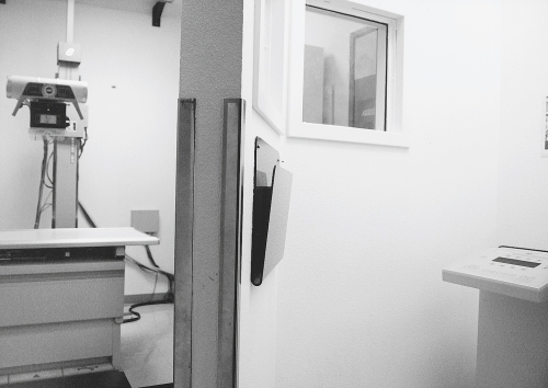
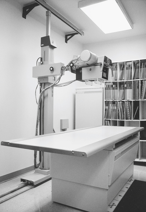
X-ray room
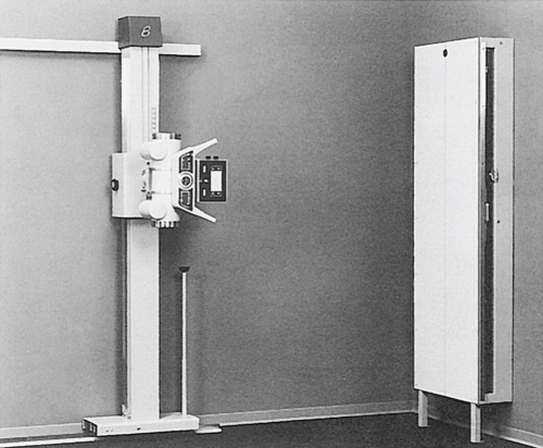
The x-ray room (Fig. 2-4) includes the x-ray equipment itself, a counter area, and a protective control booth. The x-ray machine consists of the x-ray tube, the tube support, the control console (located in the control booth), and the transformer cabinet. There is usually also a radiographic table and a wall-mounted cassette holder for upright studies. In chiropractic offices, there may not be an x-ray table because chiropractic radiography is often done with the patient upright to provide weight-bearing information (Fig. 2-5).
Radiography involves positioning the patient, the IR, and the x-ray tube, and setting the control panel and making the exposure. Before you learn the specifics of radiographic positioning, it is important to understand how the equipment works so that you can position it safely and efficiently.
X-ray equipment may vary considerably, depending on age, manufacturer, and the complexity of procedures for which it was designed. The equipment descriptions provided here highlight the important features of most general-purpose x-ray machines and some of the common variations. If you are currently associated with a clinical facility that has x-ray equipment, it will be helpful to consider the information that follows in relation to the equipment you will be using. When you have learned to use several different x-ray machines, it will be relatively easy to orient yourself to new equipment.
Positioning of the X-ray tube
As stated earlier, the x-ray tube is encased in a barrel-shaped tube housing (Fig. 2-6). This housing is lead-lined for radiation control. The housing protects and insulates the tube and provides a mounting for attachments, which the limited operator uses to position the x-ray tube and to control the size of the radiation field.
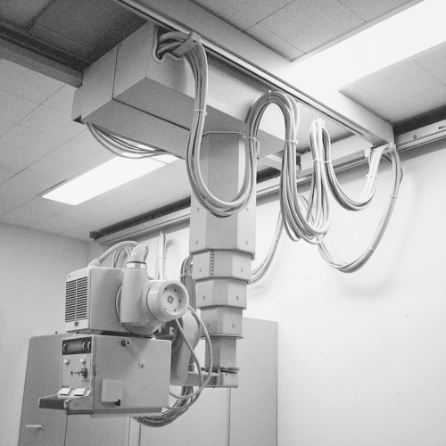
The tube housing may be attached to a ceiling mount or to a tube stand. Both types of mountings provide support and mobility for the tube. These tube supports allow the operator to move the tube, to align it to the patient and the IR, and to adjust its height. A ceiling-mounted tube support (Fig. 2-7), sometimes called a ceiling crane or tube hanger, suspends the x-ray tube from a system of tracks, allowing it to be moved to locations throughout the room. A tube stand (Fig. 2-8) is a vertical support with a horizontal arm that suspends the tube over the radiographic table. The tube stand rolls along a track that is secured to the floor (and sometimes also to the ceiling or wall), parallel to the x-ray table. This enables the tube to move longitudinally along the length of the table.
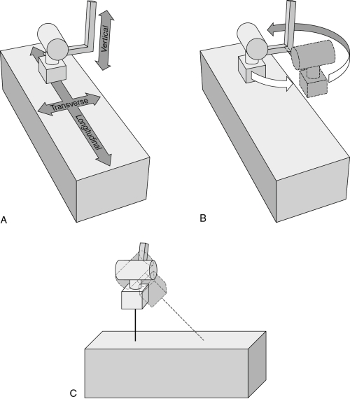
Typical tube motions (Fig. 2-9) include the following:
• Longitudinal—along the long axis of the table
• Transverse—across the table, at right angles to longitudinal
• Vertical—up and down, increasing or decreasing the distance between the tube and the table
• Rotational—allows the entire tube stand to turn on its axis, changing the angle at which the tube arm is extended
• Angular (tilt, roll)—permits angulation of the tube along the longitudinal axis of the table and allows the tube to be aimed at the wall, rather than at the table
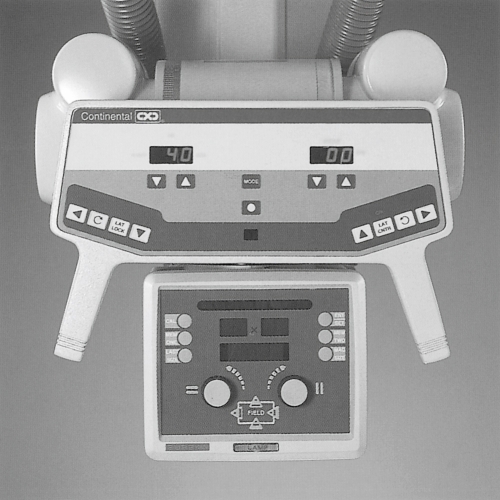
A system of electric and/or mechanical locks holds the tube in position. The control system for all, or most, of these locks is usually an attachment on the front of the tube housing (see Fig. 2-6). To move the tube in any direction, a locking device must be released. It is sometimes possible to force tube movement without first releasing the lock, but this practice will damage the lock, making it impossible to secure the tube in position. Do not attempt to move the tube without first releasing the appropriate lock.
The tube stand and/or the movable portion of the upright cassette holder may move unexpectedly when the electric supply to electric locks is turned off. To avoid damaging the equipment, you must be certain that these units are safely positioned before turning off the power to the locks. One way to accomplish this is to position the x-ray tube immediately above a pillow on the tabletop before shutting down the power supply to the tube support locks.
A detent is a special mechanism that tends to stop a moving part in a specific location. Detents are built into tube supports to provide ease in attaining placement at standard locations. For example, a vertical detent may indicate when the distance from tube to film is 40 inches, a common standard distance. Other detents provide “stops” when the transverse tube position is centered in relation to the table and when the tube tilt position is such that the central ray is perpendicular to the table or to the wall.
Collimator
The collimator is a boxlike device attached under the tube housing (see Fig. 2-6). It allows the limited operator to vary the size of the radiation field. The collimator includes a light that indicates the beam size and location and the center of the field. There is usually a centering light that aids in aligning the central ray to the Bucky tray (Fig. 2-10). Controls on the front of the collimator allow adjustment of the size of each dimension of the radiation field. These dimensions are indicated on a scale on the front of the collimator. A timer controls the collimator light, turning it off after a certain length of time, usually 30 seconds. This helps to avoid accidental overheating of the unit by prolonged use of its high-intensity light.

Radiographic table
The radiographic table is a special unit that is more than just a support for the patient. Although the table is usually secured to the floor, it may be capable of three types of motion: vertical, tilt, and “floating tabletop.”
For vertical table motion, a hydraulic motor, activated by a hand, foot, or knee switch, raises or lowers the height of the table. The table may be lowered so that the patient can sit on it easily and then elevated to a comfortable working height for the limited operator. There will be a detent that stops the table in the standard position for routine radiography. This standard table height corresponds to indicated distances from the x-ray tube. It is important that standard tube-to-film distances be used, so it is necessary to return the table to the detent position after lowering it for patient access. Not all tables are capable of vertical motion.
A tilting table (Fig. 2-11) also uses a hydraulic motor to change position. In this case, the table turns on a central axis to attain a vertical position. This allows the patient to be placed in a horizontal position, in a vertical position, or at any angle in between. The table may also tilt in the opposite direction, allowing the head end to be lowered at least 15 degrees into the Trendelenburg position (Fig. 2-12). A detent stops the table in the horizontal (level) position.

Special attachments for the tilting table include footboards and shoulder guards for patient safety when the table is tilted (Fig. 2-13). You should pay particular attention to the locking mechanisms on these attachments so that you will be able to apply them correctly when needed. Always test the footboard and shoulder guards to be certain that they are securely attached before tilting the table with a patient on it.


The motor that tilts the table is quite powerful and can overcome the resistance of obstacles placed in the way. Step stools and other movable equipment have been crushed because they were under the end of the table and out of view when the table motor was activated. Such a collision can also damage the table. Be certain that the spaces under the table are clear before tilting the table.
The majority of adverse incidents that occur in the radiology department will happen at the x-ray table and upright Bucky (described next). The most frequent adverse incident is a patient falling. Never leave a patient alone on the x-ray table. When making the exposure from behind the control console, always have the patient in eyesight. Box 2-2 lists important safety precautions when moving x-ray equipment.
Box 2-2
Safety Precautions When Moving X-ray Equipment
• Be sure that footboard and shoulder guard are secure before tilting a table with a patient on it.
• Check that no equipment is under the table before tilting it.
• Release locks before attempting to move the x-ray tube.
• Move the x-ray tube out of the way before assisting a patient to or from the table to avoid injuring the patient.
• Be sure that equipment is in a safe position before shutting off power to the locks.
• Ensure that the patient cannot or will not fall off the table.
A floating tabletop allows the top of the table to move independently of the remainder of the table, which makes it easy to align the patient to the x-ray beam. This is a common feature of modern tables. This motion may involve a mechanical release that allows the tabletop to be shifted manually, or the movement may be power-driven, activated by a small control pad with directional switches.
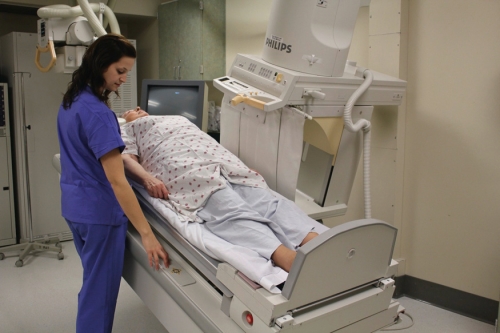
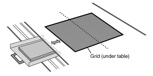
Mounted under the tabletop surface is a grid device that absorbs most of the scatter radiation coming off the patient and tabletop and prevents it from reaching the IR. Most of these devices include a small motor that moves the grid during the exposure. The device also includes a pull-out tray to hold the IR plate and center it to the central ray. The grid and tray device is called a Bucky (Fig. 2-14), named after its inventor, American radiologist Gustav Bucky. Some tables may have a stationary grid that does not move during the exposure. The entire Bucky unit can be moved along the length of the table and locked into position where desired. The Bucky and grid are generally used only for radiography of body parts that measure 10 to 12 cm or more in thickness (about the size of the average adult neck or knee) or when the kilovoltage (kVp) is greater than 60. When the grid is not needed, the IR is placed on the tabletop or in an upright cassette holder that does not incorporate a grid. Fig. 2-15 shows a patient having an x-ray taken on the tabletop without the Bucky and a patient having an x-ray that utilizes the Bucky. Grids are discussed in Chapter 9.

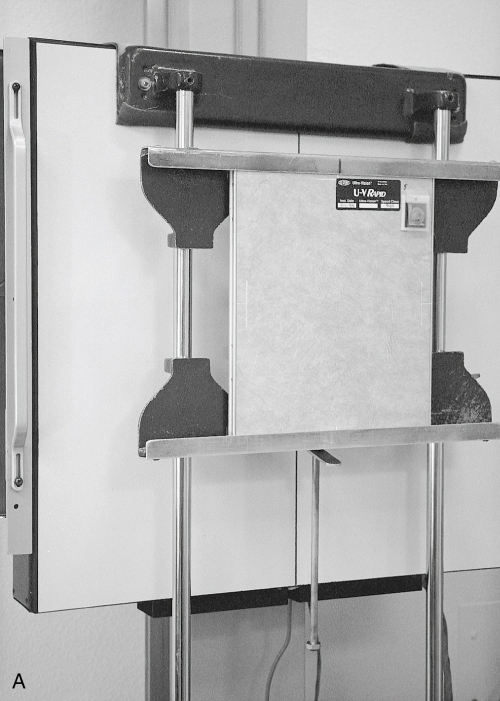
Upright cassette holder
The upright cassette holder, as its name implies, is a device that holds the IR in the upright position for radiography (Fig. 2-16). All x-ray rooms contain an upright holder because many x-rays are done with the patient standing or sitting upright. The holder is usually mounted on a wall and is adjustable in height. It will usually incorporate a Bucky. This unit is typically referred to as the upright Bucky. When the patient is to be sitting or standing at the upright cassette holder for radiography, the tube is angled to face the wall and cassette holder. The distance may be adjusted to 40 inches or to 72 inches, depending on the requirements of the procedure (Fig. 2-17). Similarly to the x-ray table, patient falls can occur at the upright Bucky. Ensure that the patient is able to stand and remain standing for the x-ray exposure, or seat the patient. Often someone may have to hold the patient.


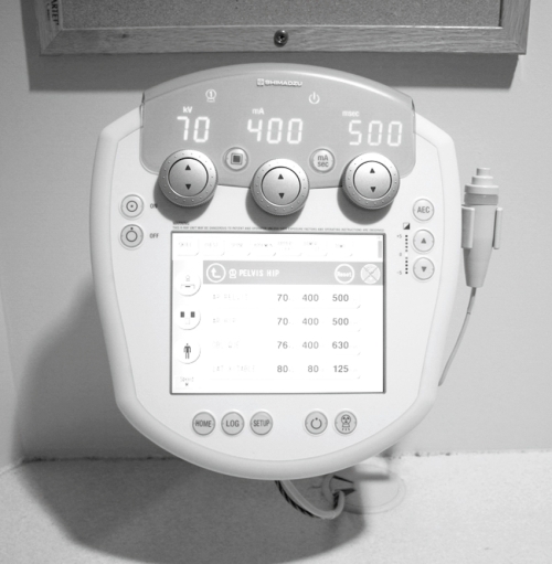
Control console
The control console is located in the control booth. This area is separated from the x-ray room by a lead barrier to protect the limited operator from scatter radiation during exposures. There is usually a lead glass window so that the limited operator can observe the patient from the control booth. The control console, or “control panel,” is the access point at which the limited operator sets the exposure factors and initiates the exposure (Fig. 2-18). A typical radiographic control console has buttons or switches for controlling the exposure and dials or digital readouts that indicate the settings. Details of the control panel are discussed in Chapter 6.
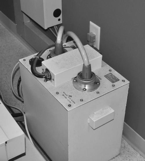
Transformer cabinet
The transformer is an essential part of the x-ray machine. Its function is to produce the high voltage required for x-ray production as well as the low milliamperage (mA) needed in the x-ray tube. These are discussed in Chapter 5. The limited operator’s work does not involve contact with the transformer. It is a large square unit standing in a corner of the x-ray room, connected by cables to both the control console and the x-ray tube (Fig. 2-19).
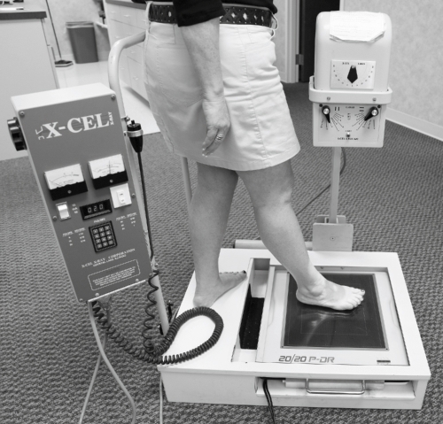
Podiatric radiology
Podiatric radiology is defined as radiography of the ankle and foot. Podiatrists typically have their own private offices and need to have x-ray equipment available to image the foot and ankle. Podiatric x-ray machines have all the components of conventional x-ray machines but are specially designed for imaging these parts of the body (Fig. 2-20). The kVp on a podiatric machine is typically the same as on a conventional machine; however, the mA is considerably lower.
Fundamental radiation safety
Radiation exposure may pose a health hazard to radiographers if proper safety precautions are not observed. This subject is treated in greater depth in Chapter 11. The potential hazard is greater for the limited operator than for the patient because the limited operator is in frequent daily contact with the possibility of exposure. At this point, you need to feel confident that you are not endangering yourself or others as you become acquainted with the radiography department.
As stated earlier in this chapter, scatter radiation is present throughout the x-ray room during an exposure. Be aware that x-rays travel at the speed of light, do not linger in the room after the exposure, and are not capable of making the objects in the room radioactive. The only time that a radiation hazard exists is during the x-ray exposure itself.
The sources of radiation are the x-ray tube and any matter that is in the path of the primary x-ray beam. The principal source of scatter radiation is the patient. When a safety barrier such as a lead wall is placed between the sources of radiation and the limited operator, the limited operator is safe from exposure. X-rays travel in straight lines and do not turn corners. Scatter radiation is not powerful enough to generate additional radiation of concern when it interacts with matter, so it is not necessary for the control booth to be sealed.
Limited operators should always be completely behind the lead barrier of the control booth during exposures. They should not be involved in holding patients who are unable to cooperate during the exposure. Immobilization devices should be used or, if necessary, assistance should be obtained from the patient’s family. Before making an exposure, the limited operator should perform a safety check (Box 2-3) to ensure that only the required persons are in the x-ray room (usually this means only the patient), that everyone in the control booth is safely behind the lead barrier, and that the x-ray room door is closed. It is also wise to make sure that no IRs have been left lying about. Only the IR that is in immediate use should be in the x-ray room because scatter radiation fog will negatively affect the image.
Summary
The primary x-ray beam originates at a tiny point within the x-ray tube. It exits in one general direction through the tube port and diverges into space. Objects in its path attenuate the beam, forming scatter radiation. This scatter radiation is present throughout the x-ray room during the exposure, creating a potential radiation hazard that requires proper precautions for safety.
The x-ray table, tube support, and cassette holder are capable of many possible motions, allowing alignment of the tube and IR for radiography of all body parts in many positions. Special care is needed to move equipment correctly so that patients will not be injured and the equipment will not be damaged.