Scatter radiation and its control
Learning objectives
At the conclusion of this chapter, you will be able to:
• List and explain three types of interactions between radiation and matter that produce scatter radiation
• Explain the problems caused by scatter radiation in radiography
• List factors that affect the quantity of scatter radiation fog on a radiograph
• Identify scatter radiation fog on a radiograph
• List four measures that can be taken to reduce the quantity of scatter radiation fog on radiographs
• Define grid ratio, grid frequency, and grid radius
• List common grid ratios and state the appropriate application of each
• Define what is meant by “grid cutoff” and list four causes of this phenomenon
• Explain the difference between a Bucky and a stationary grid
• State the criteria for determining whether grid use is appropriate
Key terms
backscatter
Bucky
coherent scattering
Compton effect
coned-down image
crosshatch grid
focal range
focused grids
fog
grid
grid cassette
grid cutoff
grid frequency
grid lines
grid radius
grid ratio
parallel grid
photoelectric effect
scatter radiation
secondary radiation
stationary grid
Scatter radiation is produced as a result of the attenuation of the x-ray beam by matter. This chapter explores the production of scatter radiation and the factors that influence its formation. In addition, this chapter covers methods used to minimize the fog that this radiation causes on radiographs.
Radiation interactions with matter
When x-rays completely penetrate the body, there is no interaction with matter, and no scatter or scattered radiation is formed as a result. When x-rays are absorbed in the body, however, their energy is “scattered,” or converted into new scatter x-rays. Three types of interactions occur when radiation is absorbed by matter: coherent scattering, Compton effect, and photoelectric effect.
The result of either coherent scattering or the Compton effect is termed scatter radiation or simply scatter. Radiation produced by the photoelectric effect is correctly referred to as secondary radiation. Because more than one type of interaction takes place during radiography and the resulting radiation is so similar, the terms are often used interchangeably. When referring to both scatter and secondary radiation, this text uses the term scatter radiation.
The interactions that produce scatter radiation in radiography occur primarily within the patient. Some scattering also occurs as a result of interactions between the x-ray beam and the tabletop and image receptor (IR), and any other matter that happens to be within the radiation field.
Coherent scattering
Coherent scattering is also known as Thompson scatter. This type of interaction takes place at relatively low energy levels (below 10 keV). Fig. 9-1 shows the path of the x-ray photon during this interaction. Because coherent scattering occurs in the very low energy ranges, and outside the usual range for diagnostic imaging, this interaction has no significance to our daily work. It is mentioned here only to demonstrate that at very low kilovolts peak (kVp) levels there is an interaction in the body.
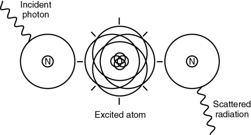
Compton effect
The Compton effect occurs at energy levels throughout the diagnostic x-ray range of 40 to 125 kVp. The incoming x-ray photon interacts with an outer orbital electron of an atom, removing it from the atom (ionization), and then proceeds in a different direction. The majority of the photon’s energy is converted into a new photon of scatter radiation (Fig. 9-2). This new photon has less energy than the incoming primary beam photon and therefore a longer wavelength. It also travels in a new direction. Compton scatter travels in all directions. If it is directed back toward the x-ray tube, it is termed backscatter. Most of the photons that are scattered will scatter in a more forward direction. As the kVp is increased, Compton interactions are increased.

Photoelectric effect
The photoelectric effect is similar to that which forms characteristic radiation in the x-ray tube (see Chapter 5). In this case, however, the incoming energy is an x-ray photon interacting with an atom in the body rather than an electron interacting with the tungsten anode.
In a photoelectric interaction, the incoming photon from the primary beam collides with an inner orbital electron of an atom. The photon is totally absorbed in the process and creates an absorbed dose in the patient. The electron’s departure leaves a “hole” in the orbit, which is filled by an electron from an outer shell. The difference in binding energy between the two shells is emitted as a new x-ray photon (Fig. 9-3). This photon is referred to as a characteristic photon and is considered secondary radiation because it is radiation actually produced in the body. The photon will have a new direction. Its energy will be less than that of the primary photon. Photoelectric interactions are less prevalent in the diagnostic energy range than Compton interactions. The likelihood of a photoelectric interaction is determined by both the kVp level and the electron-binding energy of the atom in which the interaction occurs.

Because no part of the energy of the incoming photon exits the atom, photoelectric interactions are sometimes referred to as true absorption. In this text, references to scatter also apply to secondary radiation formed by the photoelectric effect. As kVp is increased, photoelectric effect is decreased. Note that this is the opposite of the Compton effect. In the diagnostic range of kVp used (50 to 100 kVp), the majority of radiation interactions with the body are Compton interactions.
Radiographic effect of scatter radiation
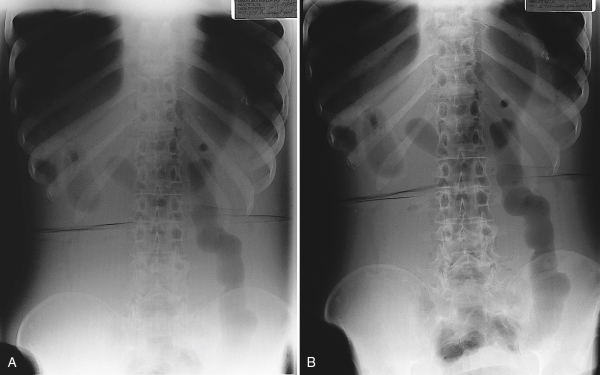
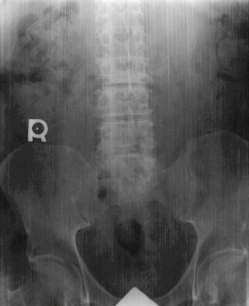
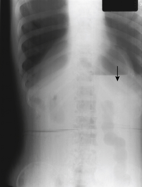
The production of scatter radiation during an exposure results in fog on the radiograph. Fog is unwanted exposure to the image. It does not strike the IR in a pattern that represents the subject, and it contributes nothing of value to the image. This fog produces an overall increase in radiographic density. The result is also a reduction in radiographic contrast, as stated in Chapter 7. Although increased density in the darker areas of the image is scarcely noticeable, areas that would otherwise be bright or white will instead be gray because of the fog. The intermediate gray tones will appear more similar to each other, which makes it difficult to distinguish recorded detail within those portions of the image that have similar tissue densities. In other words, scatter radiation creates fog that reduces both contrast and the visibility of detail (Fig. 9-4).
Factors affecting quantity of scatter radiation fog
Four primary factors directly affect the quantity of scatter radiation fog on the radiograph (Box 9-1): volume of tissue, kilovoltage, density of the matter, and field size.
 Box 9-1
Factors Affecting Scatter Radiation Fog
Volume of tissue
The primary scatter consideration is the volume of tissue irradiated. The thicker or larger the body part is, the greater are the scatter and the fog. When there is a greater quantity of tissue in the path of the x-ray beam, there will be greater absorption of the x-ray beam and more interactions that produce scatter radiation. The volume of tissue irradiated is determined by the thickness of the subject and the size of the radiation field. When the subject is more than 10 to 12 cm in thickness, the amount of fog becomes objectionable unless the field size is very small.
Because a thicker subject requires a greater quantity of exposure, there will be more primary x-ray photons and more interactions. This is another reason why there will be more scatter radiation when the thickness of the subject is increased.
Kilovoltage
Kilovoltage also affects the quantity of scatter radiation that reaches the IR. Higher kVp results in more scatter radiation fog. When high-energy photons interact with matter, the scatter radiation that is produced is also of a higher energy. This high-energy radiation is better able to escape the subject without being reabsorbed and so is more likely to cause fog on the radiograph.
Density of absorbing matter
The density or atomic number of the absorbing matter also influences the quantity of scatter radiation fog. The denser the body part, the less the scatter. This is because there is more photoelectric effect. A very dense body part (higher atomic number), such as a bone, will absorb a large quantity of primary radiation. The prevalence of scatter radiation in radiography indicates that there must be some matter that produces scatter radiation and permits it to escape. In fact, this is the case with all matter that is similar in density to water. Because the human body is largely made up of water, the patient is the principal source of scatter radiation in radiography.
Field size
Maintaining the correct field size through collimation is one of the most important things a limited operator can do to control scatter radiation. As collimation is increased, or made larger, scatter radiation fog increases. Collimation should be restricted to only the body part being radiographed. This is also important because the smaller the field size, the fewer body parts are subjected to x-rays and the smaller the dose is to the patient.
Controlling scatter radiation fog
From this discussion, it is clear that scatter radiation fog becomes increasingly objectionable as the thickness of the subject increases. To obtain diagnostic quality radiographs of the trunk of the body, it is absolutely essential to employ some means of limiting the fog effect on the IR. The principal method for reducing scatter radiation fog is the use of a radiographic grid. A grid is used when the body part becomes greater than 10 to 12 cm in thickness or kVp settings are greater than 60. Additional strategies include beam restriction and reduction of kVp.
Grids
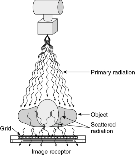
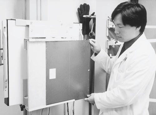
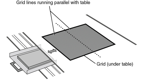
A grid is a device placed under the table between the patient and the IR (Fig. 9-5). It has the appearance of a thin metal plate (Fig. 9-6) and is constructed of tiny, tissue-thin lead strips, placed on edge. The lead strips are held in place by a radiolucent interspacing material, usually aluminum. Because they are aligned to the x-ray beam, the lead strips tend to absorb scatter radiation while permitting remnant radiation to pass through (Fig. 9-7).

The effectiveness of a grid is determined by the grid ratio, that is, the relationship between the height of the lead strips and the width of the spaces between them (Fig. 9-8). This ratio determines how much variation in the direction of the incoming photon is allowed without the photon being absorbed by the grid. The higher the ratio, the less variation is permitted and the greater is the efficiency of the grid in absorbing the unwanted photons. Typical grid ratios range from 5:1 to 16:1. Table 9-1 lists common grid ratios and their usual applications. The x-ray table and upright unit will have a built-in grid that cannot be changed. Different grids are used for mobile x-ray projections. Limited operators may use a grid IR when taking an x-ray on a patient in a wheelchair or on a cart.
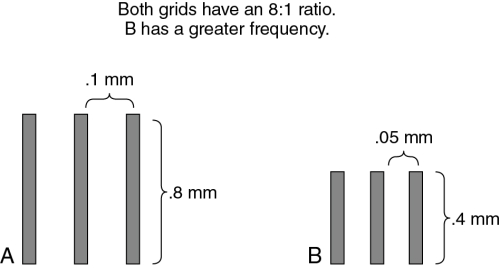
Table 9-1
| Ratio | Application |
| 5:1 and 6:1 | Grid cassettes, mobile radiography |
| 8:1 | General purpose |
| 12:1 | General purpose, chest radiography |
| 16:1 | High-kilovoltage radiography |
As seen in Fig. 9-8, grids with the same ratio may have many strips close together or fewer strips farther apart. The number of lead strips per inch is called the grid frequency. Grid frequencies range from 60 to 196 lines/inch.
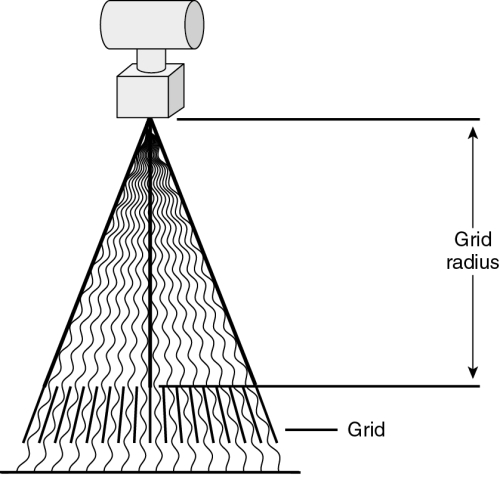
Grids for general-purpose use are called focused grids because the lead strips are aligned in the direction of the diverging primary x-ray beam (Fig. 9-9). The lead strips of a focused grid are precisely aligned with the x-ray beam at a specific source–image receptor distance (SID), which is called the grid radius. Because the alignment does not need to be exact for the useful photons to pass through the grid, there is a range of distances within which the grid will not absorb an undue amount of useful radiation. This is referred to as the focal range of the grid. The SID employed with a grid should always be within the grid’s focal range. The most commonly used SIDs are 40, 48, and 72 inches. Each usually requires a different grid with a suitable focal range. Grids with extra-long focal ranges are now available, however. Some have a focal range of 40 to 72 inches.
Each grid has a label indicating its ratio, its frequency, and its radius or focal range. This label is placed on the side of the grid that faces the x-ray tube when the grid is in use. There is usually also a line down the middle that indicates the long axis of the lead strips and the grid’s focal center.
Because the grid absorbs some useful radiation, the radiographic image includes an image of the grid itself. This grid image is called grid lines or grid striping (Fig. 9-10). Grid lines that appear on the image are objectionable and can reduce recorded detail. Two methods are employed to prevent objectionable grid lines: the grid may be moved during the exposure or the grid may have a very high frequency (i.e., many fine lines very close together).
A moving grid is called a Bucky, so named after Dr. Gustav Bucky, who invented it in 1913. A Bucky is a part of a radiographic table (Fig. 9-11) or an upright cassette holder. The Bucky grid is mounted in a frame that incorporates a small motor. The motor causes the grid to oscillate back and forth rapidly during an exposure. This movement blurs the image of the grid lines, making them invisible on the radiograph. The Bucky device also includes the IR tray that holds the cassette in place when making Bucky exposures. A table Bucky has rollers that allow it to be moved along a track under the tabletop. This permits placement of the Bucky and the film at any location along the length of the table. Bucky grids typically have a ratio of 12:1 to 16:1 and a frequency of 85 to 103 lines/inch.
A high-frequency grid that does not move during the exposure is called a stationary grid. Such a grid produces grid lines, but the lines are very tiny and close together and are not readily seen at a normal viewing distance. Their appearance is acceptable because they are almost invisible and do not adversely affect the diagnostic quality of the image. Stationary grids may be part of a Bucky-like device in the radiographic table, and they are often used in upright cassette holders called grid cabinets. Stationary grids for permanent installations typically have a ratio of 8:1 or 12:1 and a frequency of at least 103 lines/inch.
Portable stationary grids come in various sizes and may be attached to a cassette when needed in locations other than the permanent installations. A grid cassette is a special cassette with a grid built into the front side. Both portable grids and grid cassettes are used for mobile and surgical radiography and for special applications when the patient cannot be positioned on the table or at the upright grid cabinet. Grid cassettes typically have lower ratios than the grids used in permanent installations. Ratios of 5:1, 6:1, and 8:1 are common. Grid cassettes should be clearly marked and kept in a separate place from the regular cassettes. They must never be used in the Bucky.
Grids are precision instruments and are very expensive to replace. Special care must be taken to ensure that they are not damaged by dropping, striking, or bending. Such damage causes the lead strips to become misaligned, which makes the grid useless.
Grid cutoff
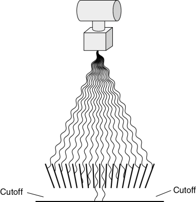
Focused grids are designed to allow the passage of radiation that is aligned with the lead strips. Any misalignment of the primary x-ray beam will result in undesirable absorption of useful radiation by the grid. Excessive absorption of useful radiation by the grid is called grid cutoff. Grid cutoff appears as decreased radiographic density on the side of the image (Fig. 9-12).
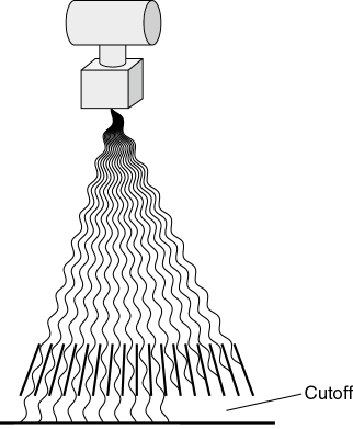
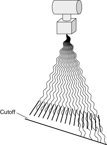
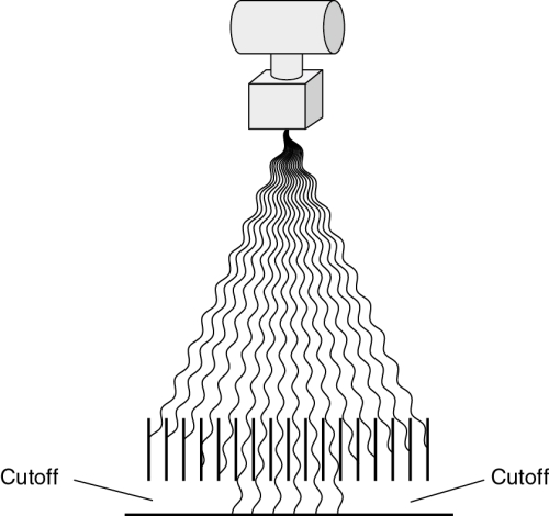
No grid cutoff occurs when the x-ray beam is correctly aligned with the grid (Fig. 9-13). Grid cutoff occurs when the x-ray tube is centered to one side of the grid rather than to the focal center line (Fig. 9-14). Cutoff also occurs when the x-ray tube is angled toward one side of the grid, rather than perpendicular to its center. The same effect is encountered if the grid is tipped side to side in relation to the primary beam (Fig. 9-15). Both of these problems involve only centering and angulation with respect to the sides of the grid. Cutoff does not result when the x-ray tube is off center lengthwise or angled along the length of the lead strips.

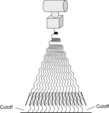
When a grid is used at a distance outside its focal range, cutoff will occur on both sides of the film (Fig. 9-16).
When the grid is reversed—that is, the wrong side is facing the x-ray tube—grid cutoff prevents most of the primary radiation from reaching the film (Fig. 9-17). A film taken with the grid reversed will show exposure only in a line down the center. The remainder of the film will be very light and streaked with grid lines.
Grid cutoff is prevented by ensuring that the x-ray beam is always properly aligned with the center of the grid at the appropriate distance. The precision required when aligning the x-ray beam to the grid is determined by the grid ratio. The higher the grid ratio, the more precise the alignment must be. This is why relatively high-ratio grids are used only in permanent installations where alignment is easily maintained. Lower-ratio grids are used for bedside radiography and other portable applications where it is more difficult to ensure precise alignment.
Specialty grids
Specialty grids are available for special situations but are not suitable for general-purpose use. A grid with strips that are parallel to each other, rather than focused, is called a parallel grid (Fig. 9-18). The radius of a parallel grid is infinity. Parallel grids can be used for radiography at very long SIDs because the useful portion of the x-ray beam is nearly perpendicular to the grid when the distance is great. They are available only in lower ratios. Parallel grids are also used in fluoroscopic spot film devices.
Another type of specialty grid is the crosshatch grid, sometimes called a crossed grid. This is actually a composite of two grids with the lead strips at right angles to each other (Fig. 9-19). A crosshatch grid is desirable because it has an effective ratio that is greater than the ratios of the two grids combined. For example, a crosshatch grid made of two 8:1 grids would be more efficient at preventing scatter radiation fog than a regular 16:1 grid, but would have the alignment flexibility of an 8:1 grid. The limitation of the crosshatch grid is that it produces unacceptable grid cutoff when the x-ray tube is angled. It is useful only for procedures done with the central ray perpendicular to the grid and the film. This consideration makes it unsuitable for general use.

Field size and collimation
Because field size and collimation significantly affect the volume of tissue irradiated, a reduction in field size will decrease the scatter radiation fog on the radiograph. For this reason, the radiation field is collimated to expose only the area of clinical interest. Decreasing the collimation improves contrast even when a grid or Bucky is used because it decreases the quantity of scatter that penetrates the grid (Fig. 9-20). When fog compromises the ability to see specific details in a large body part, it is common to take a coned-down image (Fig. 9-21). This term refers to a radiograph of a very small area of the subject. Most coned-down images are taken using an 8- × 10-inch IR and a 5- or 6-inch square field. They are centered precisely to the area of interest. Coned-down images demonstrate increased contrast compared with images of the same anatomy seen within a larger field. When a specific area of interest is centered to the field, as in a coned-down image, the decreased distortion also improves image quality.

Collimator and central ray alignment
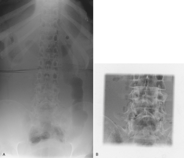
A quality control (QC) check is regularly performed on the collimator to ensure accuracy and to meet state and federal regulations. At the same time the collimator is tested, the x-ray beam alignment, or central ray alignment, is checked because in many instances it is the alignment of the tube that needs adjustment and not the collimator itself. This check is easily done with a collimator template and a beam alignment cylinder (Fig. 9-22). With the collimator test tool, an exposure is made with the template placed on the IR, and the light field is collimated to the indicated square. The standard control limit for the collimator is that the x-ray light field and the radiation field must be within ±2% of the SID. This means that at a 40-inch SID, the light field must be within 0.8 inch of the radiation field (Fig. 9-23).
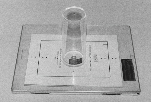
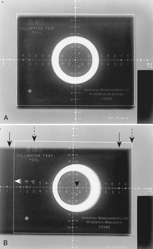
An efficient quality control check can be done when the collimator template and a beam alignment cylinder are used together. Both the collimator and the alignment can be checked at the same time. The beam alignment cylinder (see Fig. 9-22) is placed directly on the collimator template, and the alignment is checked with the same exposure. A small lead bead at the top of the cylinder should be aligned with the small bead at the bottom of the cylinder if the alignment is correct. The standard control limit for the tube’s CR beam alignment is that the tube must be mounted so that the x-ray beam is within 1 degree of perpendicular. Fig. 9-23 shows two radiographs from the collimator and beam alignment test.
Decreasing kilovoltage
When other methods fail to provide sufficient contrast, a decrease in kVp should be considered. Decreasing kVp increases contrast in two ways. First, this narrows the scale of contrast, as explained in Chapter 7. Second, lower kVp levels decrease the energy of the scatter radiation and decrease the fog, as explained earlier in this chapter. Of course, when kVp is decreased, radiographic density will also decrease. This requires an increase in milliampere-seconds to compensate. The mathematical calculations for maintaining radiographic density when changing kVp are discussed in Chapter 10. This change in exposure factors results in increased radiation dose to the patient, and so it should be used only when necessary. Caution should also be used when lowering the kVp because the body part may not be penetrated if the kVp is lowered too much.
Summary
When diagnostic x-rays are absorbed by matter, they are “scattered,” forming scatter and secondary radiation by means of coherent scattering, the Compton effect, or the photoelectric effect. The greatest quantity of scatter formed during routine radiography is caused by the Compton effect, which scatters photons in all directions. This scattered radiation causes fog on the radiograph, decreasing radiographic contrast and decreasing the visibility of detail. The fog level becomes objectionable when the thickness of the subject is greater than 10 to 12 cm.
Scatter radiation fog is controlled primarily by using either a stationary grid or a moving grid device called a Bucky. The grid ratio indicates the efficiency of the grid in cleaning up scatter radiation and the precision with which the x-ray beam must be aligned with the grid. When the x-ray beam and the grid are not properly aligned with each other, grid cutoff results. Other means for reducing scatter radiation fog include reducing the field size and decreasing kVp.