Chapter 13 Magnetic Resonance Imaging
Magnetic resonance angiography (MRA) is widely accepted for the majority of vascular imaging applications and is the modality of choice for many of them, particularly peripheral and renal arteriography.1–3 Gadolinium-based contrast-enhanced (CE) MRA yields high-quality spatial resolution images with relatively short acquisition times. Detailed comparison with other imaging technologies is beyond the scope of this chapter, but general advantages and disadvantages appear in Table 13-1. These become important for many applications such as aortography, where multiple modalities (e.g., computed tomography [CT] and MRA) are routinely diagnostic and capable of providing images for planning most interventions.
Table 13-1 Advantages and Disadvantages of Vascular Imaging Methods
| Method | Advantages | Disadvantages |
|---|---|---|
| MR | No ionizing radiation | Expensive hardware Acquisition requires technical expertise |
| CE | High signal from gadolinium-based agents Less nephrotoxic than comparable iodine-based imaging (CT) |
Nephrogenic systemic fibrosis can occur rarely in patients with severe renal insufficiency |
| Non-contrast | Eliminates toxicity concern | Longer acquisition times compared to CE protocol Increased risk of artifacts that are largely mitigated with CE-MRA |
| CT | Rapid, high signal, high-quality image acquisition Less technical expertise required compared to MR |
Ionizing radiation Nephrotoxicity of iodine |
| DSA | Intervention can be performed at time of diagnosis Highest spatial resolution |
Invasive Nephrotoxicity of iodine Projectional data may be inferior to volumetric acquisitions (CT, MR) that can be viewed in any plane |
| Sonography | No ionizing radiation Less expensive Flow information readily obtained Portable |
Better for superficial imaging Limited by artifacts from bone, air, and sonographic interfaces Lower CNR, SNR compared to CT and MRI Operator-dependent |
CE, contrast-enhanced; CNR, contrast-to-noise ratio; CT, computed tomography; DSA, digital subtraction angiography; MRA, magnetic resonance angiography; MRI, magnetic resonance imaging; SNR, signal-to-noise ratio.
Basic Principles
Magnetic resonance imaging (MRI) relies upon the inherent magnetic properties of human tissue and the ability to use these properties to produce tissue contrast. Magnetic resonance imaging detects the magnetic moment created by single protons in omnipresent hydrogen atoms. Because any moving electric charge produces a magnetic field, spinning protons produce small magnetic fields and can be thought of as little magnets or “spins.” When a patient is placed in the bore of a large magnet (i.e., MRI scanner), hydrogen protons align with the externally applied static magnetic field (B0) to create a net magnetization vector. On a quantum level, most protons will distribute randomly, either with or against the scanner’s B0. However, a slight excess of spins aligns with the field, causing net tissue magnetization. The time required for this alignment is denoted by the longitudinal relaxation time, T1. T1 variations between tissues is used to provide contrast.
Spinning protons wobble or “precess” about the axis of B0. The frequency of the wobble is proportional to the strength of B0. If a radiofrequency (RF) pulse is applied at the resonance frequency of the wobble, protons can absorb energy and jump to a higher energy state. This RF pulse deflects the protons, creating a new net magnetization vector distinct from the major axis of the applied magnetic field. The net magnetization vector tips from the longitudinal to the transverse plane (transverse magnetization). The protons are “flipped” by the RF pulse, and the net magnetization vector is defined by a “flip angle.” The stronger the RF pulse applied, the greater the angle of deflection for the magnetization. Common flip angles for spin echo are 90° and 180°. For gradient echo (GRE) MRI, flip angles typically range between 10° and 70°. After the RF pulse tips the spinning protons out of alignment with the main magnetic field, new protons begin to align with the main magnetic field at a rate determined by the T1 relaxation time.
Energy is given off as the spins move from high to low energy states. The absorbed RF energy is retransmitted at the resonance frequency and can be detected with RF antennas or “coils” placed around the patient. These signals are compiled, and after mathematical processes become the MR images. Proton excitation with an externally applied RF field is repeated at short intervals to obtain signals. This MR parameter is referred to as repetition time (TR). For conventional MRI, TR is typically 0.5 to 2 seconds, whereas for MRA, TR ranges from 30 to less than 5 milliseconds. When the spins are tipped to the transverse plane, they all precess in phase. The speed of wobbling depends on the strength of the magnetic field each proton experiences. Some protons spin faster while others spin slower, and they quickly get out of phase relative to one another. Throughout the dephasing process, the MR signal decays. This loss of phase is termed T2 relaxation time or transverse relaxation. T2, like T1, is unique among tissues and is used for image contrast. In addition to the intrinsic T2 of tissue, inhomogeneity of B0 results in rapid loss of transverse magnetization. The relaxation time that reflects the sum of these random defects with tissue T2 is called T2*. To obtain an MRI signal, these spins must be brought back in phase and produce a signal or echo. The time at which it happens is referred to as echo time (TE). In spin echo imaging technique, the echo is obtained by using a refocusing 180° RF pulse, after which the spins begin to dephase. Another 180° RF pulse can be applied to generate a second echo and so on. Signal loss at longer echo times reflects tissue T2. In GRE imaging, the echo is obtained by gradient reversal rather than RF pulse. Because this includes effects from tissue homogeneity, TE-dependent signal loss reflects T2*. Recently, GRE sequences (balanced GRE steady-state free precession [SSFP]) have been developed that are insensitive to magnet field inhomogeneities and reflective of actual tissue T2.
Longitudinal and transverse magnetizations occur simultaneously but are two different processes that reflect properties of various tissues in the body. Since T1 measures signal recovery, tissues with short T1 are bright, whereas tissues with long T1 are dark. Fat has a very short T1. In contrast, T2 is a measure of signal loss. Therefore, tissues with short T2 are dark, and those with long T2 are bright. Simple fluids, such as cerebrospinal fluid and urine, have long T2. To differentiate between the tissues based on these relaxation times, MR images can be designed to be T1-weighted, T2-weighted, or proton-density weighted. Exogenous contrast such as gadolinium-based agents are routinely used to alter tissue conspicuity. Spatial encoding of signals obtained from tissues is required for imaging. Additional external time-varying magnetic fields are applied to spatially encode the MR signal. Spatially dependent gradients are used to locate the MR signal in space. In two-dimensional (2D) MRI, these are slice-selection, frequency-encoding, and phase-encoding gradients. In three-dimensional (3D) MRI, the slice-selection gradient is replaced by a second phase-encoding gradient.
Magnetic resonance echoes are digitized and stored in “k-space” composed of either two axes (for 2D imaging) or three axes (for 3D imaging). K-space represents frequency data and is related to image space by Fourier transformation. An important feature of k-space is that tissue contrast is determined by the center of k-space (central phase encoding lines), whereas the periphery of the k-space encodes the image detail. The order in which k-space lines are collected can be varied, strongly influencing tissue contrast. For example, in CE-MRA, the central contrast-defining portion of k-space may be acquired early in the scan (centric acquisition) during peak intraarterial contrast concentration to maximize arterial contrast. In addition to simple line-by-line k-space acquisition schemes, more complex schemes have been described. In spiral imaging, data acquisition begins at the center of k-space and spirals to the periphery. Slice-selective gradients applied along the z-axis will form axial images. Those along the y-axis will yield coronal images, and the x-axis gradients will provide sagittal images. An oblique slice can be selected by a combination of two or more gradients.
Magnetic Resonance Angiography Techniques
Magnetic resonance imaging relies on selective imaging of moving blood where signals from blood vessels are maximized, whereas signals from the stationary tissues are suppressed. Algorithms then enable reformatted images similar to those found in conventional x-ray angiography (Table 13-2).
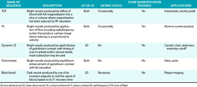
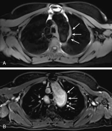
Magnetic resonance angiography methods can depict blood as either black or white. For those “black-blood” methods that use standard spin echo (SE) sequences (Fig. 13-1A), the excitation RF pulse is applied at 90° and followed by a refocusing pulse at 180°. If the imaging slice cuts across a vessel, then depending on the flow velocity and time interval between the pulses, the blood volume originally excited by the first pulse may not “see” the second pulse. This results in a black-appearing signal void in the vessel lumen. The use of thin sections or long echo times can further emphasize this flow void. This technique allows detailed examination of arterial wall morphology. Fast spin echo (FSE) sequences, in which a long train of echoes is obtained by use of repeated 180° pulses, produce images more rapidly. The double inversion recovery (DIR) FSE offers a new approach to enhance black-blood sequences. The technique uses two consecutive inversion pulses: the first nulls or blackens the blood everywhere in the coil, and the second restores magnetization in the slice being imaged. Between these pulses and image production, blood within the slice is replaced by nulled blood from outside. This produces more reliable black blood than conventional approaches, making this sequence ideal for examining wall thickness, dissection flaps, and the presence of mural thrombus or inflammation.4 This provides a clear advantage over traditional x-ray angiography.
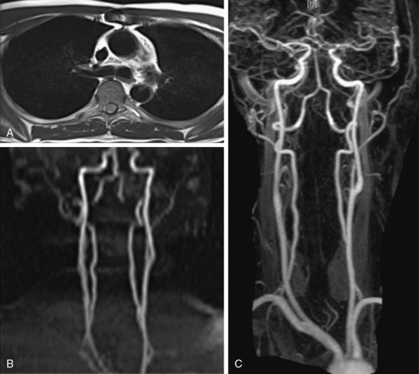
Figure 13-1 “Black-blood” and “bright-blood” imaging techniques. A, Cross-sectional T1-weighted image of ascending and descending aorta; lumen appears black. B, Time-of-flight (TOF) image of carotid-vertebral system. C, Maximum-intensity projection (MIP) reconstruction of arterial phase of contrast-enhanced magnetic resonance angiography (CE-MRA) images in same patient shows normal carotid-vertebral arteries at higher spatial resolution than corresponding TOF acquisition.
“Bright blood” MRA techniques use GRE sequences and are generally divided into those measuring signal amplitude (time-of-flight [TOF]) and those based on phase effects (phase-contrast [PC]). In each GRE sequence, a single RF pulse is applied in short time intervals, eliminating signal loss due to flow void. The stationary protons occupying a given tissue slice do not have sufficient time to relax to their equilibrium state.
TOF-MRA techniques depend on the inflow of unsaturated protons in blood from outside the field of view (FOV) into the stationary tissue within a section already saturated by its exposure to repeated RF pulses. These “saturated” protons are unable to contribute signal to the image. The signals in the stationary tissues of GRE images used in MRA are therefore typically low. The “unsaturated” protons in blood flowing into the imaging plane have not experienced the RF pulses and yield maximum signal. The unsaturated blood appears bright compared to background tissue (Fig. 13-1B). The time required for blood to flow through an image slice and its effect on the resulting signal is known as TOF. Saturation of signals can occur in vessels with slow-moving blood as a result of repeated RF excitation in the acquisition plane. This can create artifacts in vessels with stenotic lesions or reduced blood flow.
Time-of-flight techniques can be obtained in 2D or 3D. The 2D TOF utilizes multiple sequentially acquired, overlapping thin slices to form an image. The patient is instructed to hold his/her breath to minimize motion artifact. However, spatial misregistration may occur if patients cannot hold their breath at the same level each time. Thus, only one or two slices are typically acquired per breath-hold. 2D TOF has good sensitivity for identifying vessels with slow flow because blood must move only 3 to 5 mm to refresh a slice. 3D TOF consists of GRE acquisition of a volume into which blood is flowing. The advantage of this technique is higher signal-to-noise ratio (SNR) and improved resolution. The thick volumes of tissue imaged require rapid flow to fully refresh signals within the arteries. The technique is flow dependent and superior in vessels with rapid steady flow without respiratory motion. Additional saturation pulses can be applied to eliminate signal from veins. Segmented GRE sequence with cardiac triggering can be used to eliminate arterial pulsation artifacts.
A successful TOF image requires the section to be thin enough to allow for sufficient inflow between RF pulse repetitions, but thick enough to ensure adequate SNR and anatomical coverage. Section thickness of 3 to 4 mm is used for large vessels, and 1 to 2 mm for smaller vessels. Spatial presaturation pulses are applied above or below the imaged slice or volume to eliminate unwanted signal from arteries or veins, depending on which part of the vascular tree is being imaged. Optimal TR for TOF is 20 to 50 milliseconds. Short TR keeps background tissues saturated, but it must be long enough to allow for satisfactory inflow of unsaturated blood between successive repetitions. The best flip angle is usually 30° to 60°. With phasic flow in the extremities, systolic flow signal may be increased (because of greater transverse magnetization created), and distal flow may be decreased, creating view-to-view intensity changes and phase artifacts from pulsatile variations. This pulsation artifact is greatest at higher flip angles. Cardiac gating can be used to minimize these artifacts at the expense of increased imaging time.
Whereas TOF uses differences in signal amplitude to differentiate between stationary and flowing spins, the PC technique observes the phase shifts of signals. Moving spins experience different phase shifts in the presence of the applied magnetic fields used in MRA. Strength and orientation of the applied magnetic field are varied to encode different phase shifts for flowing protons relative to stationary protons. The faster the spins are moving, the greater their phase shift, and protons of flowing blood may be discriminated from stationary protons. The phase shifts result in a contrast between moving and stationary tissues and form the basis for PC imaging. Pairs of images are acquired that have different sensitivities to flow and are then subtracted to cancel background signal, leaving only the signal from flowing blood. Phase shift is proportional to velocity, allowing flow quantification with this modality. Phase-contrast acquisitions may be acquired in two or three dimensions; although used rarely in angiography today, Phase-contrast offers a reliable way to quantify amount and direction of flow. It requires long imaging times: two data sets in each direction are acquired by using flow-encoding gradients of opposite polarity, and up to three measurements in the orthogonal planes are needed to image flow in all directions.
Visualization of the arterial system with PC and TOF is adequate5 but has limitations. Acquisition times can be long and prevent imaging within the time span of a single breath-hold. This increases the chance of movement artifacts. Some of the limitations are caused by flow-related artifacts such as in-plane saturation and phase dispersion. Flow-based imaging also has limits in areas of slow flow, such as aneurysms. Overgrading of stenotic lesions is most commonly a manifestation of signal loss in the areas of complex flow. Undergrading is a matter of inadequate spatial resolution. Complex turbulent flow patterns in areas of stenoses can create signal loss and mimic a critical lesion. This is due to “intravoxel dephasing.” An accelerated flow across a stenosis consists of a wide distribution of velocities and thus a large distribution of proton phases. In the smallest volume element, a “voxel” of the image, this distribution of phases can result in cancellation rather than coherent addition of signals, accounting for the presence of signal voids at the site of stenosis. A short TE minimizes flow-phase dispersion artifacts. Phase dispersion is further decreased when voxel size is minimized using thin sections. Small voxels and short TE are most easily obtained with 3D TOF methods. The biggest drawback of the thick volumes used with 3D techniques is that slow or recirculating flow can become saturated. The MOTSA (multiple overlapping thin-slab acquisitions) technique of sequential 3D TOF gives better flow enhancement than single-slab 3D TOF techniques and less dephasing than 2D techniques. However, the need for substantial overlap of adjacent slabs increases acquisition time.
Contrast-Enhanced Magnetic Resonance Angiography
The introduction of CE-MRA has revolutionized MRA.6,7 This technique overcomes many of the limitations of traditional bright blood modalities: respiratory motion artifacts, poor SNR, and flow and saturation-related artifacts (Fig. 13-1C). Gadolinium increases the signal intensity of blood on contrast-enhanced 3D T1-weighted (spoiled) GRE images. Blood contrast is not flow dependent. It is determined by the concentration of contrast agent within the arterial system while imaging data are being collected. Reliable images can be acquired irrespective of whether flow is laminar, turbulent, or stagnant. This technique acquires large-volume data sets in coronal or sagittal orientation within a single breath-hold during the first pass of the contrast material. The contrast agent, gadolinium, is a heavy metal but becomes inert when bound to a chelator. Intravenous (IV) administration of gadolinium-diethylenetriamine pentaacetic acid (DTPA) results in a marked reduction of the T1 or longitudinal relaxation time of blood, therefore reducing the effects of spin saturation. Signal reduction is also problematic in 3D TOF sequences. Moreover, the very short TE reduces spin dephasing and allows accurate evaluation of vascular stenoses.
Multiple refinements have resulted in a technique that is much faster than TOF-MRA. The development of high-performance gradient systems with ultra-short repetition TR and TE has shortened acquisition time in CE-MRA to allow imaging within a single breath-hold and minimize motion artifacts. Administration of agents shortening T1 allows selective visualization of contrast-containing structures and better visualization of circuitous collaterals. Digital subtraction, spoiling, and fat saturation techniques suppress background signal and enhance signal from the contrast agent in the vessels. The subtracted data sets can be postprocessed to provide 3D projectional images. CE-MRA still provides a luminogram, and conventional or FSE images are needed for a complete study so that true lumen diameter and presence of thrombus can be established.
Optimal images are generated when gadolinium concentration is highest in the vessel of interest. To make blood bright compared to background tissues, the gadolinium bolus must be administered in a way that ensures the majority of the contrast to be present in the arterial tree. This requires exact timing of the arrival of the gadolinium bolus. Acquisition prior to contrast arrival creates a “ringing” artifact, whereas late acquisition creates venous and tissue enhancement, contaminating the arterial signal. This is especially problematic in MRA of the extremities, where the images are obtained in multiple segments. Contrast transit time can be affected by low cardiac output, valvular regurgitation, large abdominal aneurysms, and flow-limiting stenoses. Proper timing can be achieved by empirical estimation of transit time or a test bolus in the anatomical field of interest. Alternatively, with automated triggering, a pulse sequence can be designed to sense the arrival of contrast and automatically trigger image acquisition. Magnetic resonance fluoroscopy allows the user to visualize arrival of the contrast bolus directly on the image and manually trigger the start of the scan. Areas that require higher spatial resolution, such as the lower extremities, also need larger doses of contrast for longer acquisition times.
Imaging during the arterial phase of gadolinium infusion takes advantage of higher arterial SNR and eliminates overlapping venous enhancement. This is a brief moment in time, but several methods allow slower MR image acquisition to capture that moment. The phase reordering (mapping k-space) technique acquires central k-space data (i.e., the low spatial frequency data) when contrast concentration is high in arteries but lower in veins. This allows a relatively long MR acquisition to achieve the image contrast associated with the shorter arterial phase of the contrast bolus. It is critical to time the contrast bolus to achieve maximum arterial gadolinium concentration during acquisition of central k-space data.
CE-MRA is limited by venous and soft-tissue enhancement. Contrast media not only passes into venous structures, dependent on the arteriovenous transit time of the tissue, but also rapidly leaks out of the vascular compartment, creating significant tissue enhancement. New “blood pool” agents, which are currently undergoing clinical trials, are retained within blood vessels and selectively enhance the blood pool on T1-weighted MR images. These use either gadolinium compounds that bind to albumin, or are large enough to stay within the vascular space or ultra-small iron particle. Another agent, gadobenate, has a higher T1 relaxation time because of its capacity for weak and transient interaction with serum albumin. This may enhance vascular signal intensity and thus increase diagnostic efficacy at doses comparable to those used for current gadolinium agents. It is approved for imaging use in Europe but is under clinical investigation in the United States. It provides a higher and longer-lasting vascular signal enhancement in the abdominal aorta compared with gadolinium, which does not interact with proteins.8
Gadolinium-based contrast has a very favorable safety profile. However, gadolinium is nephrotoxic. For patients with underlying chronic renal insufficiency, gadolinium chelates can cause acute renal failure. Nephrogenic systemic fibrosis (NSF) is linked to gadolinium-based contrast agents9 and largely involves the skin, though it may also affect the muscle, joints, or internal organs such as the lungs, liver, and heart in patients with renal failure. Nephrogenic systemic fibrosis occurs in patients with severe renal disease who are exposed to high doses of gadolinium agents, or in patients who receive multiple standard doses of contrast agents in a short period of time. The reported prevalence of NSF among patients with glomerular filtration rate (GFR) less than 30 mL/min is 3% to 5%.10 Therefore, the MR protocol should aim to minimize contrast volume, especially in patients with moderate to severe renal failure.11
Metal objects, such as surgical clips, lead to susceptibility artifacts in MRA. The increasing use of stents has important implications for MRA. Cavagna et al. evaluated CE-MRA of seven stent types in the aortic, iliac, and popliteal positions.12 Few of the commonly used stents permitted visualization of the lumen. Susceptibility artifact results in significant signal loss that can preclude proper visualization of the stent lumen even with gadolinium-enhanced MRA. Some nitinol, tantalum, or polytetrafluoroethylene (PTFE)-based devices, on the other hand, cause less artifact on CE-MRA.
Postprocessing Techniques
Magnetic resonance data can be viewed as source images or be displayed in projections with any orientation. Image postprocessing allows reformation in any desired plane to improve conspicuity of overlapping vessels (Table 13-3). The origins of the left common carotid artery (CCA) and left subclavian artery, for example, can overlap in coronal projections, whereas the origins of the right subclavian artery and right CCA can overlap in some oblique views. The renal ostia are usually best seen in either coronal or slightly oblique view. The celiac axis and superior mesenteric artery (SMA) are best depicted on sagittal projections. One advantage of MR versus digital subtraction angiography (DSA) is that the latter may require multiple injections to assess the origins of these vessels. The details of image interpretation are beyond the scope of this review, but source image data, multiplanar reconstruction (MPR), maximum-intensity projection (MIP), and volume rendering (VR) are used (Fig. 13-2). Source images are the initial reconstructions and should be used for problem solving and to confirm findings. Interpretation often begins with a vascular survey using MPR and MIP data sets. Multiplanar reconstructions are very useful in volumetric acquisitions because the desired imaging plane can be prescribed to enhance vascular separations. Subtracted MIPs are routinely created from CE-MRA. The noncontrast (mask) images are subtracted from the enhanced images, and resulting high SNR data sets undergo projection of maximum intensity. By performing the projections of all angles around the z-axis of the patient, the data sets can be viewed in cine. These projections are referred to as rotating MIPs.
Table 13-3 Types of Postprocessing Techniques
| Technique | Description |
|---|---|
| MPR | Production of cross-sectional images in planes different from acquisition plane |
| MIP projection | Production of full- or partial-volume images along any desired axis from a stack of image slices |
| Volume rendering | Manipulation of MRI slices to produce full volumetric images; structures segmented for viewing by application of intensity thresholds and removal of unwanted structures |
MIP, maximum intensity projection; MPR, multiplanar reconstruction; MRI, magnetic resonance imaging.
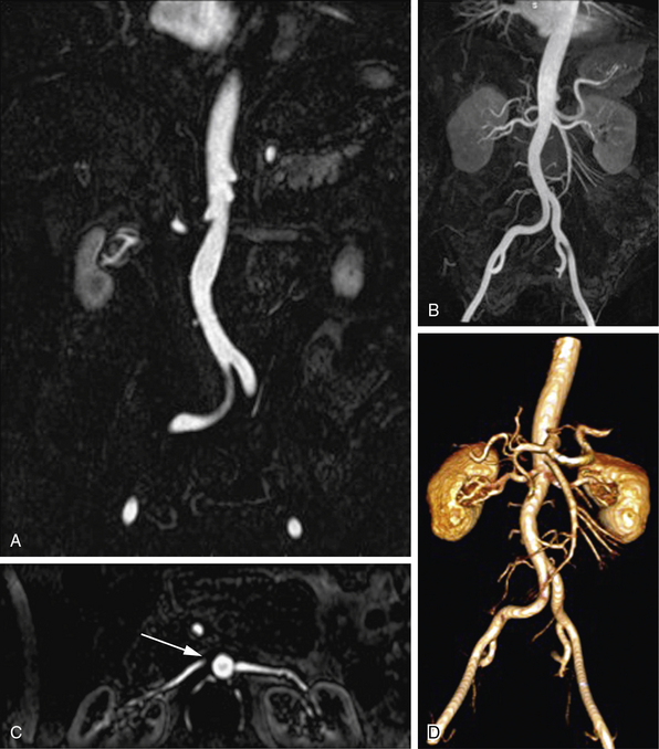
Figure 13-2 Postprocessing techniques; contrast-enhanced magnetic resonance angiography (CE-MRA) of abdominal aorta and branches.
A, Coronal thin-section image of abdominal aorta. Summation of these images, projected with maximum intensity, is used for (B) coronal maximum-intensity projection (MIP) that includes normal renal and mesenteric arteries. C, Axial multiplanar reconstruction (MPR) image at level of left renal ostium does not include entire extent of both renal arteries, giving false impression of a proximal right renal artery occlusion (arrow). D, Three-dimensional volume-rendered (3D-VR) image shows entire course of abdominal aorta and its branches.
Clinical Applications
Extracranial Carotid and Vertebral Arteries
Atherosclerosis, dissection, and inflammatory diseases affect the extracranial carotid and vertebral arteries. Time-of-flight methods (2D and 3D) have been largely replaced by CE-MRA because CE-MRA allows imaging of the entire course of these vessels (Fig. 13-3). A problem with TOF imaging is turbulent flow at or near the carotid bifurcation where most of the lesions occur; this may lead to overestimation of lesion severity. Gadolinium-enhanced MRA has greater SNR than noncontrast imaging, is less sensitive to intravoxel dephasing from turbulence, and does not have signal loss from saturation effects. Phase-contrast sequences can supplement anatomical data for flow direction or quantification.
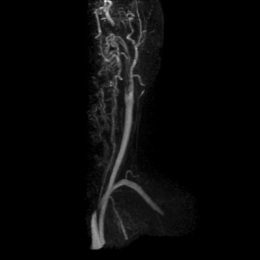
Figure 13-3 Carotid artery disease.
Left internal carotid artery (ICA) dissection resulted in a thrombotic occlusion of proximal vessel. Internal carotid artery reconstitutes more distally.
Transcranial flow has a rapid arteriovenous transit time, and thus venous contamination can limit image quality; therefore, time-resolved imaging may be required. Assessing the test characteristics of carotid MRA is challenging because technologies evolve, and the patients and methods are both heterogeneous. In a 41-study meta-analysis, carotid CE-MRA had high sensitivity (94%) and high specificity (93%) for diagnosis of severe (70%-99 %) carotid artery stenosis.13 The sensitivity and specificity of CE-MRA for ostial stenosis also is very high.14
The intimal flap of CCA dissection can be visualized with either CT or MRA. For a patient with poor or uncertain hemodynamic stability, CT is the preferred modality because it is more rapid and has better patient monitoring capabilities. However, MR is preferred for stable patients, since it does not impart ionizing radiation to the thyroid gland for either initial or follow-up studies.
For vertebral artery dissection, MRA can detect the level of stenosis or obstruction and distinguish residual flow from intramural hematoma.
Thoracic Aorta and Its Branches
Both CT and MRI provide comprehensive imaging of the aorta. Single breath-hold 3D CE-MRA imaging of the thoracic aorta (Fig. 13-4) is typically performed with electrocardiographic (ECG) gating to eliminate pulsation artifact.
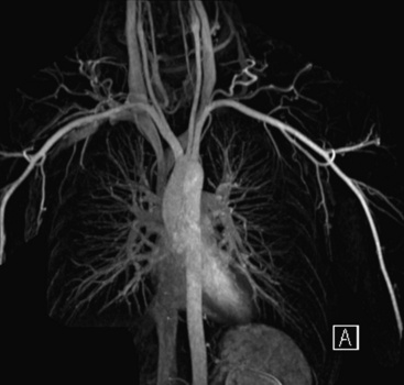
Figure 13-4 Maximum-intensity projection (MIP) image shows normal thoracic aorta and origin and course of supraaortic vessels.
Aortic dissection
A properly performed modern MRA is 100% sensitive for dissection and intramural hematoma.15 The true and false lumens, location and extent of the intimal tear, and the relationship of the tear to the branch vessels are readily tracked in multiple planes. Cine images of the proximal aorta can identify aortic regurgitation complicating type A dissection (Fig. 13-5). Delayed phase images allow identification of intramural hematoma, ulceration, and complications including rupture. On T1-weighted SE sequences, intramural hematoma is seen as a concentric thickening of the wall, with increased intramural signal intensity.16 Inflammatory changes are seen as arterial wall thickening and enhancement. When used with clinical parameters and other testing (e.g., blood pressure changes), MRA is useful to triage patients into either medical or surgical management options.17
Thoracic aortic aneurysm
Aneurysm imaging should consider slow blood flow through the lesion. Magnetic resonance angiography can demonstrate the location and size of an aneurysm, presence of a mural thrombus, and the relationship of the aneurysm to the branch vessels. Because MIP images from 3D CE-MRA are designed to highlight the lumen of the aorta, the source (including noncontrast) images should be evaluated to determine the extent of mural thrombus and the actual aneurysm size for accurate measurements. Time-resolved imaging shows delayed enhancement from slower flow.18 Patients with a clinically suspected dissection and contraindication to gadolinium (e.g., severe allergy, acute renal failure) can undergo DIR imaging or often noncontrast techniques to evaluate the thoracic aorta.19
Arch vessel disease
Occlusive disease of the great vessels is usually due to atherosclerosis. Vasculitis, fibromuscular dysplasia (FMD), and radiation arteriopathy also can cause branch vessel stenoses. CE-MRA is an established tool for rapid and accurate definition of brachiocephalic and subclavian arterio-occlusive disease20 (Fig. 13-6). Rotating MIPs enable precise evaluation of the branch vessel origin without confounding signals from overlying vessels.
Congenital anomalies
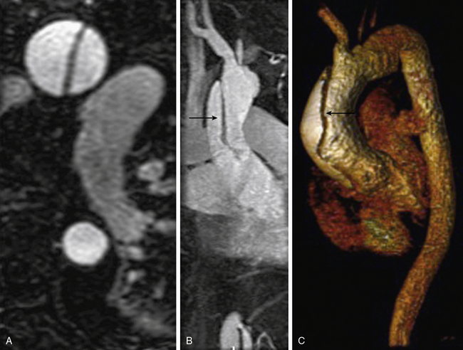
Congenital lesions are well depicted with MRA. Aortic coarctation appears as a discrete narrowing of the aorta distal to the left subclavian artery (Fig. 13-7). Magnetic resonance angiography depicts the stenosis, tortuosity of the aorta, and associated collateral vessels.21 Collateral flow assessment with MR velocity mapping can accurately evaluate the hemodynamic significance of a coarctation.22 Cine-MR imaging also permits diagnosis of a concomitant bicuspid valve and possible aortic stenosis. Magnetic resonance angiography is used after intervention to exclude complications such as stenosis or aneurysm formation.23
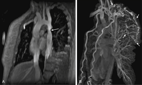
Figure 13-7 A, Oblique sagittal maximum-intensity projection (MIP) image shows aortic coarctation (arrow). B, Three-dimensional volume-rendered (3D-VR) image shows larger field of view; extensive collaterals are evident (arrows).
Magnetic resonance angiography also can distinguish between coarctation and pseudocoarctation. Pseudocoarctation is a rare asymptomatic anomaly in the descending thoracic aorta and is characterized by an elongated redundant thoracic aorta with buckling distal to the origin of the left subclavian artery. There is no pressure gradient across the buckled segment. It is regarded as a benign condition, although several reports demonstrate that complications may occur.24
Thoracic outlet syndrome
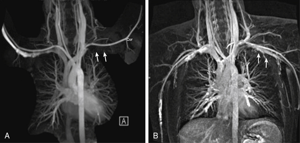
Thoracic outlet syndrome results from compression of the neurovascular bundle (subclavian artery and vein plus the brachial plexus) at the thoracic inlet. Symptoms are typically from nerve compression; the brachial plexus is involved in up to 98% of cases. Magnetic resonance imaging can demonstrate obstruction/compression of the fat surrounding the brachial plexus, and of the subclavian vein and artery. Magnetic resonance angiography is performed during abduction and adduction maneuvers of the arm to simulate physiological compression of the veins and/or arteries to confirm the diagnosis (Fig. 13-8).
Pulmonary Vessels
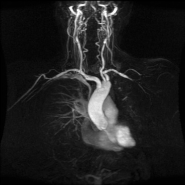
Radiofrequency ablation for atrial fibrillation has increased the role of noninvasive pulmonary vein mapping before intervention and for postprocedural surveillance for complications.25 Magnetic resonance angiography enables comprehensive planning of electrophysiological procedures with respect to number, location, and size of the pulmonary veins (Fig. 13-9). Multidetector CT is the reference standard for pulmonary embolism (PE),26 although pulmonary MRA can be performed in patients with severe allergy to iodinated contrast media (Fig. 13-10). Time-resolved MRA can be used to minimize venous contamination.27 Pulmonary artery aneurysms and stenoses can also be characterized with MRA.
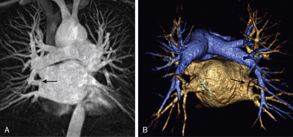
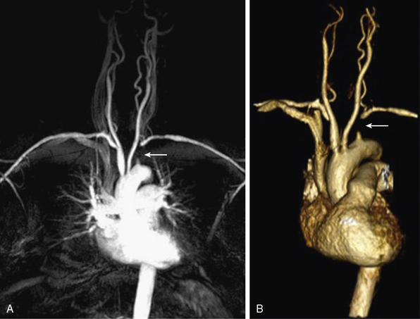
Figure 13-9 A, Coronal maximum-intensity projection (MIP) image. B, Posterior aspect of three-dimensional volume-rendered (3D-VR) image shows pulmonary arteries, left atrium and pulmonary veins, and separate opening of right middle lobe vein to left atrium (arrow).
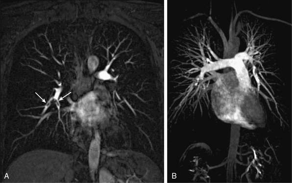
Figure 13-10 A, Coronal multiplanar reconstructed (MPR) image shows embolic filling defects in right lower lobe pulmonary artery branches (arrows). B, Coronal maximum-intensity projection (MIP) image shows whole branching pattern of pulmonary arteries but hides details. Embolic filling defects in right lower lobe pulmonary artery cannot be seen clearly.
Coronary Arteries
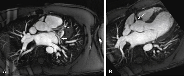
Because of its superior soft-tissue contrast, MRI provides excellent cardiac morphology and function data. The coronary arteries, however, remain elusive because of their small caliber, motion, and tortuosity (Fig. 13-11). The modality that can best image the coronary arteries noninvasively in routine clinical practice is computed tomographic angiography (CTA).28 Coronary MRA is only appropriate for coronary anomalies,29 but CT is superior for this purpose and can be performed with less than 1 mSv of radiation.
Peripheral Artery Disease of the Lower and Upper Extremities
Most peripheral artery disease (PAD) is due to atherosclerosis. Other conditions altering arterial flow to the legs include peripheral artery aneurysms, popliteal artery entrapment, cystic adventitial disease, thromboangiitis obliterans (TAO), giant cell and Takayasu’s arteritis, and (rarely) FMD.
Magnetic resonance angiography evaluation of lower-extremity PAD typically extends from the aortic bifurcation to the level of the ankle and foot (Fig. 13-12). Magnetic resonance angiography is often used to evaluate vascular anatomy in patients with PAD to plan revascularization procedures. This enables identification and characterization of all occlusive lesions, plus an evaluation of inflow and outflow vessels.
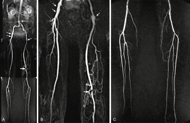
Figure 13-12 A-C, Abdominal aorta and bilateral lower-extremity runoff. Maximum-intensity projection (MIP) images show fusiform ectasia of infrarenal abdominal aorta (arrow), mild ectasia of distal external iliac artery and proximal common femoral artery (CFA) (short arrows), short-segment moderate to severe stenosis in left popliteal artery (thick arrow), and collateral vascularization. Normal three-vessel runoff is seen in each calf.
Black-blood MRA images can assess the presence of wall thickening, thrombi, intramural hematoma, atherosclerotic plaques, and penetrating atherosclerotic ulcers.30 Black-blood MRA sequences are rarely used in current runoff protocols, largely because of long acquisition times.
The standard MR runoff uses 3D CE-MRA6,31 for accurate and detailed assessment of the peripheral arteries. A recent meta-analysis of 32 studies from 1998 to 2009 shows a pooled sensitivity of 94.7% and specificity of 95.6% for diagnosing segmental steno-occlusive lesions in peripheral arteries.32 The fundamental challenge in peripheral CE-MRA is balancing accurate imaging throughout the length of the vascular tree against the imaging capabilities of the system. In general, the craniocaudal FOV requires acquisition from the juxtarenal abdominal aorta to the foot in three or four overlapping stages. In one approach, the timing of the gadolinium bolus is optimized for the superior station (abdomen and pelvis), then imaging is performed as rapidly as possible to keep up with the flow of contrast material down the distal arteries. Image quality in the first stage is excellent but often suboptimal in the third stage as gadolinium enters the venous system, with resulting venous contamination of the image. This is especially true in patients with a short arteriovenous transit time, such as those with severely ischemic limbs, where precise definition of the tibial arteries is critical. On average, contrast reaches the common femoral artery (CFA) in 24 seconds, with only an additional 5 and 7 seconds needed to reach the popliteal artery and ankle, respectively.33 Contrast travel time to the femoral arteries correlates with increasing age, male gender, history of myocardial infarction (MI), and diabetes, and is increased in the presence of aortic aneurysm. So-called moving table technology can be used to chase a single bolus of contrast agent in its distal progression.34
Goals of peripheral MRA are higher spatial resolution to better visualize smaller distal vessels, and faster scanning to lessen the negative impact of venous enhancement. Newer acquisitions and 3-tesla (3 T) scanners provide technological advances. Parallel imaging with multichannel phased-array coils are used to reduce imaging time.35 Full-length dedicated peripheral multichannel vascular surface coils improve signal. Time-resolved acquisitions can be used in standard protocols and may be particularly useful in the calves. To reduce venous contamination, subsystolic midfemoral venous compression can be applied.36
Hybrid injection protocols overcome some technical limitations and are more accurate for evaluating the popliteal trifurcation and foot vessels.37,38 Initial precontrast low-resolution axial 2D TOF sequences are obtained to optimize prescription of the 3D slabs. The first injection is used to acquire high–spatial resolution MRA of the calf and foot to minimize venous contamination; 3D time-resolved MRA for this stage can eliminate the need for bolus timing and decrease the total contrast load. The second injection is used for acquisition of both the aortoiliac and femoral station. Complementary TOF sequences are used to assess the ankle and foot. A typical dose is 0.2 mmol/kg of gadolinium-based contrast administered at a flow rate of 1.5 to 2 mL/sec, followed by 20 mL of saline. Accurate synchronization of the peak contrast material in the vascular bed and central k-space acquisition is essential for high image quality. Timing can include a test bolus or bolus tracking. For patients with asymmetrical flow to the legs, optimal arterial opacification in the more symptomatic leg (i.e., slower flow) can be challenging. Time-resolved sequences can determine peak arterial and venous enhancement of both legs so timing can be adjusted for the more symptomatic leg.31
Magnetic resonance angiography can also be used to evaluate patients after endovascular intervention.39 Following bypass surgery, CE-MRA can evaluate graft location, patency, and stenosis of the proximal and distal anastomosis, even for small distal grafts. However, magnetic susceptibility created by metallic clips is problematic even when source images are used for the evaluation.
Blood pool contrast agents show promise to decrease gadolinium doses and provide a much longer time window for data acquisition, based on prolonged relaxivity in comparison to conventional gadolinium agents.40 Venous contamination and SNR loss from less pronounced T1 shortening are some challenges in blood pool MRA.31 Newer noncontrast MRA techniques that use acquisitions in systole and diastole to produce contrast41 are promising for runoff exams in patients with impaired renal function. Dedicated evaluation of the pedal arteries (Fig. 13-13) is comparable to selective DSA.42
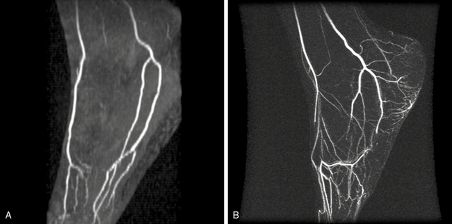
Figure 13-13 A, Time of flight (TOF) image of normal pedal arteries. B, Contrast-enhanced magnetic resonance angiography (CE-MRA) maximum intensity projection (MIP) reconstruction of pedal arteries in patient with cryoglobulinemia and small-vessel vasculitis. Arteries of pedal arch are occluded. Moderate venous enhancement is present.
Magnetic resonance angiography is used to evaluate patients with clinically suspected popliteal artery entrapment syndrome (Fig. 13-14) and cystic adventitial disease. Popliteal artery entrapment is an uncommon peripheral arterial disorder resulting from an anomalous relationship between the popliteal artery and the medial head of the gastrocnemius muscle. Magnetic resonance imaging defines the anatomical relationships, and MRA allows accurate evaluation of vascular compromise during provocative plantar flexion and at rest.43,44 Cystic adventitial disease accounts for 1 in 1200 cases of calf claudication. A mucin-containing cyst in the popliteal artery wall compromises arterial flow and causes claudication. Water signal makes the cyst appear hyperintense on T2-weighted images, and MRA reveals popliteal artery stenosis.43,45
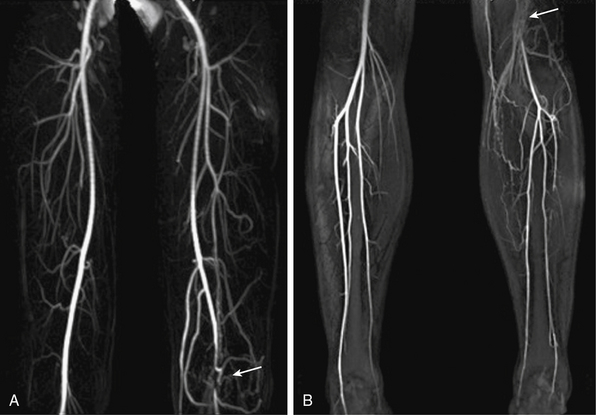
Figure 13-14 A-B, Arterial-phase maximum-intensity projection (MIP) images of leg show left popliteal artery entrapment (arrows).
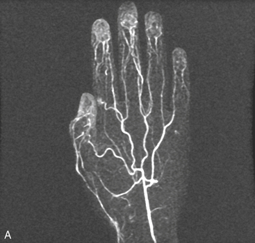
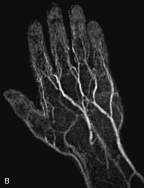
Upper-extremity vascular disease affecting the subclavian artery includes stenosis, aneurysm, or compression due to thoracic outlet syndrome. Imaging of the forearm and hand may be indicated to evaluate vasculitis or ischemia secondary to trauma (Fig. 13-15). The spatial resolution of MRA is inferior to DSA, although it is useful as a noninvasive technique.46 The acquisition window is restricted to the few seconds between full enhancement of the arteries and the beginning of venous contamination. Blood pressure cuff inflation proximal to the imaged area can extend imaging time and enhance image quality of the palmar, metacarpal, and digital arteries.47
Abdominal Vessels
Both CT and MR provide excellent imaging of the abdominal aorta and its branches. Magnetic resonance angiography is indicated to evaluate renal artery stenosis (RAS), mesenteric artery disease, and abdominal aortic aneurysm (AAA), dissection, or occlusion. Single breath-hold CE-MRA permits high contrast between vessels and surrounding organs. Technical advances such as time-resolved and parallel imaging can be incorporated into clinical protocols. For detailed spatial measurements, black-blood (e.g., DIR) images are optimal for measurement of the lumen and vessel diameter and assessment of the aorta wall. Volumetric mask imaging will ensure that the 3D volume is appropriately placed. After contrast injection, at least two data sets (arterial and delayed phase) are acquired. This strategy does not significantly prolong the study and can provide valuable information, especially regarding venous structures. It can also be very useful for slow flow in large aneurysms, or imaging a false lumen where the initial acquisition does not provide adequate enhancement. Contrast doses of 20 mL, administered at 2 mL/s, are usually sufficient.
Renal artery imaging
The most common cause of RAS is atherosclerosis, which often involves the ostia or proximal 1 to 2 cm of the renal arteries. Fibromuscular dysplasia is the second most common cause of RAS and typically affects the distal two thirds of the main renal artery.
Contrast-enhanced MR is the modality of choice for patients with hypertension and clinically suspected RAS.48 Coronal imaging is prescribed to minimize acquisition time (i.e., fewer phase-encoding steps). Parallel imaging can be used to minimize craniocaudal motion in the distal renal arteries.49 The advantage of MRA over CT is that dense calcification causes CT artifacts that obscure the lumen and cause overestimation of stenosis severity. Calcium deposits accumulate at or near the ostium where stenosis detection is critical. Three-dimensional CE-MRA with subtracted MIPs has less artifact at the ostium, and PC techniques can add information regarding hemodynamic significance. Secondary findings such as poststenotic dilation and delayed renal parenchymal enhancement are also important.
Magnetic resonance angiography can be used for clinically suspected FMD, but the presence of alternating webs and dilation may not be captured by the spatial resolution of MRA, particularly in the distal renal arteries. Thus, a negative MRA cannot entirely exclude the diagnosis.
Abdominal aorta imaging
Abdominal aortic aneurysms associated with atherosclerosis are typically fusiform; a saccular configuration should raise the possibility of a mycotic aneurysm. Aneurysm evaluation includes the proximal and distal extent of the aneurysm, as well as its relationship to visceral branch vessels. Three-dimensional MRA can identify the main and any supernumerary renal arteries (Fig. 13-16) and mesenteric arteries.
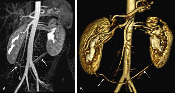
Figure 13-16 A, Coronal maximum-intensity projection (MIP) image. B, Three-dimensional volume-rendered (3D-VR) images show bilateral accessory inferior renal artery originating from left common iliac artery (CIA) (arrows).
Multidetector CT is the preferred modality for planning endovascular repair of AAAs and surveillance of stent grafts. Magnetic resonance angiography does not image calcification.50 Magnetic resonance angiography is safe for nonferromagnetic stents and does not induce heating or stent deflection.51,52
Susceptibility artifact from stents limit postprocedural studies. However, nitinol and PTFE devices have minimal MR artifact, and early data suggest that MRA can be used in patients with nitinol grafts.53 Contrast-enhanced MRA is also accurate in the depiction of endoleaks. Time-resolved MRA is also an attractive method to characterize endoleaks because contrast passage into the aneurysm sac can be visualized as a cine loop.54
Abdominal aortic dissection
Magnetic resonance angiography is used to detect propagation of aortic dissection into the abdominal aorta. It can identify the proximal and distal flap as well as involvement of the visceral branches. The celiac trunk and SMA usually arise from the true lumen, but extension of the flap into the celiac trunk, thrombosis of the false lumen, or compression of the true lumen can lead to hepatic or splenic infarcts. Magnetic resonance angiography reliably depicts the true and false lumen. For 3D acquisitions, postprocessing enables selective viewing of branch vessels. Delayed imaging can be used to characterize slow flow into the false lumen.
Aortic occlusion
Distal aortic occlusion is most commonly due to thromboembolic disease. Thrombus may be superimposed on severe atherosclerosis of the distal aorta and common iliac arteries. Magnetic resonance angiography is used to evaluate not only the occlusion but also the collateral circulation and distal reconstitution.
Mesenteric arteries
Chronic mesenteric ischemia (CMI) is most commonly a consequence of atherosclerosis in the proximal visceral arteries, but can also be a sequela to dissection, median arcuate ligament syndrome (Fig. 13-17), visceral artery dissection, vasculitides, and connective tissue disorders.
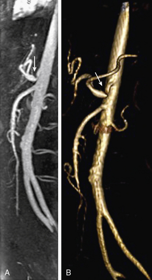
Figure 13-17 Median arcuate ligament syndrome.
A, Sagittal maximum-intensity projection (MIP). B, Three-dimensional volume-rendered (3D-VR) images obtained from arterial phase of contrast-enhanced magnetic resonance angiography (CE-MRA) show stenosis due to median arcuate ligament compression in origin of celiac trunk (arrow).
Most patients do not develop symptoms of CMI unless two of the three mesenteric arteries are occluded. Magnetic resonance angiography is highly accurate for evaluating mesenteric origins, where the majority of stenoses develop (Fig. 13-18). High accuracy is maintained to the level of second-order branches. Qualitative and quantitative flow measurements with cine–phase contrast MRI from the SMA and vein can be performed.55
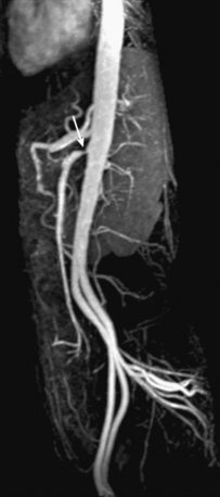
Figure 13-18 Sagittal maximum-intensity projection (MIP) image shows severe stenosis of superior mesenteric artery (SMA) (arrow).
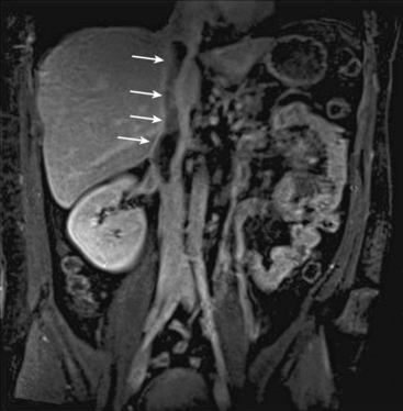
Patients who present with severe abdominal pain and clinical suspicion for acute mesenteric ischemia require urgent imaging because of the risk of irreversible bowel damage. Major causes of acute mesenteric ischemia are SMA emboli (30%-50%), SMA thrombosis (15%-30%), acute mesenteric vein thrombosis (5%-10%), and nonocclusive mesenteric vasoconstriction (20%-30%).56 Multidetector CT is typically used for initial imaging, since it has more widespread availability, less motion artifact in patients who are acutely ill, and the risk of bowel ischemia/infarction outweighs potential concerns for iodine-induced nephrotoxicity. However, in patients who do not require immediate intervention, MRA can be used for follow-up to characterize chronic atherosclerosis, mesenteric occlusion, aneurysm formation, and vasculitis. Characteristics of vasculitis include findings of wall thickening and increased gadolinium enhancement (Fig. 13-19).
Transplantation
Magnetic resonance angiography is used in pre- and postoperative transplant patients. Detailed knowledge of vascular anatomy is essential to ensure safe and successful transplantation surgery. Magnetic resonance angiography is used in presurgical evaluation of the recipient and living donors57,58 and in follow-up of patients after transplantation of the liver, kidney (Fig. 13-20), or pancreas, particularly in cases of suspected vascular complications.
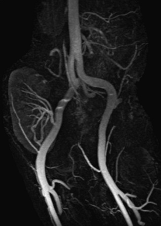
Figure 13-20 Oblique coronal maximum-intensity projection (MIP) reconstruction shows patency of renal artery anastomosis of transplanted kidney.
In living donor liver transplantation, MRA provides a complete evaluation of the hepatic vascular anatomy in the presurgical phase. It provides information regarding biliary anatomy and assessment of hepatic parenchyma for diffuse and focal abnormalities.59 Magnetic resonance angiography has high sensitivity and excellent negative predictive value for detection of clinically significant vascular stenosis in liver transplantation.60
After renal transplantation, MRA can be used for suspected vascular complications to identify patients who would benefit from angioplasty.61 In pancreas transplantation, MRA identifies arterial and venous complications.62 Accurate maps of rectus and gluteal muscle perforator arteries can also be obtained for preoperative planning of breast reconstruction.63
Inflammatory Diseases of the Arterial Wall
Magnetic resonance imaging is the primary technology for diagnosis and follow-up of patients with large vessel vasculitis, based on identification of vessel wall edema and thickening that can be seen before lumen changes. Black-blood DIR imaging is preferred for wall morphology, and postcontrast imaging can be used to demonstrate mural enhancement. Other wall abnormalities seen in vasculitis include ulceration, dissection, stenosis, occlusion, and aneurysm.
Takayasu’s arteritis is an inflammatory disease that typically affects young women, and early diagnosis can be difficult because of its nonspecific symptoms and serological markers. Diagnosis and identification of disease activity with MRA is important to guide adequate therapy because severe stenoses, occlusion, or aneurysm are late irreversible manifestations. MRA findings suggestive of Takayasu’s arteritis include stenoses of the aorta and its major branches (Fig. 13-21). Involvement of the pulmonary arteries is seen in 70% of patients and increases diagnostic confidence.64 Biomarkers are less reliable, whereas MRA shows early changes and evaluates disease activity. Findings include arterial wall thickening and enhancement in the active phase, mural thrombi, fusiform vascular dilations, and multifocal stenosis, and then thickened aortic valvular cusps in the chronic phase.65
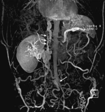
Figure 13-21 Coronal maximum-intensity projection (MIP) image shows occlusion of distal abdominal aorta in region of bifurcation (arrow), intrahepatic inferior vena cava (IVC) thrombosis (short arrows), and occlusion of bilateral common iliac vein, with extensive lumbar, epigastric, and azygos collateral veins in same patient.
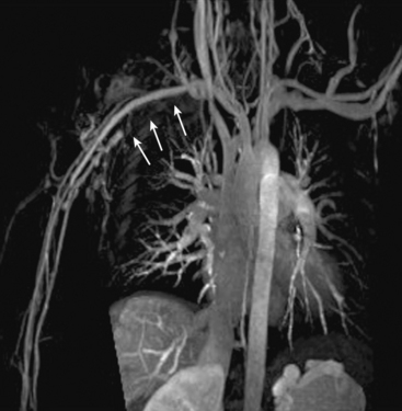
Giant cell arteritis (GCA) is a large-vessel inflammatory disease affecting primarily older patients. Magnetic resonance angiography is used to diagnose associated thoracic aortic aneurysms and evaluates involvement of large peripheral arteries such as the subclavian arteries (Fig. 13-22).
Magnetic Resonance Venography
Magnetic resonance venography (MRV) protocols differ from arterial imaging because of the differences in flow and disease patterns. As with arterial studies, noncontrast MRI such as TOF has been largely replaced with CE-MRV, even though 2D TOF can cover large volumes and detect slow flow.
The problems of flow-based techniques and the relatively long acquisition times are overcome by the rapid 3D sequences used for arteriography. Subtraction data sets can limit signal from arteries to produce high-quality venograms.66
Thrombus has relatively high T1 signal from the formation of methemoglobin. Blood products have characteristic MR signal changes that are used in the evaluation of very early to late hemorrhage.67 Inflammatory changes from acute deep vein thrombosis (DVT) are characteristic. After contrast enhancement, mural enhancement of the vessel wall is seen around an acutely thrombosed vein, appearing as a bull’s eye. In conjunction with the inflammatory changes and organization of the thrombus, this finding helps differentiate acute from chronic thrombosis.
Deep Vein Thrombosis
When the vein in question can be accessed by sonography, ultrasound is the first-line modality for DVT. Magnetic resonance venography is a second-line modality and used when ultrasound is limited by patient body habitus, limited acoustic window, or for other reasons. Gadolinium is typically used, and 3D sequences routinely identify filling defects diagnostic for DVT (Fig. 13-23). There is no role for DSA in diagnosis, although percutaneous access can be used for therapy. Computed tomography venography can also be performed. Many early studies have established 2D TOF accuracy for thrombosis68,69 in the large central veins, although contrast is beneficial for better characterization of more superficial and perforating veins with slow flow and retrograde flow.70 Newer noncontrast MRA techniques have been used for DVT, but their utility requires more comprehensive studies. Magnetic resonance venography is also useful for patients with suspected renal vein thrombosis and can show enhancement of tumor thrombus.71 Delayed-phase MRA also provides an evaluation of the inferior vena cava (IVC) and hepatic and portal veins.
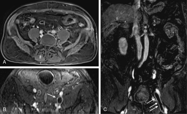
Figure 13-23 Axial (A-B) and coronal (C) postcontrast venous phase images show left common iliac, external iliac, and common femoral vein thromboses (arrows).
Occlusive diseases of central thoracic veins (Fig. 13-24) are commonly seen in patients with malignancy or coagulopathy or long-term use of central venous catheters for hemodialysis, hyperalimentation, or chemotherapy. Magnetic resonance venography is very helpful for vascular mapping in patients who have chronic venous occlusion but require central venous catheter placement. Magnetic resonance venography is the best modality for compression and occlusion of the abdomen and pelvis. The IVC (Fig. 13-25) and iliac veins, lymph nodes, tumors, and large organs can be identified. Finally, MRV delineates congenital venous anomalies and can be used to assess patency.
Vessel Wall Imaging
Sudden catastrophic adverse events such as stroke, MI, and limb ischemia do not necessarily correlate with lumen stenosis and may be better predicted by plaque characterization. Thus, vessel wall imaging will become a critical component of a comprehensive vascular study. Moreover, because of the multicontrast capabilities, MRI is well poised for wall component imaging, including the separation of wall layers72 and imaging the lipid necrotic core and fibrous matrix. Noncontrast techniques have achieved spatial resolution to image segments of an arterial tree,41 and contrast enhancement over time can quantify the size of the lipid necrotic core and evaluate plaque inflammation.73 Sophisticated contrast agents, such as ultra-small superparamagnetic iron oxides that accumulate in predominantly ruptured or rupture prone atherosclerotic plaques, can potentially identify high-risk lesions.74 Novel implantable contrast agents75 may enable more accurate vessel wall planimetry for longitudinal studies of vessel walls. Delayed and dynamic contrast-enhanced studies have been used to study plaque neovascularization.76 Finally, evaluation of wall-thickness changes in lower-extremity peripheral vein bypass grafts has been demonstrated.72,77
1 Ho V.B., Corse W.R. MR angiography of the abdominal aorta and peripheral vessels. Radiol Clin North Am. 2003;41:115–144.
2 Levy R.A., Prince M.R. Arterial-phase three-dimensional contrast-enhanced MR angiography of the carotid arteries. AJR Am J Roentgenol. 1996;167:211–215.
3 Vogt F.M., Goyen M., Debatin J.F. MR angiography of the chest. Radiol Clin North Am. 2003;41:29–41.
4 Toussaint J.F., LaMuraglia G.M., Southern J.F., et al. Magnetic resonance images lipid, fibrous, calcified, hemorrhagic, and thrombotic components of human atherosclerosis in vivo. Circulation. 1996;94:932–938.
5 Yucel E.K., Anderson C.M., Edelman R.R., et al. AHA scientific statement. Magnetic resonance angiography: update on applications for extracranial arteries. Circulation. 1999;100:2284–2301.
6 Prince M.R., Yucel E.K., Kaufman J.A., et al. Dynamic gadolinium-enhanced three-dimensional abdominal MR arteriography. J Magn Reson Imaging. 1993;3:877–881.
7 Prince M.R. Gadolinium-enhanced MR aortography. Radiology. 1994;191:155–164.
8 Kroencke T.J., Wasser M.N., Pattynama P.M., et al. Gadobenate dimeglumine-enhanced MR angiography of the abdominal aorta and renal arteries. AJR Am J Roentgenol. 2002;179:1573–1582.
9 Cowper S.E., Robin H.S., Steinberg S.M., et al. Scleromyxoedema-like cutaneous diseases in renal-dialysis patients. Lancet. 2000;356:1000–1001.
10 Sadowski E.A., Bennett L.K., Chan M.R., et al. Nephrogenic systemic fibrosis: risk factors and incidence estimation. Radiology. 2007;243:148–157.
11 Ersoy H., Rybicki F.J. Biochemical safety profiles of gadolinium-based extracellular contrast agents and nephrogenic systemic fibrosis. J Magn Reson Imaging. 2007;26:1190–1197.
12 Cavagna E., Berletti R., Schiavon F. In vivo evaluation of intravascular stents at three-dimensional MR angiography. Eur Radiol. 2001;11:2531–2535.
13 Wardlaw J.M., Chappell F.M., Best J.J., et al. Non-invasive imaging compared with intra-arterial angiography in the diagnosis of symptomatic carotid stenosis: a meta-analysis. Lancet. 2006;367:1503–1512.
14 Randoux B., Marro B., Koskas F., et al. Proximal great vessels of aortic arch: comparison of three-dimensional gadolinium-enhanced MR angiography and digital subtraction angiography. Radiology. 2003;229:697–702.
15 Moore A.G., Eagle K.A., Bruckman D., et al. Choice of computed tomography, transesophageal echocardiography, magnetic resonance imaging, and aortography in acute aortic dissection: International Registry of Acute Aortic Dissection (IRAD). Am J Cardiol. 2002;89:1235–1238.
16 Buckley O., Rybicki F.J., Gerson D.S., et al. Imaging features of intramural hematoma of the aorta. Int J Cardiovasc Imaging. 2010;26:65–76.
17 Hayashi H., Matsuoka Y., Sakamoto I., et al. Penetrating atherosclerotic ulcer of the aorta: imaging features and disease concept. Radiographics. 2000;20:995–1005.
18 Lohan D.G., Krishnam M., Tomasian A., et al. Time-resolved MR angiography of the thorax. Magn Reson Imaging Clin N Am. 2008;16:235–248. viii
19 Krishnam M.S., Tomasian A., Malik S., et al. Image quality and diagnostic accuracy of unenhanced SSFP MR angiography compared with conventional contrast-enhanced MR angiography for the assessment of thoracic aortic diseases. Eur Radiol. 2010;20:1311–1320.
20 Cosottini M., Zampa V., Petruzzi P., et al. Contrast-enhanced three-dimensional MR angiography in the assessment of subclavian artery diseases. Eur Radiol. 2000;10:1737–1744.
21 Godart F., Labrot G., Devos P., et al. Coarctation of the aorta: comparison of aortic dimensions between conventional MR imaging, 3D MR angiography, and conventional angiography. Eur Radiol. 2002;12:2034–2039.
22 Holmqvist C., Stahlberg F., Hanseus K., et al. Collateral flow in coarctation of the aorta with magnetic resonance velocity mapping: correlation to morphological imaging of collateral vessels. J Magn Reson Imaging. 2002;15:39–46.
23 Bogaert J., Kuzo R., Dymarkowski S., et al. Follow-up of patients with previous treatment for coarctation of the thoracic aorta: comparison between contrast-enhanced MR angiography and fast spin-echo MR imaging. Eur Radiol. 2000;10:1847–1854.
24 Taneja K., Kawlra S., Sharma S., et al. Pseudocoarctation of the aorta: complementary findings on plain film radiography, CT, DSA, and MRA. Cardiovasc Intervent Radiol. 1998;21:439–441.
25 Kato R., Lickfett L., Meininger G., Dickfeld T., et al. Pulmonary vein anatomy in patients undergoing catheter ablation of atrial fibrillation: lessons learned by use of magnetic resonance imaging. Circulation. 2003;107:2004–2010.
26 Hunsaker A.R., Lu M.T., Goldhaber S.Z., et al. Imaging in acute pulmonary embolism with special clinical scenarios. Circ Cardiovasc Imaging. 2010;3:491–500.
27 Ersoy H., Goldhaber S.Z., Cai T., et al. Time-resolved MR angiography: a primary screening examination of patients with suspected pulmonary embolism and contraindications to administration of iodinated contrast material. AJR Am J Roentgenol. 2007;188:1246–1254.
28 Otero H.J., Steigner M.L., Rybicki F.J. The "post-64" era of coronary CT angiography: understanding new technology from physical principles. Radiol Clin North Am. 2009;47:79–90.
29 Gharib A.M., Ho V.B., Rosing D.R., et al. Coronary artery anomalies and variants: technical feasibility of assessment with coronary MR angiography at 3T. Radiology. 2008;247:220–227.
30 Tatli S., Lipton M.J., Davison B.D., et al. From the RSNA refresher courses: MR imaging of aortic and peripheral vascular disease. Radiographics. 2003;23:S59–S78. Spec No
31 Ersoy H., Rybicki F.J. MR angiography of the lower extremities. AJR Am J Roentgenol. 2008;190:1675–1684.
32 Menke J., Larsen J. Meta-analysis: accuracy of contrast-enhanced magnetic resonance angiography for assessing steno-occlusions in peripheral arterial disease. Ann Intern Med. 2010;153:325–334.
33 Prince M.R., Chabra S.G., Watts R., et al. Contrast material travel times in patients undergoing peripheral MR angiography. Radiology. 2002;224:55–61.
34 Meaney J.F., Ridgway J.P., Chakraverty S., et al. Stepping-table gadolinium-enhanced digital subtraction MR angiography of the aorta and lower extremity arteries: preliminary experience. Radiology. 1999;211:59–67.
35 Maki J.H., Wilson G.J., Eubank W.B., et al. Utilizing SENSE to achieve lower station sub-millimeter isotropic resolution and minimal venous enhancement in peripheral MR angiography. J Magn Reson Imaging. 2002;15:484–491.
36 Zhang H.L., Ho B.Y., Chao M., et al. Decreased venous contamination on 3D gadolinium-enhanced bolus chase peripheral MR angiography using thigh compression. AJR Am J Roentgenol. 2004;183:1041–1047.
37 von Kalle T., Gerlach A., Hatopp A., et al. Contrast-enhanced MR angiography (CEMRA) in peripheral arterial occlusive disease (PAOD): conventional moving table technique versus hybrid technique. Rofo. 2004;176:62–69.
38 Tongdee R., Narra V.R., McNeal G., et al. Hybrid peripheral 3D contrast-enhanced MR angiography of calf and foot vasculature. AJR Am J Roentgenol. 2006;186:1746–1753.
39 Rybicki F.J., Nallamshetty L., Yucel E.K., et al. ACR appropriateness criteria on recurrent symptoms following lower-extremity angioplasty. J Am Coll Radiol. 2008;5:1176–1180.
40 Nikolaou K., Kramer H., Grosse C., et al. High-spatial-resolution multistation MR angiography with parallel imaging and blood pool contrast agent: Initial experience. Radiology. 2006;241:861–872.
41 Miyazaki M., Lee V.S. Nonenhanced MR angiography. Radiology. 2008;248:20–43.
42 Kreitner K.F., Kunz R.P., Herber S., et al. MR angiography of the pedal arteries with gadobenate dimeglumine, a contrast agent with increased relaxivity, and comparison with selective intraarterial DSA. J Magn Reson Imaging. 2008;27:78–85.
43 Elias D.A., White L.M., Rubenstein J.D., et al. Clinical evaluation and MR imaging features of popliteal artery entrapment and cystic adventitial disease. AJR Am J Roentgenol. 2003;180:627–632.
44 Atilla S., Ilgit E.T., Akpek S., et al. MR imaging and MR angiography in popliteal artery entrapment syndrome. Eur Radiol. 1998;8:1025–1029.
45 Crolla R.M., Steyling J.F., Hennipman A., et al. A case of cystic adventitial disease of the popliteal artery demonstrated by magnetic resonance imaging. J Vasc Surg. 1993;18:1052–1055.
46 Krause U., Pabst T., Kenn W., et al. High resolution contrast enhanced MR-angiography of the hand arteries: preliminary experiences. Vasa. 2002;31:179–184.
47 Wentz K.U., Frohlich J.M., von Weymarn C., et al. High-resolution magnetic resonance angiography of hands with timed arterial compression (tac-MRA). Lancet. 2003;361:49–50.
48 Vasbinder G.B., Nelemans P.J., Kessels A.G., et al. Diagnostic tests for renal artery stenosis in patients suspected of having renovascular hypertension: a meta-analysis. Ann Intern Med. 2001;135:401–411.
49 Vasbinder G.B., Maki J.H., Nijenhuis R.J., et al. Motion of the distal renal artery during three-dimensional contrast-enhanced breath-hold MRA. J Magn Reson Imaging. 2002;16:685–696.
50 Lutz A.M., Willmann J.K., Pfammatter T., et al. Evaluation of aortoiliac aneurysm before endovascular repair: comparison of contrast-enhanced magnetic resonance angiography with multidetector row computed tomographic angiography with an automated analysis software tool. J Vasc Surg. 2003;37:619–627.
51 Shellock F.G., Shellock V.J. Metallic stents: evaluation of MR imaging safety. AJR Am J Roentgenol. 1999;173:543–547.
52 Engellau L., Olsrud J., Brockstedt S., et al. MR evaluation ex vivo and in vivo of a covered stent-graft for abdominal aortic aneurysms: ferromagnetism, heating, artifacts, and velocity mapping. J Magn Reson Imaging. 2000;12:112–121.
53 Cejna M., Loewe C., Schoder M., et al. MR angiography vs CT angiography in the follow-up of nitinol stent grafts in endoluminally treated aortic aneurysms. Eur Radiol. 2002;12:2443–2450.
54 Stavropoulos S.W., Charagundla S.R. Imaging techniques for detection and management of endoleaks after endovascular aortic aneurysm repair. Radiology. 2007;243:641–655.
55 Ersoy H. The role of noninvasive vascular imaging in splanchnic and mesenteric pathology. Clin Gastroenterol Hepatol. 2009;7:270–278.
56 Fleischmann D. Multiple detector-row CT angiography of the renal and mesenteric vessels. Eur J Radiol. 2003;45(Suppl 1):S79–S87.
57 Vosshenrich R., Fischer U. Contrast-enhanced MR angiography of abdominal vessels: is there still a role for angiography? Eur Radiol. 2002;12:218–230.
58 Laissy J.P., Trillaud H., Douek P. MR angiography: noninvasive vascular imaging of the abdomen. Abdom Imaging. 2002;27:488–506.
59 Sahani D., Mehta A., Blake M., et al. Preoperative hepatic vascular evaluation with CT and MR angiography: implications for surgery. Radiographics. 2004;24:1367–1380.
60 Kim B.S., Kim T.K., Jung D.J., et al. Vascular complications after living related liver transplantation: evaluation with gadolinium-enhanced three-dimensional MR angiography. AJR Am J Roentgenol. 2003;181:467–474.
61 Hohenwalter M.D., Skowlund C.J., Erickson S.J., et al. Renal transplant evaluation with MR angiography and MR imaging. Radiographics. 2001;21:1505–1517.
62 Hagspiel K.D., Nandalur K., Pruett T.L., et al. Evaluation of vascular complications of pancreas transplantation with high-spatial-resolution contrast-enhanced MR angiography. Radiology. 2007;242:590–599.
63 Newman T.M., Vasile J., Levine J.L., et al. Perforator flap magnetic resonance angiography for reconstructive breast surgery: a review of 25 deep inferior epigastric and gluteal perforator artery flap patients. J Magn Reson Imaging. 2010;31:1176–1184.
64 Yamada I., Nakagawa T., Himeno Y., et al. Takayasu arteritis: diagnosis with breath-hold contrast-enhanced three-dimensional MR angiography. J Magn Reson Imaging. 2000;11:481–487.
65 Choe Y.H., Han B.K., Koh E.M., et al. Takayasu’s arteritis: assessment of disease activity with contrast-enhanced MR imaging. AJR Am J Roentgenol. 2000;175:505–511.
66 Lebowitz J.A., Rofsky N.M., Krinsky G.A., et al. Gadolinium-enhanced body MR venography with subtraction technique. AJR Am J Roentgenol. 1997;169:755–758.
67 Bradley W.G.Jr. MR appearance of hemorrhage in the brain. Radiology. 1993;189:15–26.
68 Spritzer C.E., Arata M.A., Freed K.S. Isolated pelvic deep venous thrombosis: relative frequency as detected with MR imaging. Radiology. 2001;219:521–525.
69 Carpenter J.P., Holland G.A., Baum R.A., et al. Magnetic resonance venography for the detection of deep venous thrombosis: comparison with contrast venography and duplex Doppler ultrasonography. J Vasc Surg. 1993;18:734–741.
70 Ruehm S.G., Zimny K., Debatin J.F. Direct contrast-enhanced 3D MR venography. Eur Radiol. 2001;11:102–112.
71 Laissy J.P., Menegazzo D., Debray M.P., et al. Renal carcinoma: diagnosis of venous invasion with Gd-enhanced MR venography. Eur Radiol. 2000;10:1138–1143.
72 Mitsouras D., Owens C.D., Conte M.S., et al. In vivo differentiation of two vessel wall layers in lower extremity peripheral vein bypass grafts: application of high-resolution inner-volume black blood 3D FSE. Magn Reson Med. 2009;62:607–615.
73 Saam T., Hatsukami T.S., Takaya N., et al. The vulnerable, or high-risk, atherosclerotic plaque: noninvasive MR imaging for characterization and assessment. Radiology. 2007;244:64–77.
74 Kooi M.E., Cappendijk V.C., Cleutjens K.B., et al. Accumulation of ultrasmall superparamagnetic particles of iron oxide in human atherosclerotic plaques can be detected by in vivo magnetic resonance imaging. Circulation. 2003;107:2453–2458.
75 Mitsouras D., Vemula P.K., Yu P., et al. Immobilized contrast-enhanced MRI: gadolinium-based long-term MR contrast enhancement of the vein graft vessel wall. Magn Reson Med. 2010.
76 Calcagno C., Mani V., Ramachandran S., et al. Dynamic contrast enhanced (DCE) magnetic resonance imaging (MRI) of atherosclerotic plaque angiogenesis. Angiogenesis. 2010;13:87–99.
77 Rybicki F.J., Mitsouras D., Owens C.D., et al. Lower-extremity peripheral vein bypass graft wall thickness changes demonstrated at 1 and 6 months after surgery with ultra-high spatial resolution black blood inner volume three-dimensional fast spin echo magnetic resonance imaging. Int J Cardiovasc Imaging. 2008;24:529–533.