12 PACEMAKER ASSESSMENT
The electrical stimulus which causes the heart to contract originates in the sinoatrial (SA) node in the right atrium. This incites the two atria to contract via a conduction pathway. The impulse also passes from the SA node to the atrioventricular (AV) node and thence along the bundle of His to the right and left ventricles (Fig. 12.1).
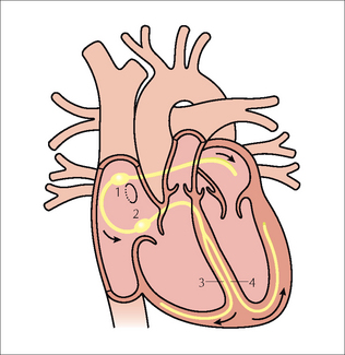
Figure 12.1 Conducting system of the heart:1 = SA node; 2 = AV node;3 = right bundle branch;4 = left bundle branch. The position of the foramen ovale is shown as a ring inferior to the SA node. Note the additional electrical pathway also originating in the SA node. This carries electrical impulses to the right and left atria.
Various pathological conditions can affect these conduction pathways and cause dysrhythmias or heart block when this electrical system fails to conduct properly. Heart block can be managed by placing a permanent pacemaker within the heart. Some pacemakers have a lead which is positioned in the right ventricle. Others position a lead in the right atrium as well as in the right ventricle. In addition there are devices which resemble pacemakers which can treat some fast life-threatening dysrhythmias by means of pacing control or by defibrillation. These devices are known as implantable converter defibrillators (ICDs).
In an ideal world we would pace the left side of the heart, but the arterial pressure is high and this would cause haemostatic problems. Consequently, the low pressure right side of the heart is utilised.
PACEMAKER UNITS1–4
A permanent pacemaker has two components. The first is a power source. This is a pulse generator which contains semiconductor chips and a sealed lithium battery. It has a working life of approximately 10 years. The second component is a flexible lead (or leads). These are insulated wires which conduct the pulse to the metal electrodes positioned against the cardiac muscle.
The pacemaker lead is introduced via a cut down on a subclavian vein. The generator is placed in a chest wall pocket fashioned under the skin.
SINGLE CHAMBER : DUAL CHAMBER PACEMAKERS1–4
A single chamber pacemaker (i.e. one lead only) may be used to manage an atrial or a ventricular dysrhythmia. For atrial dysrhythmias—the electrode is positioned in the right atrial appendage. For a ventricular dysrhythmia—the electrode is placed against the myocardium at the apex of the right ventricle. Single chamber ventricular pacing is the most basic. It is activated when the ventricular rate falls too low, and only paces the ventricles. The activity of the atria is ignored. Nowadays these single lead systems are being inserted much less frequently.
A dual chamber pacemaker (i.e. two leads) attempts to synchronise the atrial and ventricular systems, since this is much more physiological. One electrode is positioned in the right atrium and the other electrode is placed at the apex of the right ventricle.
Some pacemakers have three electrodes: one in the right atrium, a second in the right ventricle, and a third lead is placed in the coronary sinus (Fig. 12.2). The coronary sinus lead paces the left ventricle. This system is referred to as biventricular pacing.
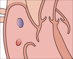
Figure 12.2 The position of the coronary sinus opening (red) into the right atrium. The sinus is approximately 3 cm long and runs in the AV groove on the posterior border of the heart. The coronary sinus is the vessel which transmits most of the venous drainage of the myocardium. The site of the foramen ovale is shown in blue.
ICDs are used to manage specific ventricular dysrhythmias. These devices have a single lead and the majority of them have a radiographic appearance which is similar to that of a single chamber pacemaker.
POST-IMPLANTATION CXRS1–7
Why obtain a CXR? It is obtained in order to make sure that all is well. A clinically unsuspected complication from pacemaker insertion is infrequent. Nevertheless, complications do occur.
CXR practice varies between hospitals and clinics. Most physicians obtain a frontal CXR soon after insertion of the pacemaker. Others obtain lateral and frontal radiographs. If an atrial electrode is utilised then a lateral CXR is usually needed so as to ensure that the tip of the electrode (sited in the right atrial appendage) points towards the anterior wall of the thorax.
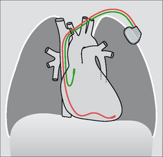
Figure 12.5 Optimal electrode positions. Dual chamber pacemaker. Pacemakers tend to be introduced from the left side in right-handed patients.
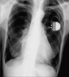
Figure 12.7 Optimal electrode position. Single chamber pacemaker. The ventricular lead has its tip situated at the apex of the right ventricle. (Retouched.)
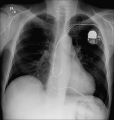
Figure 12.8 Optimal electrode positions. Dual chamber pacemaker. The atrial lead has its tip in the right atrium; the ventricular lead has its tip at the apex of the right ventricle. (Retouched.)
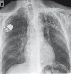
Figure 12.9 Abandoned left subclavian lead. Pacemaker electrodes usually become adherent to the myocardium within a few weeks of implantation7. Some leads adhere to a vein or to the wall of the right atrium. When a pacemaker is being changed and the old lead is difficult to extract it is common practice to cut it short, cap it, and leave it to retract under the skin. (Retouched.)
TWO CHECKLISTS
Following pacemaker insertion the CXR should be assessed using a checklist. We utilise a list for the frontal CXR and another for the lateral CXR.
PACEMAKER CHECKLIST—THE FRONTAL CXR
 Neither taut nor redundant—a lead is at risk of moving out of position if it is too tight or if it is overlong (Figs 12.10 and 12.11). No evidence of a fracture through a lead—always look at the at-risk pinch-off area between the first rib and the clavicle (Fig. 12.12).
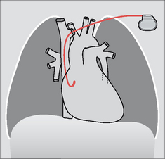
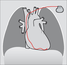
Figure 12.4 Optimal electrode position. Single chamber pacemaker. The tip of the ventricular lead is situated at the apex of the right ventricle.
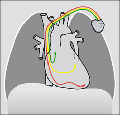
Figure 12.6 Optimal biventricular electrode positions. The third lead has entered, and extends along, the coronary sinus.
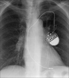
Figure 12.10 A pacemaker lead can be too taut. Consequently, there is a risk of the tip becoming displaced. (Retouched.)
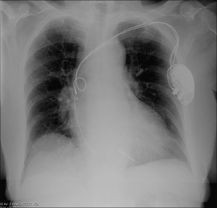
Figure 12.11 Right atrial lead. Leads should curve smoothly through the cardiac chambers. Any kinks, coils or secondary loops may result in electrode displacement. This lead is coiled. (Retouched.)
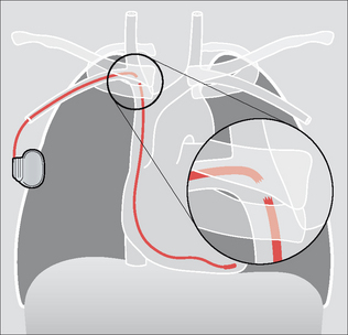
Figure 12.12 Pacemaker lead fracture at the pinch-off area between the first rib and the clavicle8. Be careful: some pacemakers have a non-opaque connector and this joint lucency can be misdiagnosed as representing a lead fracture2. Pacemakers are usually introduced on the left side because most people are right-handed. In this illustration it can be presumed that the patient was left-handed or that access to the left subclavian vein was compromised.
PACEMAKER CHECKLIST—THE LATERAL CXR
The electrode tip should be angled superiorly—i.e. positioned in the right atrial appendage (Figs 12.15 and 12.16).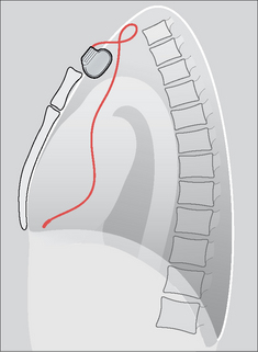
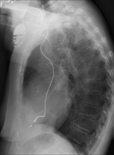
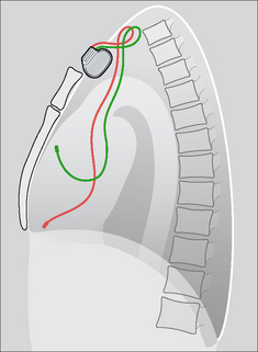
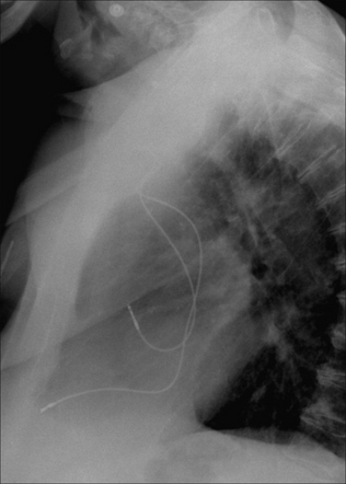
Figure 12.16 Dual chamber pacemaker. Normal positions of the atrial and ventricular leads. (Retouched.)
A RARE DISORDER—TWIDDLER’S SYNDROME2,8
Aetiology
Pacemaker in situ. Usually the patient has fiddled with the subcutaneous generator or with the lead. Fiddling/twiddling can cause the generator to become faulty, or the lead to fracture, or detachment of the electrode from the site of implantation. Sometimes the patient does not twiddle and the generator twists spontaneously because it is contained in an overlarge subcutaneous pocket.
The CXR
Comparison with previous post-placement CXRs may alert the physician prior to an impending failure. The generator, or a lead, may have changed position/direction. The CXR appearance of the generator (i.e. its position) may suggest the reason why the tip of the electrode has moved or why a lead fracture, from too much twisting, has occurred.
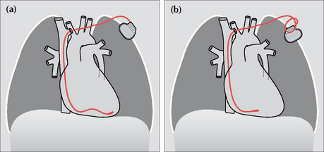
Figure 12.17 A twiddler. (a) Post-implantation and the ventricular lead is in good position. (b) Some months later the position of the generator box has changed, loops have developed just proximal to the subclavian vein, and the tip of the electrode is no longer at the apex of the right ventricle. One or more of these findings should suggest twiddler’s syndrome.
A RARE DISORDER—SUBCLAVIAN CRUSH SYNDROME9
Aetiology
Mechanical friction applied to a pacemaker lead can cause damage to the wire. Most commonly this friction occurs against the clavicle or the first rib; it is then referred to as a subclavian crush.
The CXR
The wire may be thinned or fractured. On all CXRs—when a pacemaker is in situ and has been introduced via a subclavian vein puncture—the pacemaker lead should be evaluated for any damage including erosion. The most vulnerable site is where the lead crosses underneath the clavicle (Fig. 12.12).
1. Bejvan SM, Ephron JH, Takasugi JE, et al. Imaging of cardiac pacemakers. AJR. 1997;169:1371-1379.
2. Burney K, Burchard F, Papouchado M, et al. Cardiac pacing systems and implantable cardiac defibrillators (ICDs): a radiological perspective of equipment, anatomy and complications. Clin Radiol. 2004;59:699-708.
3. Hertzberg BS, Chiles C, Ravin CE. Right atrial appendage pacing: radiographic considerations. AJR. 1985;145:31-33.
4. Gregoratos G, Abrams J, Epstein AE, et al. ACC/AHA/NASPE 2002 guideline update for implantation of cardiac pacemakers and anti-arrhythmia devices: summary article. A report of the American College of Cardiology/American Heart Association Task Force on Practice Guidelines. Circulation. 2002;106:2145-2161.
5. Morishima I, Sone T, Tsuboi H, et al. Follow up X-rays play a key role in detecting implantable cardioverter defibrillator lead fracture. Pacing Clin Electrophysiol. 2003;26:911-913.
6. Karthikeyan G. To Roentgen or not to Roentgen: Real dilemma or much ado about nothing? J Postgrad Med. 2005;51:96.
7. Bohm A, Pinter A, Duray G, et al. Complications due to abandoned non-infected pacemaker leads. Pacing Clin Electrophysiol. 2001;24:1721-1724.
8. Weiss D, Lorber A. Pacemaker twiddler’s syndrome. Int J Cardiol. 1987;15:357-360.
9. Noble SL, Burri H, Sunthorn H. Complete section of pacemaker lead due to subclavian crush. Med J Aust. 2005;182:643.