7
Radiographic Imaging
Vesna Balac, MS, RT(R)(MR)
On completion of this chapter, the student will be able to:
• Discuss primary, scatter, and remnant radiation.
• Describe the fundamentals of image production.
• Describe the three major categories of image receptor systems used today in radiography.
• Compare and contrast the latent image formation process for film-screen radiography, photostimulable phosphor systems, and indirect and direct capture digital radiography.
• Discuss image quality in terms of image receptor exposure, contrast, spatial resolution and distortion.
• Describe fluoroscopic imaging.
Key Terms
Attenuation Process by which a beam of radiation is reduced in energy when passing through tissue or other materials
Automatic Rescaling Process by which images are produced with uniform brightness and contrast, regardless of the amount of exposure
Brightness Function of a display monitor; changes image lightness/darkness
Computed Radiography (CR) Cassette-based digital radiography; the digital acquisition modality that uses storage phosphor plates to produce images
Contrast Difference between adjacent image receptor (IR) exposures on a radiographic image
Data Drop Condition due to extreme overexposure, which causes digital detector elements to become overwhelmed with photon energy and leads to drop of data during image reconstruction
Density Degree of darkening or blackness of exposed and processed photographic or radiographic film
Detector Saturation Data drop that involves areas or regions of the digital detector
Digital Radiography (DR) Cassette-less image receptor systems that convert x-ray energy into a digital electronic signal for manipulation and display
Direct Capture DR Devices that convert incident x-ray energy directly into an electrical signal, typically using a photoconductor as the x-ray absorber and a thin-film transistor as the signal collection area, which then sends the electrical signal to the computer for processing and viewing
Distortion Misrepresentation of the true size or shape of an object
Exposure Indicator (EI) Numeric representation of the quantity of exposure received by a digital image receptor
Exposure Latitude Range of exposures that can be used and still result in the capture of a diagnostic-quality image
Fog Undesirable exposure to the image receptor
Grid Device consisting of thin lead strips designed to permit primary radiation to pass while reducing scatter radiation by absorption
Half-Value Layer Amount of filtration necessary to reduce the intensity of the radiation beam to one half its original value
Image Receptor (IR) Medium used to capture the image for recording, such as x-ray film or a digital imaging plate
Indirect Capture DR Devices that absorb x-rays and convert them into light; the light is then detected by an area-charge-coupled device or thin-film transistor array in concert with photodiodes, and then converted into an electrical signal that is sent to the computer for processing and viewing
Intensifying Screen Layer of luminescent crystals placed inside a cassette to expose x-ray film efficiently and thereby significantly reduce patient dose
Inverse Square Law Mathematic formula that describes the relationship between radiation intensity and distance from the source of the radiation
Kilovolt Peak (kVp) Measure of the potential difference, which controls the quality and affects the quantity of x-ray photons produced in the x-ray tube
Latent Image Invisible image created after exposure but before processing
Milliampere-Seconds (mAs) Measurement of milliamperage multiplied by the exposure time in seconds, which controls the total quantity of x-ray photons produced in the x-ray tube
Penetrating Ability Ability of an x-ray beam to pass through an object; controlled by the kilovolt peak of the beam
Penumbra Fuzzy edge of an object as imaged radiographically; also known as image unsharpness
Photon Quantum or particle of radiant energy
Primary Radiation X-ray beam after it leaves the x-ray tube and before it reaches the object
Radiolucent Permitting the passage of x-rays or other forms of radiant energy with little attenuation
Radiopaque Not easily penetrable by x-rays or other forms of radiant energy
Remnant Radiation Radiation resulting after the x-ray beam exits the object
Scatter Radiation Radiation produced from x-ray photon interactions with matter in such a way that the resulting photons have continued in a different direction
Source-to-Image Distance (SID) Distance between the source of the x-rays (usually the focal spot of the x-ray tube) and the image receptor
Spatial Resolution Degree of accuracy of the structural lines actually recorded in the image
Umbra True edge of an object as imaged radiographically
Window Level Image manipulation parameter that changes image brightness on the display monitor, usually through the use of a mouse
Window Width Image manipulation parameter that changes image contrast on the display monitor, usually through the use of a mouse
Radiographic imaging is an essential but complicated subject. There are many concepts that one must not only understand but also apply in the clinical environment. This chapter is intended to give an overview of the most common image receptor systems used in radiography, the image formation process, and the image quality factors essential to producing a diagnostic radiographic image. It will present many basic concepts that will be expanded in other courses. It is important to grasp the basic definitions and concepts before moving on to the more involved topics.
Image Production
When x-rays were discovered in 1895, the medical community almost immediately realized the value of this discovery. Seeing inside of the human body became possible. In the following years, capturing the image produced by x-rays in a format allowing for storage and repeated viewing had become the task of the radiologic technologist. Despite the almost daily advances within the field of radiology, the basic mechanism of x-ray production has not changed a great deal. A beam of x-rays, mechanically produced by passing high voltage through a cathode ray tube, traverses a patient and is partially absorbed in the process. A device called an image receptor (IR) intercepts the x-ray photons that are able to exit the patient. Multiple different IR systems are used in radiography, including film-screen systems, computed radiography (CR) cassette-based systems, digital radiography (DR) cassette-less systems, and fluoroscopic imaging systems.
Basically, the following four requirements exist for the production of x-rays:
The vacuum removes all of the air, so gas molecules will not interfere with the production of x-rays. When the electrons strike the target, x-ray photons are produced; however, less than 1% of this production is actually x-rays; the remaining 99% or more is heat.
The beam of x-ray photons is generated by the careful selection of technical exposure factors by the radiographer. These photons then exit the x-ray tube during the exposure. This beam of photons, before it interacts with the patient’s body, is called primary radiation. When the primary beam passes through a patient, the individual x-ray photons interact with the various materials that make up the human body. Depending on the characteristics of these materials, the quantities of the photons are lessened by differing degrees as they pass through matter. The resulting beam that is able to exit from the patient is called exit or remnant radiation. This remnant radiation produces an image in the IR.
Along the way, an x-ray photon may interact with the body’s matter in such a way that the resulting photon continues its travel in a different direction. This type of radiation may or may not be able to reach the IR, but it does not carry any useful information. Scatter radiation is the term generally used to describe this type of nondiagnostic radiation. Attenuation is the process by which the nature of the primary radiation is changed (partially absorbed or scattered) as it travels through the patient. The x-ray beam is attenuated differently, depending on the type of body tissue irradiated. For example, bone tissue, being more densely packed and made of harder material, attenuates the beam to a greater degree than soft tissue of the same thickness. This difference in attenuation allows for the formation of radiographic images. The entire path of a beam of x-radiation is shown in Fig. 7.1.

In describing the relative ease with which x-ray photons may pass through matter of different types, two terms are commonly used. Radiolucent materials allow x-ray photons to pass through comparatively easily; translucent panes of glass allow the passage of light. Radiopaque materials are not easily traversed by x-ray photons, just as panes of tinted glass do not allow the full amount of light to pass through. Thus bone is described as a relatively radiopaque tissue, whereas air is described as relatively radiolucent.
The radiographer directly controls image quality. Selection of the proper exposure factors for each individual examination is necessary to produce a high-quality diagnostic radiograph. The exposure factors under the control of the radiographer, often referred to as technique or prime factors, include the following:
- 1. Milliampere-seconds (mAs) is the parameter that controls the amount of x-radiation produced by the x-ray tube; it is the product of milliamperage (mA) multiplied by seconds. It directly controls the quantity of x-ray photons produced. mA is a measure of the electrical current passing through the x-ray tube. Time (in seconds) is a measure of the duration of the exposure and may be expressed in decimals, fractions, or millisecond values.
- 2. Kilovolt peak (kVp) is a measure of the electrical pressure (potential difference) forcing the current through the tube. It controls the penetrating ability of the beam and primarily affects the quality but also the quantity of the x-ray photons produced.
- 3. Source-to-image distance (SID) is the distance between the point of x-ray emission in the x-ray tube (the focal spot) and the IR. It affects the relative intensity of the radiation that reaches the IR and affects the geometric properties of the image. This measurement has also been known as focal-film distance or target-to-film distance.
Other factors that can be controlled by the radiographer include focal spot size, primary beam configuration, quantity and quality of scatter, and speed of the IR.
Diagnostic radiography makes use of the differential attenuation of a beam of x-rays by various types of body tissue. In this way, information can be gained about the anatomy, physiology, and pathology of many of the body’s organ systems. The degree to which the x-rays are attenuated depends on patient thickness and tissue characteristics, such as cell composition, relative atomic number, thickness, and cell density. In addition, pathologic conditions can change the way in which the radiation is attenuated. A thick, dense tissue with a relatively high atomic number, such as bone, attenuates the beam to a greater degree than does a thin, less dense tissue with a low atomic number, such as fat. Bone prevents the easy passage of the x-ray photons, resulting in less IR exposure; therefore, bone is represented as a lighter shade of gray (almost white in some instances), and it can be described as an area of decreased IR exposure (in CR and DR) or radiographic density (in film-based systems), on the image.
Because radiography is actually the investigation of tissue characteristics, attempting to standardize all other factors affecting image quality so that the subject is the only variable makes sense. Technique charts, automatic exposure control, accurate positioning, and standard imaging protocols are useful in this regard.
Image Receptor Systems
Once the attenuated beam has exited the patient as remnant radiation, the information it carries about the types of tissue the beam has traversed must be translated from an energy message to a visual image that can be viewed and stored. X-ray photons have the ability to produce changes in photographic film, photostimulable phosphors, and photoconductor materials, such as amorphous selenium (a-Se). Various IR systems exist, including film-screen systems, digital cassette-based systems, and digital cassette-less systems. Historically, film was the primary recording medium; however, almost all film-based systems have now been replaced with CR and DR systems.
Film-Screen Systems
Special film, manufactured to be particularly sensitive to x-radiation and certain colors of light radiation, is used to capture the energy message carried by the remnant beam and to convert it into an image. After the energy strikes it, the film must be processed before an image can be seen. A useful analogy is that of regular photographic film, in which the camera is loaded with the film, which then receives the light reflecting off the subject. When the roll of film is finished, it is rewound into a light-tight canister, developed, and printed. The printed image can then be viewed and stored. The image is not visible before processing because it is stored in a form that is not visible.
Radiographic film is similar. The remnant x-ray photons carry an energy representation of the object of interest that strikes the film emulsion, causing a transfer of energy. This image is stored in the emulsion until it is processed. This invisible image is called the latent image. Once the film has been processed, a visual image appears. The correct term to describe an image produced by x-ray photons on a piece of film is a radiograph.
Intensifying screens are thin layers of polyester plastic coated with layers of luminescent (light-emitting) phosphor crystals. The screens are mounted in a cassette, and the film is placed inside. Typically, radiographic film has an emulsion coating on both sides and is known as duplitized or double-emulsion film. Duplitized film is designed to be used with two intensifying screens for the most efficient performance. Estimates indicate that more than 99% of the photographic effect on a film-screen radiograph is from screen light, with the remaining effect caused by the direct action of x-ray photons.
Digital Cassette Systems
Photostimulable Phosphor Systems
Also known as CR or cassette-based DR, photostimulable phosphor systems make use of the digital acquisition modality in which photostimulable storage phosphor (PSP) plates are used to produce radiographic images. PSP plates are also referred to as imaging plates (IPs). CR can be used in standard radiographic rooms just like film-screen systems; therefore, no special changes are needed to the x-ray rooms. The new equipment that is required includes the CR cassettes and phosphor plates, the CR readers, and the image-display workstations.
The storage phosphor plates are very similar in makeup to intensifying screens used in film-screen radiography. The biggest difference is that the storage phosphor plate can store a portion of the incident x-ray energy it traps within the material for later readout. The reader releases the stored energy in the form of light and converts it into an electrical signal, which is then digitized.
The CR cassette looks like the film-screen cassette. It consists of a durable, lightweight plastic material. The cassette is backed by a thin sheet of aluminum that absorbs x-rays. Instead of intensifying screens inside, there is antistatic material (usually felt) that protects against static electricity buildup, dust collection, and mechanical damage to the plate.
In CR, the radiographic image is recorded on a thin sheet of plastic known as the imaging plate. The IP consists of several layers, including the protective layer, phosphor layer, conductive layer, light-shield layer, support layer, and backing layer. The cassette also contains a barcode label or barcode sticker on the cassette or on the IP (viewed through a window in the cassette), which allows the technologist to match the image information with the patient-identifying barcode on the examination request.
With CR systems, no chemical processor or darkroom is necessary. Instead, after exposure, the cassette is fed into a reader (Fig. 7.2) that removes the IP and scans it with a laser to release the stored electrons.
There is no change in how the patient is x-rayed compared with film-screen radiography. The patient is positioned using appropriate positioning techniques, and the cassette is placed either on the tabletop or within the table or upright Bucky. Proper kVp, mAs, and distance must still be employed to produce a high-quality image. The biggest difference lies in how the exposure is recorded. In CR, the remnant beam interacts with electrons in the barium fluorohalide crystals contained within the IP. This interaction stimulates, or gives energy to, electrons in the crystals, allowing them to enter the conductive layer, where they are trapped in an area of the crystal known as the phosphor center. This trapped signal will remain for hours, even days, although deterioration begins almost immediately. In fact, the trapped signal is never completely lost. However, the residual trapped electrons are so few that they do not interfere with subsequent exposures.
kVp, mAs, and distance are selected for reasons similar to those for conventional film-screen radiography; kVp must be chosen for penetration and somewhat for the type and amount of contrast desired. Early on, manufacturers stated that the minimum kVp should be no less than 70. This is no longer true. The kVp values now range from approximately 45 to 120. It is not recommended that kVp values less than 45 or greater than 120 be used, because those values may be inconsistent and produce too little or too much excitation of the phosphors. Remember, the process of attenuation of the x-ray beam is exactly the same as in film-screen radiography. It takes the same kVp to penetrate the abdomen with CR systems as it did with film-screen systems.

From Ballinger PW, Frank ED. Merrill’s Atlas of Radiographic Positions and Radiologic Procedures. 10th ed. St. Louis: Mosby; 2003.
The mAs is selected according to the number of photons needed for a particular part. If there are too few photons, regardless of the kVp chosen, the result will be a lack of IR exposure to create sufficient phosphor stimulation. When insufficient light is emitted from the phosphors, it produces an image that is grainy, a condition known as quantum mottle or quantum noise (Fig. 7.3).
Digital Cassette-less Systems
Digital cassette-less systems use various materials for detecting the x-ray signal. The detectors are permanently enclosed in a rigid protective housing. Both direct capture DR and indirect capture DR detectors are used with these systems.
Direct Capture
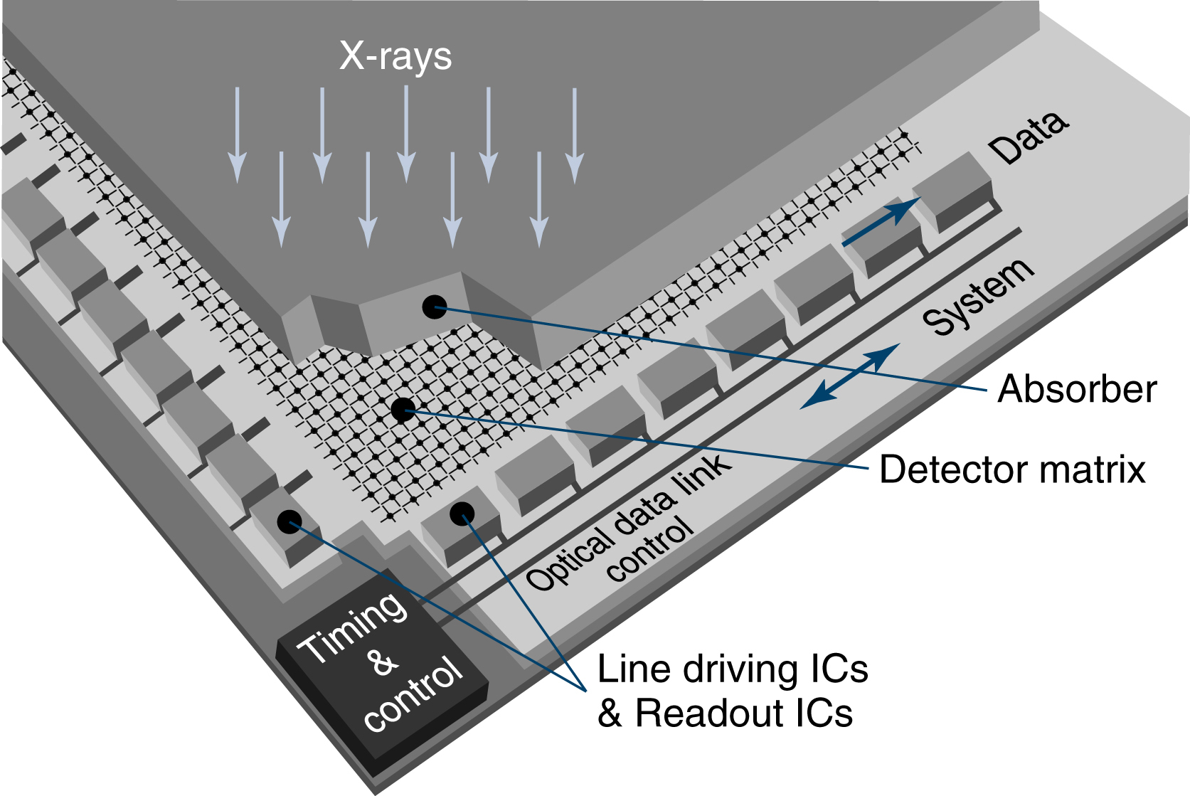
In direct capture, x-ray photons are absorbed by the coating material and immediately converted into an electrical signal. The DR detector has a radiation-conversion material or scintillator, typically made of amorphous selenium (a-Se). This material absorbs x-rays and converts them to electrons, which are stored in the thin-film transistor (TFT) detectors (Fig. 7.4). The TFT is an array of small (approximately 100 to 200 μm) pixels. A pixel is a single picture element, and a matrix is a rectangular series of pixels. The degree of accuracy of the structural lines recorded, known as spatial resolution is determined by the individual size of each pixel in a digital image. Each pixel contains a photodiode that absorbs the electrons and generates electrical charges. More than 1 million pixels can be read and converted to a composite digital image in less than 1 second.

Indirect Capture
Indirect capture detectors are similar to direct detectors in that they may use TFT technology. Unlike direct capture, indirect capture is a two-step process: x-rays photons are first converted to light using a scintillator, and that light is then converted to an electric signal.
The scintillation layer in the IP is excited by x-ray photons, and the scintillator reacts by producing visible light. This visible light then strikes the amorphous silicon, which conducts electrons down into the detector directly below the area where the light struck. There are two types of indirect conversion devices: the charge-coupled device (CCD) and the TFT array. The CCD uses a chip to convert light photons to electrical charge. The TFT array isolates each pixel element and reacts like a switch to send the electrical charges to the image processor. As with direct capture, more than 1 million pixels can be read and converted to a composite digital image in less than 1 second (Fig. 7.5).
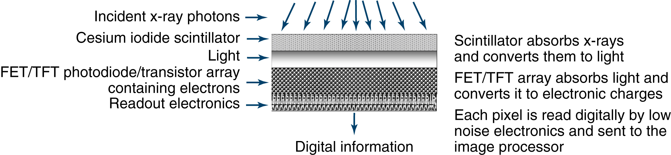
Image Quality Factors
The acceptance characteristics of a diagnostic-quality image, termed image quality factors, fall into two main categories: (1) photographic qualities affecting the visibility of the image and (2) geometric qualities affecting the sharpness and accuracy of the image. There are four primary image quality factors. Two of these are photographic in nature: IR exposure and contrast. As an image quality factor, density was the term that was used to reflect the impact of IR exposure to the radiographic film. Radiographic density is defined as the overall blackening of film emulsion in response to this exposure. With digital systems, this important image quality factor has not changed but can be expressed simply as IR exposure, because film is no longer the receptor of the image. In the digital environment, brightness is a monitor control function that can change the lightness and darkness of the image, but it is not related to IR exposure. Contrast is the visible difference between adjacent IR exposures, or the ratio of black to white. The two geometric quality factors are spatial resolution (also known as sharpness or recorded detail), the distinct representation of an object’s true borders or edges, and distortion, the misrepresentation of the true size or shape of an object.
A proper balance between the photographic and geometric properties of an image results in good image quality. The geometric properties allow the size, shape, and edges of the object of interest to be accurately represented, whereas the photographic properties allow these carefully reproduced characteristics to be seen.
By way of illustration, imagine that you are trying to take a snapshot of an ornately carved stone. You want every detail to be captured, so you take extra trouble to focus carefully. To make certain of success, you make three exposures, each at a different setting. When the photograph has been processed, you examine your three photos. One photo is perfectly exposed, and you are able to see every important detail in the carving. The second is too dark, and any detail is hard to distinguish. The third is too light, and again, the details of the carving are impossible to see. Consider the two poorly exposed photographs. Just because a photograph is too dark or too light, does that mean that good detail sharpness is not present? These problems of overexposure and underexposure affect the visibility but not the sharpness of the detail.
You return to the carving, intending to use the proper exposure setting to get more photographs. This time, you forget to focus the camera properly, or you move while pressing the shutter. The resultant photograph has beautiful photographic properties, but is fuzzy and blurred. This photograph can be said to possess good visibility but poor sharpness of detail. The desired image should have good levels of both characteristics (Fig. 7.6).
When images are evaluated, sharpness and visibility of detail must be examined to assess overall quality. The photographic factors that control visibility of detail are considered first.
Photographic Qualities
Image Receptor Exposure
In film-screen radiography, density has always been the result of IR exposure to the radiographic film. When film is replaced by a digital radiography system, IR exposure becomes the critical factor affecting image quality, and the radiographer must closely monitor the IR exposure values to ensure a good image. Radiographic density can be described technically as a comparison of the light incident on the film to the light transmitted through the film. If a digital image is printed to hard-copy film, the traditional term density can still be used.
When a hard copy radiograph is viewed on a viewbox, the incident light is transmitted more easily through the light gray areas than through the darker areas. The darker areas that block the transmission of light are said to have greater radiographic density. Although it can be easily measured scientifically with a densitometer, density is often a subjective measurement, judged by the human eye. A radiograph must possess the proper IR exposure to present adequate visibility of detail to the viewer in the same way that a photograph should not be overexposed or underexposed to do justice to its subject. In many instances, a radiologist’s use of the term density refers to anatomic density and not to radiographic density. A report noting an increased density in the right lung field should be interpreted to mean that the lung tissue is denser than other tissues. The IR exposure, or radiographic density on a film, in such an area would therefore be decreased because the denser tissue would absorb more of the x-ray beam than the tissue that is less dense. Many variables can affect IR exposure, including mAs, patient factors, kVp, distance, beam modification, grids, and IRs (Table 7.1).

TABLE 7.1
| Milliampere seconds |
| Patient factors |
| Kilovolt peak |
| Distance |
| Beam modification |
| Grids |
| Image receptors |
Milliampere-Seconds
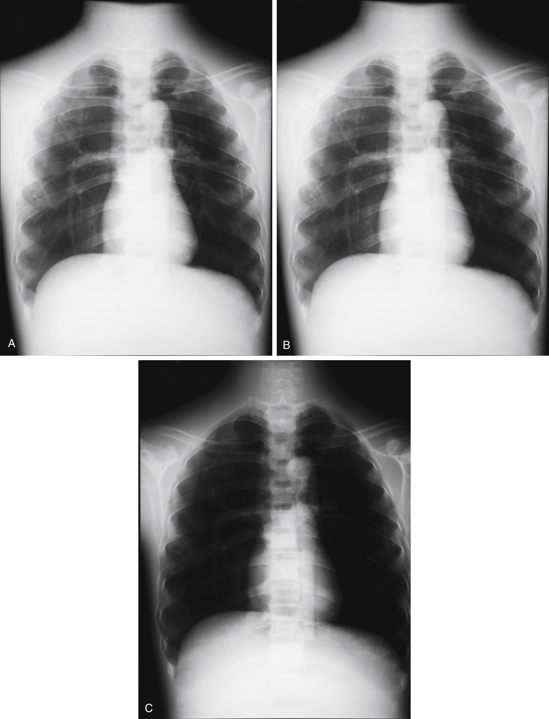
The number of electrons that flow from cathode to anode in the x-ray tube is controlled by mAs. This process in turn controls the number of x-ray photons produced. The greater the number of x-ray photons generated, the greater will be the resultant IR exposure. Increasing the number of x-ray photons produced increases the exposure (in milliroentgens [mR]) in a directly proportional relationship, and this results in an overall increase in IR exposure. mAs is the product of mA and time. Any combination of mA and time producing equivalent mAs values should produce equivalent IR exposures. This process is known as mAs reciprocity.

Examples


The mAs, mA, and time factors are all directly related to image receptor exposure, as well as patient exposure. These effects can also be stated as follows:
The radiographs in Fig. 7.7 illustrate these effects.
Example


Patient Factors
Various patient factors affect IR exposure. Patient size and thickness, the predominant atomic numbers of the materials (which may include contrast media intentionally introduced into the body), pathologic conditions, anomalies, temporarily compressed tissues, and a number of other techniques all change the subject density of the object being examined. As subject density increases, IR exposure decreases, and vice versa.
Kilovolt Peak
In addition to the number of x-ray photons produced, the relative strength of the photons must be considered. An x-ray photon of very low energy would have difficulty passing through dense body tissue. Conversely, this same low-energy photon would pass easily through less dense tissue. This characteristic is referred to as the penetrating ability of an x-ray beam. Each average body part can be shown to best advantage by using an optimal kVp setting as a guideline.
The kVp setting determines the highest energy level, or the peak, possible for the photons within that beam. Most of the photons are, in fact, below the peak kilovoltage, covering a range from zero to peak value. The x-ray beam is described as polyenergetic or heterogeneous for this reason.
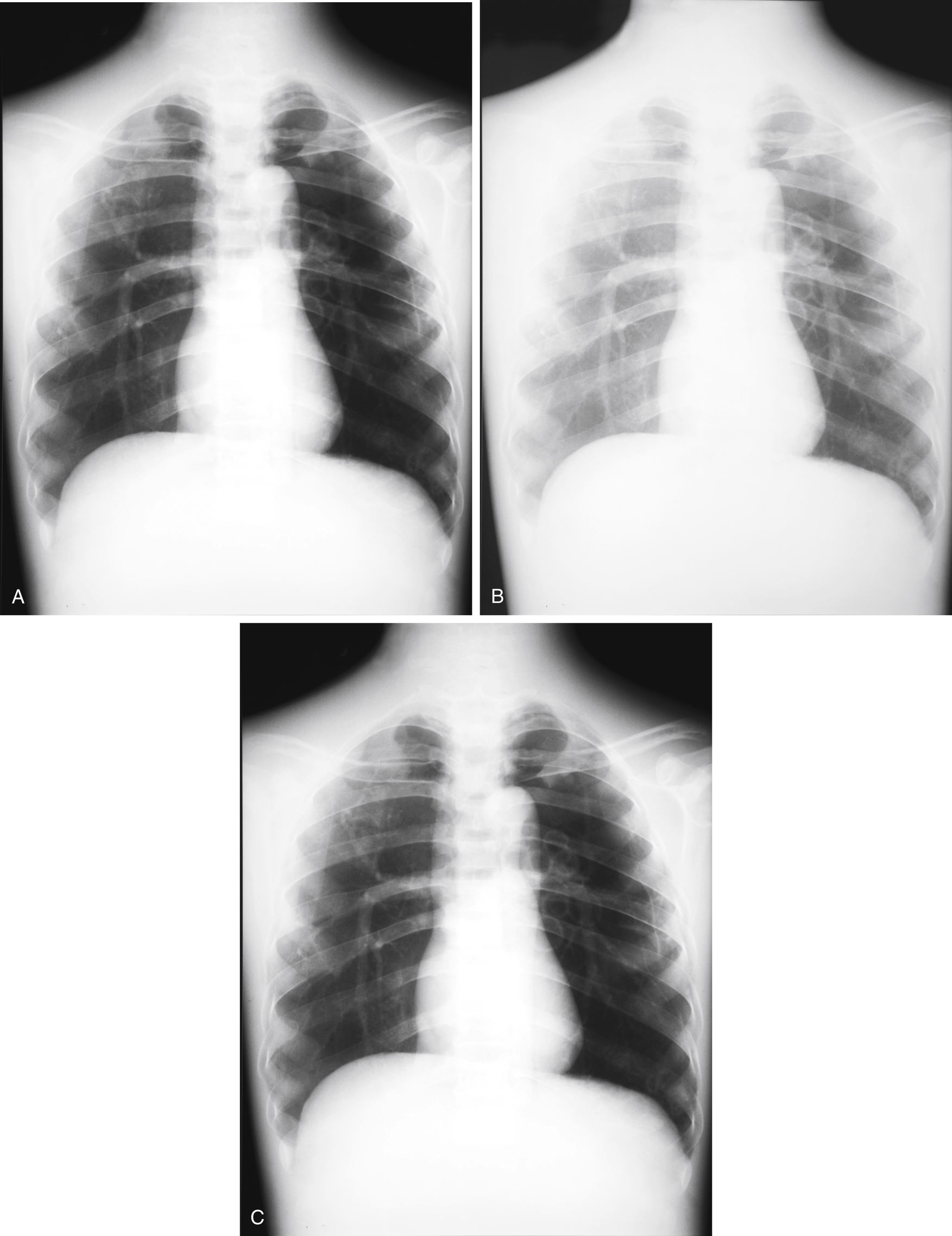
The relationship between kVp and exposure is not as simple as that of mAs. As kVp increases, IR exposure increases but not in direct proportion. The general rule of thumb to account for the change in IR exposure relative to change in kVp is called the 15% rule. Increasing kVp 15% will approximately double IR exposure. Decreasing kVp 15% will approximately halve IR exposure.
For example, imagine that the original kVp is 75. Of the original kVp (75), 15% equals 11.25 or approximately 11. If we want to double the IR exposure using the kVp, 11 kVp should be added to the original selection (75), which would result in 86 kVp. If we want to halve the IR exposure using the kVp, then 11 kVp should be subtracted from the original (75), which would then equal 64 kVp.
Using this rule to change kVp while maintaining the same IR exposure is also possible. This process is done by changing the mAs to compensate for the exposure change caused by the change in kVp. When this adjustment is made, the change in kVp does not change the quantity of the exposure—only the spectrum or energy of the photons. kVp can be changed while maintaining the same IR exposure as follows:
Example
To maintain the original image receptor exposure, what new value of mAs is necessary when changing from 75 kVp and 50mAs to 86 kVp?


Because the kVp increased 15%, the mAs must be halved to maintain the original image receptor exposure:

The radiographs in Fig. 7.8 illustrate these effects.

Distance
A beam of radiation obeys many of the same laws that light does. If a flashlight beam is projected onto a wall, the relative intensity of the light increases as it is moved closer to the wall. The intensity increases as the distance decreases. As the flashlight is moved farther from the wall, the intensity of the light decreases as the distance increases. This characteristic is described as an inverse relationship.
The same relation holds true for an x-ray beam. If all other factors are equal, the greater the distance the photons have to travel, the less chance they have of reaching the IR because of the divergence of the beam (Fig. 7.9). This relationship means that the same exposure factors used at a greater distance would result in reduced IR exposure. The relationship between distance and exposure is described by the inverse square law: the intensity of radiation (as measured in mR) is inversely proportional to the square of the distance from the source. In other words, as an example, if the distance is doubled, the intensity decreases to one-fourth of the original. The mathematic expression of the inverse square law is as follows:

where
Example
If the intensity of the beam is 40 mR at the original distance of 40 cm, what will the intensity be if the new distance is 20 cm?


Note that decreasing the distance by half causes the intensity to increase by a factor of 4.
The inverse square law describes the effect of a change in distance on beam intensity, but the radiographer would frequently like to be able to compensate for a necessary change in distance. This compensation may be accomplished by using a conversion of the inverse square law known as the exposure maintenance formula. This formula is actually a direct square law. The mathematic expression of the exposure maintenance formula is as follows:

where
Because mAs, mA, and time are all directly proportional to beam intensity, this formula may be used to derive any of these three factors.
Example
If a radiograph produced at 72 inches SID using 20 mAs must be repeated at 36 inches SID, what new mAs setting is necessary to maintain the same image receptor exposure?


Beam Modification
Anything that changes the nature of the radiation beam, apart from the factors already discussed, is referred to as beam modification. The beam may be modified before it enters the patient, in which case it is called primary beam modification, or after it exits the patient, in which case it is generally known as scatter control.
The primary beam can be adjusted by changing filtration and beam limitation. Filtration is the use of attenuating material, usually aluminum, between the x-ray tube and the patient. This substance mainly removes very-low-energy nondiagnostic x-ray photons in the primary beam to decrease patient exposure. As more material is placed in the path of the beam, the resultant intensity decreases. For example, a bare light bulb glows with a specific intensity. Placing a paper shade over the bulb filters out some of the light, thereby reducing its intensity. With all other factors equal, the same exposure factors used with 4 mm of filtration would produce less IR exposure than if used with only 2 mm of filtration.
The amount of attenuating material required to reduce the intensity of a beam to half the original value is referred to as the half-value layer. Because aluminum is the most common material used for filtration in diagnostic radiography, half-value layer is usually expressed in terms of millimeters of aluminum equivalency (mm Al/Eq).
Beam limitation is the use of devices, such as a collimator, to confine the x-ray beam to the area of interest, thereby reducing exposure to body parts other than those under examination. In addition to patient protection, beam limitation dramatically affects radiographic quality. During the transit of an x-ray photon through matter, the probability that the photon will collide with an atom is high. This collision may result in a change in direction, as well as a decrease in the energy of the photon. This scattered photon is virtually useless from a diagnostic standpoint and contributes only to patient dose. This type of photon is usually described as scatter radiation. If scatter radiation reaches the IR, it is not carrying useful information. Scattered photons that strike the IR degrade the quality of the image by contributing unwanted exposure known as fog.
By limiting the size and shape of the primary beam to the area of interest, we are decreasing the probability of the production of scatter radiation. Scatter can never be eliminated, but its effect can be lessened. In fact, scatter accounts for a large percentage of the IR exposure of the image. By restricting the primary beam and decreasing scatter, we are, in effect, subtracting photons from the remnant beam. Therefore a decrease in scatter causes a decrease in IR exposure.
Grids
Despite the careful use of primary beam modification, once the beam enters the patient, scatter radiation is produced. As stated previously, the more scatter that reaches the IR as fog, the poorer the appreciation of the details. A grid is a device that is designed to remove as many scattered photons exiting the patient as possible before they reach the IR. A grid consists of thin radiopaque lead strips interspersed with radiolucent spacing material. The grid is placed between the patient and the IR to intercept scattered photons, which, by definition, have been diverted from their original paths. Increasing the lead in a grid increases its ability to remove scatter from the remnant beam. Decreasing the amount of scatter enhances the radiographic contrast. However, the additional lead in the grid also requires increased exposure factor settings, which increases the radiation dose to the patient.
Grids are generally described according to grid ratio, the ratio of the height of the lead strips to the distance between them, and grid frequency, the number of grid lines per inch or centimeter. Grid ratios commonly range from 5:1 to 16:1, with the higher ratio grid able to prevent more scattered photons from reaching the IR. Grid frequencies are generally 85 to 200 lines per inch. Because the grid reduces the number of photons reaching the IR, it also causes a decrease in IR exposure. All other factors being equal, if the same exposure factors are used with a 5:1 grid and a 10:1 grid, the 10:1 grid produces an image with less IR exposure.
Image Receptors
With digital IRs, there are several key factors that must be considered when evaluating proper IR exposure. These include exposure latitude, the exposure indicator (EI), automatic rescaling, and window leveling.
Exposure latitude refers to the range of exposures that can be used and still result in the capture of a diagnostic-quality image. The exposure latitude is greater for digital imaging receptors than for film-screen exposures. The greater exposure latitude is a result of the higher dynamic range of the receptors. Dynamic range refers to the IR’s ability to respond to the exposure. With film-screen systems, overexposure and underexposure are quite evident and are reflected in an image on a film that is too light or too dark. In digital radiography systems, this difference, which is easy to see on film, is not evident on the display monitor. In CR and DR, if the exposure is more than 50% below the ideal exposure, quantum mottle results. The biggest difference between digital and film-screen radiography lies in the ability to manipulate the digitized pixel values, which allows for greater exposure latitude.
EI is a numeric representation of the quantity of exposure received by a digital IR. The total signal is not a measure of the dose to the patient, but rather indicates how much radiation was absorbed by the IR, which gives only an idea of what the patient received. The base EI number for all systems designates the middle of the detector operating range.
For the Fuji (Tokyo, Japan), Philips (Eindhoven, the Netherlands), and Konica Minolta (Tokyo, Japan) systems, the EI is known as the S or sensitivity number. It is the amount of luminescence emitted at 1 mR at 80 kVp and has a value of 200. The higher the S number with these systems, the lower the exposure. For example, an S number of 400 is half the exposure of an S number of 200, and an S number of 100 is twice the exposure of an S number of 200. The numbers have an inverse relationship to the amount of IR exposure.
Carestream (Rochester, New York) uses the term exposure index. A 1-mR exposure at 80 kVp combined with aluminum or copper filtration yields an EI number of 2000. An EI number plus 300 (EI + 300) is equal to a doubling of exposure, and an EI number minus 300 (EI − 300) is equal to halving the exposure. The numbers for the Carestream system have a direct relationship to the amount of exposure so that each change of 300 results in change in exposure by a factor of 2. This is based on logarithms, but instead of using 0.3 (as is used in conventional radiographic characteristic curves) as a change by a factor of 2, the larger number 300 is used. This is also a direct relationship—the higher the EI, the higher the IR exposure.
TABLE 7.2

From Carter C, Veale B. Digital Radiography and PACS. St. Louis: Mosby; 2010.
TABLE 7.3
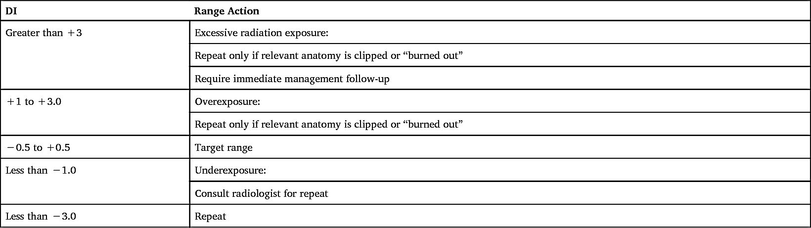
DI, Deviation index. From American Association of Physicists in Medicine. An exposure indicator for digital radiography: Report of AAPM task group 116, 2009.
The term for EI for an Agfa (Mortsel, Belgium) system is the logarithm of the median exposure (lgM). An exposure of 1 mR at 75 kVp with copper filtration yields an lgM number of 2.6. Each step of 0.3 above or below 2.6 equals an exposure factor of 2. For example, an lgM of 2.9 equals twice the exposure of 2.6 lgM, and an lgM of 2.3 equals an exposure half that of 2.6 lgM. The relationship between exposure and lgM is direct.
Digital imaging system manufacturers use different methods to numerically represent exposure values (Table 7.2). This lack of a universal system has been a source of confusion for technologists, and consequently there has been a need to standardize EIs. The American Association of Physicists in Medicine is actively working on solving this issue, and their intent is to establish a standard scale that would be accepted by all manufacturers. Once this scale is accepted, the users would establish a target value for each examination, based on their system. The deviation index (DI) would be used in conjunction to determine if the appropriate radiographic technique factors were used during an examination. The DI can be defined as a comparison of the target value with the actual exposure recorded by the IR (Table 7.3).
Automatic rescaling is used when exposure is greater or less than what is needed to produce a diagnostic image. Automatic rescaling means that images are displayed with uniform brightness and contrast, regardless of the amount of exposure to the IR. Problems occur with automatic rescaling when too little or too much exposure is used. Quantum mottle or noise is often seen when not enough exposure is used for a particular anatomic body part. Too much exposure can detract from image quality and lead to data drop. Data drop is a condition that causes digital detector elements to become overwhelmed with photon energy, which leads to drop of data during image reconstruction. Data drop can occur over an entire area of the detector, leading to detector saturation. Therefore, detector saturation can be described as data drop that involves areas or regions of the detector. Data drop and detector saturation can present serious clinical issues for the interpreting physician. Therefore, rescaling is no substitute for appropriate technical factors. One should not rely on the system to scale the image into an appropriate brightness and contrast through rescaling when higher-than-recommended mAs values are used for a particular body part, to avoid repeats.
TABLE 7.4
| Kilovolt peak |
| Patient factors |
| Contrast media |
| Milliampere-seconds |
| Beam modification |
| Image receptor |
| Grids |
Windowing is a processing operation that controls brightness and contrast on the monitor. Window level controls image brightness, and window width controls contrast (the ratio of black to white). The user can quickly manipulate both by using a mouse. Care should be taken, because this may be a permanent change depending on the vendor, and could have a negative impact on the stored image in the picture archiving and communication system.
Contrast
The second photographic image quality factor is contrast. Contrast is the visible difference between adjacent IR exposures. An object may be accurately represented on an image, but if it cannot be distinguished from the objects surrounding it, then the eye will not adequately appreciate the object. Proper contrast enhances the visibility of detail. Contrast can be understood by recalling the story of the little boy who was asked to draw a picture in art class. After laboring for some time, he presented a sheet of completely white paper to the teacher. The puzzled teacher asked what the picture was supposed to represent, to which the little boy replied, “It’s a white horse eating marshmallows in a snowstorm.” Of course, because no contrast existed between the different densities, the teacher failed to see the image the child described.
Many factors affect contrast, including kVp, patient factors, contrast media, mAs, beam modification, IRs, and grids (Table 7.4).

Kilovolt Peak
The chief controlling factor of contrast had historically been kVp. Adjusting the kVp controls the penetrating ability of the x-ray beam. Higher kVp is required to penetrate bony tissue than soft tissue. It is important to understand that the relationship between the kVp and contrast has changed with the use of CR and DR technologies, and the old rules no longer apply. This is due to computer software’s ability to manipulate the image by altering the amount of contrast demonstrated. Therefore, kVp does not have the impact on the final image contrast as it did with film-screen. However, it is important to note that kVp still controls the signal differences in the digital detector and should be selected for the desired level of subject contrast. Unlike image contrast, subject contrast cannot be manipulated with post-processing because it is directly influenced by the attenuation properties of the tissues.
Contrast is the difference between the range of adjacent IR exposures represented on an image. These IR exposures fall into a range from darkest to lightest gray. This range of gray tones is known as the scale of contrast. The fewer the gray tones present, the greater the difference between individual IR exposures. Consider the difference between maximum and minimum IR exposures. In Fig. 7.10, if the 60-kVp strip goes from dark to light in five steps, whereas the 120-kVp strip goes from dark to light in more steps, the difference between the individual IR exposure steps in the 120-kVp strip will be less than that in the 60-kVp strip.
Images with relatively few gray tones are said to possess high contrast, short-scale contrast, and narrow latitude. Images with greater numbers of gray tones are said to possess low contrast, long-scale contrast, and wide latitude. Remember that contrast is a relative measure. No absolute standards of high or low contrast exist; only comparisons between images can be made.
TABLE 7.5
A higher energy beam tends to penetrate objects in its path more easily and thus produces a wider range of gray tones. Table 7.5 outlines these relationships.
Patient Factors
As described in the section on IR exposure, the tissues that make up the human body attenuate the beam of radiation to differing degrees. This differential attenuation is the basis for image contrast. If two objects represented on an image have similar tissue densities, they produce similar IR exposures. This is often the case in radiography of the abdominal organs. Distinguishing details within these similar tissue densities would be difficult. This is an example of a body part with low subject contrast. Other body parts possess high subject contrast. In radiography of the chest, the bony tissue of the ribs has much greater tissue density than the surrounding air-filled lung tissue. The resulting IR exposures are therefore different and easily distinguishable.
Contrast Media
Enhancing the inherent contrast is sometimes possible through the use of contrast media. Contrast media are substances that attenuate the beam to a different degree than the surrounding tissue. Examples of contrast media used in radiography include barium and iodine compounds, and air. Filling the stomach and intestine with barium compound allows these structures to be visualized and examined radiographically. The kidneys filter an intravenous injection of iodine compound, allowing examination of the urinary tract as the compound is excreted. Because the contrast medium introduces an additional subject density to the body, technical factors, particularly kVp, must be adjusted for adequate penetration.
Milliampere-Seconds
mAs alters IR exposure, and therefore, influences contrast. If an image is grossly overexposed or underexposed, then contrast is affected. If exposure is maintained, then mAs will have no effect on the contrast of the image. With film, under- or over-exposure was clearly evident in the resultant image. For digital systems, the exposure indicator should be in the acceptable range to assure that the detector received the correct exposure. No increase in mAs can compensate for inadequate penetration.
Beam Modification
One of the primary purposes of beam modification is scatter control. Scattered radiation allowed to reach the IR produces nondiagnostic exposures referred to as fog. Removal of fog results in the loss of some specific gray tones. Decreasing the number of gray tones, by definition, causes a move toward higher contrast. Anything that decreases scatter increases contrast.
Image Receptors
With digital image detector systems, the traditional relationship between contrast and exposure variables does not exist. With digital systems, contrast is determined through digital processing, which sets the range of information that will be supplied to the monitor. The information is displayed in a range of brightness, which can then be adjusted through the manipulation of the window width. Even though digital processing controls image contrast, sufficient differences in exposure to the receptor are necessary. Therefore, the radiographer still must set proper exposure factors to create an acceptable image quality with minimum exposure of the patient.

Grids
Because grids absorb scatter radiation, they function to improve contrast. Grids are available in a diverse range of ratios and frequencies. These choices allow the radiographer to select how much scatter radiation is to be eliminated, and thereby control the visible level of contrast on the image. Because of the high sensitivity of digital detectors to scatter radiation, the use of a grid is much more critical than in film-screen radiography. When possible, the highest grid frequency available should be used with digital imaging to avoid certain grid errors.
Geometric Qualities
Spatial Resolution
The sharpness with which an object’s structural edges are represented on an image is referred to as spatial resolution. It is also described as sharpness of detail, definition, and recorded detail. Sharpness of detail is complemented by visibility of detail. Good image quality requires a proper balance of the two.
The chief factors affecting spatial resolution include motion, object unsharpness, focal spot size, SID, object-to-image distance (OID), and digital detector characteristics.
Motion
The most common cause of image unsharpness is motion. Patient motion may be voluntary or involuntary. Voluntary motion can be controlled by the use of careful instructions to the patient, suspension of patient respiration during exposure, short exposure times, and judicious use of appropriate immobilization devices. Involuntary motion, such as that caused by the heartbeat and the peristaltic movements of the intestines, is best controlled by the shortest exposure time possible. Equipment motion, such as the vibration of the tabletop during a table grid exposure, also can be decreased by the use of short exposure times.
Object Unsharpness
The fundamental problem in radiography, as in photography, is attempting to represent a three-dimensional object on a two-dimensional image. Objects that undergo radiography do not consist of straight edges and sharp angles. A basic unsharpness exists to the image of a three-dimensional object that cannot be eliminated. Lessening the effect of this inherent loss of detail is possible by adjusting the factors over which the technologist has control: focal spot size, SID, and OID.
Focal Spot Size
Imagine the beam from a small flashlight. The light beam is relatively narrow and causes a sharp, well-defined shadow of an object placed in its path. Compare this shadow with that of the same object produced by a floodlight. If all the distances are the same, the image produced by the smaller source will be sharper than that produced by the larger source. In the x-ray tube, the width of the beam is controlled by the selection of the small or large focal spot. In general, the small focal spot is used when fine detail is required, as in the radiography of small bones. The large focal spot is used for most general radiographic examinations. Fig. 7.11 illustrates how the focal spot size affects the sharpness of the structural edges of an object.
Source-to-Image Distance
In addition to its effect on the intensity of a beam of radiation, the distance from the focal spot to the IR is also a major influence on the size and spatial resolution of the image. Because a beam of radiation diverges from the source in the same fashion as light, the flashlight may again be used to illustrate the point. If an object is positioned close to a blank wall (the IR) and the flashlight is held at a distance from the object so that a shadow is visible, then a fuzzy unsharp edge around the true shadow becomes obvious. The fuzzy edge is called penumbra or image unsharpness, and it obscures the true edge, or umbra. If the flashlight is positioned closer to the object, then as distance decreases, the penumbra around the true shadow increases. If the flashlight is positioned farther from the object, then the penumbra decreases, causing the image to appear sharper (Fig. 7.12).


In radiography, the greater the SID, the better the spatial resolution will be. Because radiographic rooms and equipment are not currently built to accommodate extremely long distances, SIDs are standardized so that the degree of penumbra is at least a known factor. The most common SID is 40 inches, but some procedures such as chest radiography use a 72-inch SID. Exceptions to these standards exist, but the SID of an examination should always be indicated to allow for the calculation of image unsharpness.
Object-to-Image Distance
The flashlight experiment is used to observe what happens to penumbra when the OID is varied. When the object is moved closer to the IR, penumbra decreases and image sharpness increases (Fig. 7.13). As the object is moved farther from the receptor, penumbra increases and sharpness decreases. Thus the smaller the OID is, the better the spatial resolution will be. Many of the objects that must be radiographed are structures located deep within the body. Getting them close to the IR is often impossible. Thus control over OID often depends on the radiographer’s knowledge of anatomy and positioning.
Digital Detector Characteristics
Digital imaging systems have characteristics inherent in their physical makeup, as well as the pixel and matrix sizes incorporated into them, that allow improvements in spatial resolution. The smaller the pixel size, the better will be the image resolution.
Distortion
Size Distortion
Magnification of the image is unavoidable because it is influenced by the divergence or geometry of the beam, but it may be controlled to a certain extent by the use of proper SID and OID.
The size of the recorded image varies with the SID, because the size of the light field covered by a flashlight varies with the distance from the source. If the SID decreases, magnification of the image increases. Magnification decreases as SID increases (see Fig. 7.12). The use of standardized SIDs allows the radiologist to assume that a specific magnification factor is present on all images. For this reason, noting any deviation from the standard SID is extremely important.
Varying the OID also influences the magnification of the resultant image. If a flashlight is kept at a standard distance and the object is moved closer to the receptor, the magnification of the image decreases. If the object is then moved farther from the receptor, magnification increases. Magnification decreases as OID decreases. In terms of spatial resolution and magnification, the best image is produced with a small OID and a large SID (see Fig. 7.13).
Shape Distortion
The misrepresentation of the shape of an object on an image is called shape distortion or true distortion. It is controlled by the alignment of the beam, part, and IR. Influencing factors include central ray angulation and body part rotation.
The beam of radiation diverges from the source in an approximately pyramidal shape (see Fig. 7.9). This divergence means that the photons in the center of the beam are traveling along the straightest pathway and those at the beam’s periphery are traveling at a greater angle. The straight, central portion of the beam is referred to as the central ray. The most accurate representation of an object results from the passage of photons in a straight line through the area of interest. This characteristic is the reason for the emphasis on central ray entrance and exit points in positioning instructions.
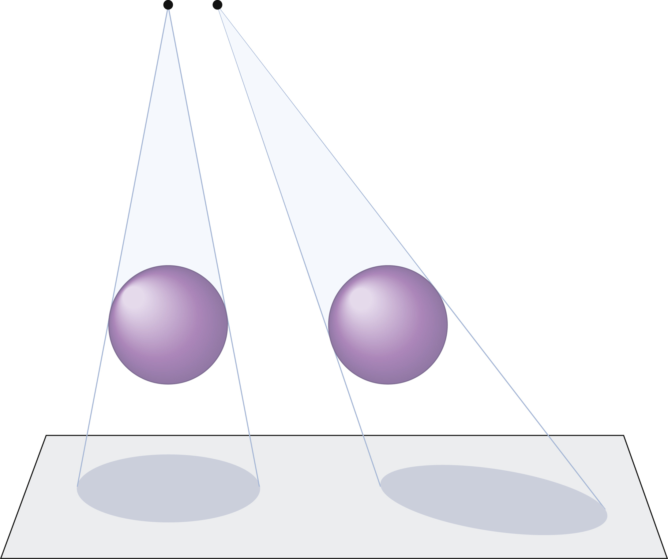
When the central ray is angled, the relationships among the beam, part, and IR are altered. A sphere that is imaged by a straight perpendicular beam is represented as a circular image. An image of the same sphere, when imaged by an angled beam, appears as an oval. Objects may appear to be elongated or foreshortened (Fig. 7.14).
Because the structures of the body do not lie in exact 90-degree perpendicular relationships to one another, central ray angulation is used in many radiographic examinations to help demonstrate specific anatomic details.
Changing the orientation of the body part undergoing radiography also affects the relationship of the beam, object, and IR. If the object of interest is superimposed on another object, the resulting image is difficult to evaluate. By rotating or obliquing the body, the object of interest can be projected free from the interference of the overlying object. Frequently, a combination of part rotation and central ray angulation is used to best demonstrate the anatomic details free from superimposition by overlying structures (Fig. 7.15). Ideally, the goal of a radiologic technologist is to place the anatomic part parallel to the IR and have the central ray aligned perpendicular to the IR.

Fluoroscopic Imaging
Fluoroscopic examinations often involve a combination of imaging processes. The fluoroscopic image itself is a dynamic, or moving, image rather than a static radiographic image. An analogy is that of a movie compared with a snapshot.
The fluoroscopic examination is usually divided into two portions: (1) viewing a physiologic event in real time (as it occurs) and (2) archiving images for later review. Modern fluoroscopic units are constructed so that the x-ray tube may be located either over or under the x-ray table. Opposite the tube is the image intensifier unit or the flat-panel detector (FPD), a device that intercepts the attenuated beam as it exits the patient. The image intensifier or an FPD is the actual IR in this case, rather than the IRs previously described. When the x-ray photons reach the image intensifier or the FPD, they are transformed into an electronic image. This image is then displayed on a television monitor for viewing. The radiologist is able to view a physiologic event (e.g., the passage of barium compound through the stomach) and observe abnormalities in function.
While observing the dynamic image, the radiologist frequently wishes to preserve an image as a record of the dynamic examination. A variety of image-archiving methods are available. Spot imaging is a common method of achieving this end. For spot images, the fluoroscopic unit changes instantaneously to radiographic mode for the duration of the exposure. These spot images are then processed, viewed, and stored, as with any other image. Digital fluoroscopy is replacing traditional filming and allowing for easy manipulation of the fluoroscopic images after they have been converted to a digital signal.
Summary
- • Capturing the image produced by x-rays in a format allowing for storage and repeated viewing has become the task of the radiologic technologist. The basic mechanism of x-ray production has not changed a great deal. A beam of x-rays, mechanically produced by passing high voltage through a cathode ray tube, traverses a patient and is partially absorbed in the process. A device called an IR intercepts the x-ray photons that are able to exit the patient. Various different IR systems are used in radiography, including film-screen systems, CR and DR systems (cassette-based and cassette-less), and fluoroscopic imaging systems.
- • An image of good quality must possess a proper balance of photographic properties (IR exposure and contrast) and geometric properties (spatial resolution and distortion). Of the many factors contributing to image quality, the radiographer must be able to manipulate technical factors such as mAs, kVp, and SID; choose and operate appropriate imaging equipment and accessories; and use proper positioning and patient care skills to obtain high-quality diagnostic images.