Equine and Large Animal Radiography*
Marg Brown RVT, BEd Ad Ed
The essential joy of being with horses is that it brings us in contact with the rare elements of grace, beauty, spirit, and fire.
—Sharon Ralls Lemons, Author and equestrian
- 1. Understand the terminology used in equine and large-animal radiography.
- 2. Identify skeletal anatomy.
- 3. Produce a diagnostic radiograph for common radiographic procedures of the equine/large-animal patient, using proper safety and positioning techniques.
- 4. Identify the less common views.
- 5. Identify normal equine and large-animal anatomy found on a radiograph.
Key Terms
Key terms are defined in the Glossary on the Evolve website.
Caudoproximal-craniodistal (CdPr-CrDi)
Cranioproximal-caudodistal (CrPr-CdDi)
Crena
Dorsolateral-palmaromedial oblique (DLPMO)
Dorsolateral-ventrolateral oblique (DLVLO)
Dorsomedial-palmarolateral oblique (DMPLO)
Dorsoproximal-dorsodistal oblique (DPr-DDi)
Dorsoproximal-palmarodistal (DPr-PaDi)
Flexor view
High coronary view
Lateromedial (LaM)
Midsagittal plane
Occlusal
Palmaroproximal-palmarodistal oblique (PaPr-PaDi)
Plantaroproximal-plantarodistal (PlPr-PlDi)
Positional terminology
Skyline
Sulcus
Tangential
Ungular or collateral cartilages
Upright pedal route
Ventrolateral-dorsolateral oblique
Weight bearing
Technical Note:
To preserve space, the radiographs presented in this chapter do not show collimation. For safety, always collimate so that the beam is limited to within the image receptor edges. In film radiography, you should see a clear border of collimation (frame) on every radiograph. In some jurisdictions, evidence of collimation is required by law.
Imaging large animals requires good planning, good teamwork, lots of patience, and being prepared to expect the unexpected. The common principles of radiography that apply to small animals also apply to large animals, with the major differences being due to patient size and posture, which necessitate special consideration for areas of patient restraint, equipment, preparation, radiation safety, and positioning devices. Safety of personnel and patient is critical.
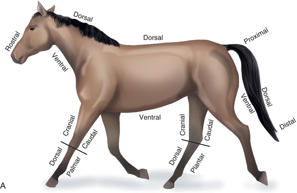
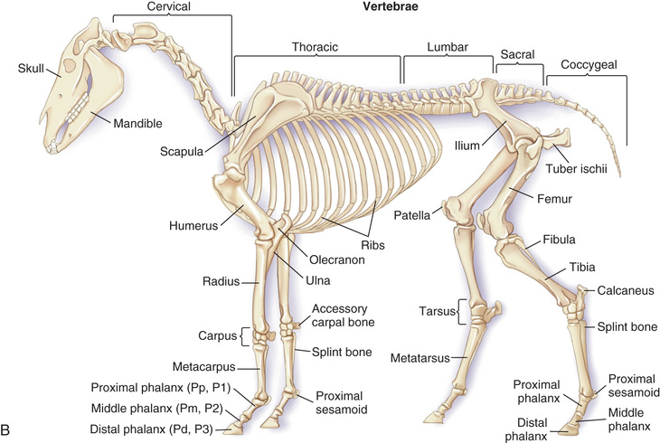
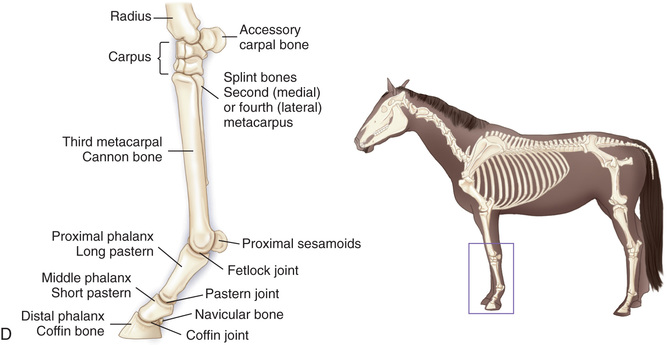
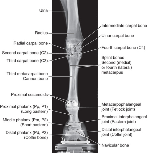
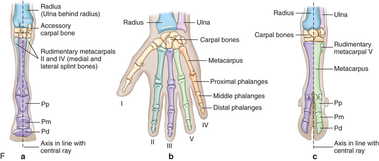
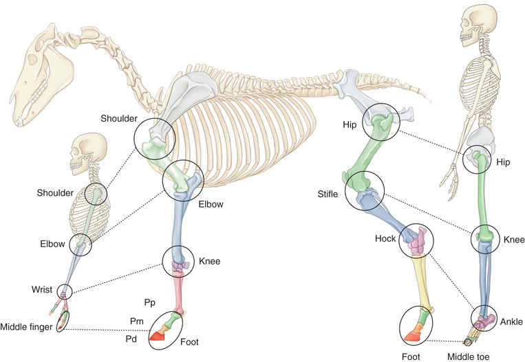
Compare the large-animal anatomy with human and small-animal anatomy (Fig. 24.1). The technical terms are similar but common terms differ.
Special Considerations
Restraint and Patient Preparation
Large animals in the standing position are minimally restrained, which is a concern for both human and machine safety. Large animals can easily become startled when confronted with unfamiliar objects, so it is important to minimize sudden movements and loud noises. Keep the behavior of the particular patient in mind, and modify your restraint to take advantage of that behavior, being aware that any sights or sounds such as uncoiling electrical cords or moving positioning devices can startle a typically quiet horse.
Ensure there is a solid ground surface that is level, clean, and nonslippery. The area should be quiet, free of obstacles, and large enough for personnel to move around the horse safely. Sedation may calm the patient and curtail startling that can cause movement blur on the image. Depending on the patient, consider various strategies such as raising the opposite limb, using a twitch, offering food, or using stocks. A competent handler is essential if the horse is being difficult or sedation is not an option.
Movement artifacts, poor positioning of the patient or the x-ray beam, and inadequate exposure are the most common reasons that images must be repeated. Among other inconveniences, any repetition means further radiation dose for the restrainer or the patient. To help minimize repeat radiographs, take the time to make sure that the patient is properly positioned, the image receptor is properly placed, and the central ray is directed correctly.
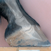
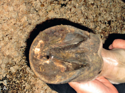
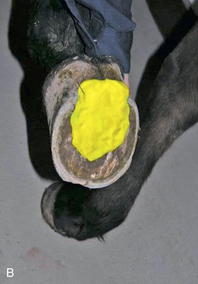
Proper patient preparation is essential to obtain high-quality radiographs and to minimize radiation exposure. The hair coat should be dry, brushed, and cleared of dirt or other debris. If the foot is being radiographed, it is important to prevent overlying shadows superimposed on the field of view. This is especially true of dorsopalmar/dorsoplantar and oblique views. Remove the shoe and trim back any overgrown portions of the foot. Pick and thoroughly clean the sole and clefts, and then pack the sulci adjacent to and in the center of the frog with a substance of similar radiographic opacity, such as Play-Doh, methylcellulose, or softened soap, to eliminate gas shadows due to the grooves of the frog (Fig. 24.2).
Double-check that you have all proper equipment and supplies with you, including foot blocks, as well as protective equipment and devices for all personnel to be as far from the primary beam as possible. If film cassettes are used and radiographs are being taken off site, make sure to take enough cassettes and film to the facility to allow for “repeats” and unexpected views. For digital radiography make sure that all required equipment such as spare cords, hand switches, or required batteries is on hand.
 Technician Notes
Debris such as shavings, mud, sand, small stones, and manure may cause radiographic artifacts. Sweep the area you are working in to keep the packing clean and minimize artifacts. Visually inspect and clean the legs and hooves well before taking images of the area. Depending on the size of the foot, try brown paper bags, craft paper, sandwich bags, plastic wrap, paper towel, or dry gauze to keep the packing material from picking up particles.
Radiation Safety and Positioning Devices
All of the radiation safety principles applied to small animals equally apply to large animals. When working with large animals, concern for physical safety often supersedes radiation safety. Thus it is essential to constantly keep the three tenets of radiation safety in mind (shielding, distance, and time).
Portable machines can be particularly dangerous with regard to radiation exposure as they can be aimed in any direction and they use longer exposure times than stationary units to produce diagnostic images due to limited machine power. It is critical for all individuals who will be in the path of the beam, near the beam, or holding the portable x-ray unit to have appropriate and proper fitting protective lead attire, thyroid collars, and a monitoring badge (see Chapter 3).
All personal protective equipment (PPE) must undergo a routine maintenance schedule to evaluate weaknesses and breakage (see Chapters 3 and 9). Proper storage of PPE is important; avoid folding gowns and gloves.
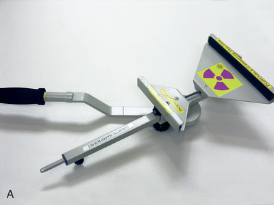
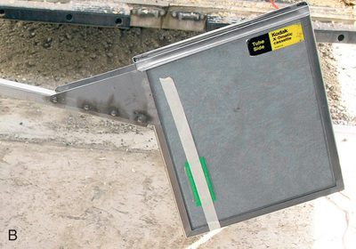
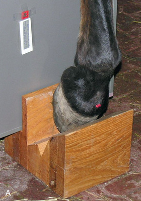
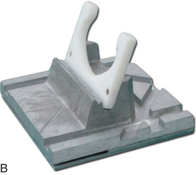
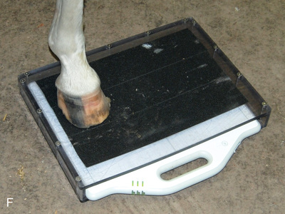
The most significant safety action is to increase one's distance from the primary beam through the use of a cassette holder (Fig. 24.3) and the use of a tripod to hold the x-ray unit if space and circumstances allow. Because the construction of x-ray machines does not allow the primary beam to be centered less than about 10 cm (4 inches) from the ground, a positioning block is needed to raise the affected foot (Fig. 24.4) for most views of the foot and pastern.
Always collimate. The primary beam should only include the area of interest so that all margins of the primary beam are visible on the processed film. In digital imaging the algorithm depends on proper collimation. Stand out of direct or bright light to see the collimator guide-light. Because the horizontal beam is standard, always be conscious of where the beam is directed and where individuals are standing; a cassette holder should be used when possible. To help decrease exposure time, use a fast combination of film and screen if using this system.
The source-image distance (SID) is generally less for large animals, with the common SID being 26 to 30 inches (66 cm-76.2 cm), compared with 40 inches (100 cm) in radiography of small animals. Always use the retractable tape measure to determine the proper SID based on the technique chart. Do not guess! Some units have two small laser pointers at precise angles that merge at the correct distance when the collimator light is on. A shorter SID also helps decrease the exposure time. If the SID changes from what is suggested on the technique chart, keep this formula in mind to change the mAs:
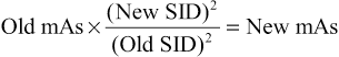
Review Chapters 5 and 6 if you need to adjust the image technique.
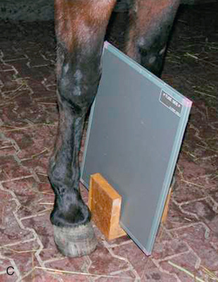
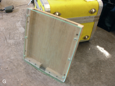
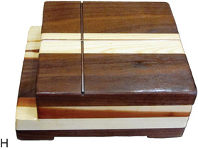
A cassette tunnel is also useful for digit radiographs to protect the image receptor for dorsopalmar/dorsoplantar and oblique views of the foot. A cassette tunnel can be purchased or can be manufactured out of radiolucent wood (avoid use of nails) or hard plastic durable enough to withstand the weight of the horse. If using a cassette tunnel, make sure it is strong enough to support the weight of the horse and is translucent to minimize artifacts on the film (Fig. 24.4F and G). To minimize a slippery surface, cover with duct tape or use a mouse pad or section of yoga mat between the hoof and tunnel.
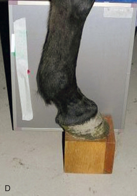
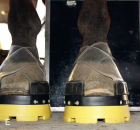
If using a foot block, have it high enough so that the beam can be directed in a horizontal plane on the area of interest. Ideally, the block should have a slot to support the cassette close to the limb to minimize distortion (Fig. 24.4D). If only the lateromedial view of the digit is needed, then shoe removal, sole cleaning, and foot trimming are not essential. For equal weight-bearing, both front feet should be on a foot block. If only the affected foot is placed on the block, improper pressure of the distal limb joints may affect the accuracy of the diagnosis.
The opposite limb may need to be lifted to ensure full weight-bearing and to prevent motion if equal weight-bearing is not required.
Keep the image receptor as close and parallel to the limb as possible to minimize object-film distance (OFD) and distortion. The suggested angle with the ground may change depending on the limb confirmation of the patient. The central ray should always be perpendicular to the limb axis being radiographed.
Technician Notes
ALWAYS keep the three principles of radiation safety in mind—time, distance, and shielding—when imaging large animals. Also remember to collimate, collimate, collimate.
Equipment
Of the three types of x-ray machines available—portable, mobile, and ceiling mounted—the portable unit is the most practical for those in ambulatory practices. Portable units are small and can be set up wherever there is a power supply.
Ensure there is an adequate power supply, as line voltage may vary, causing inconsistency in the exposures. These units are generally adequate for radiography of the equine distal limbs, skull, and cranial cervical vertebrae. Keep cords well away from feet to prevent tangling or damage from being stepped on. Position the horse so the cords can reach both the left and right sides. Although the portable equipment is built to withstand a certain amount of rough handling, transportation and frequent movement of radiographic equipment increase the opportunity for damage to x-ray equipment. Units should never be left in the vehicle overnight during below-freezing temperatures unless a sufficient warm-up time is taken into consideration before the first exposure.
Depending on the type of unit, the kilovoltage (kV) and milliampere (mA) are generally preset, giving power anywhere from 40 to 120 kV and 15 to 100 mA. Time is usually the variable control, providing values of 0.3 to generally 50 milliampere-seconds (mAs). Newer units have variable kV and mAs. The digital displays allow adjustments of 1- to 5- kV increments. Because of the relatively low mA capacity, movement is a concern. Mobile units can be wheeled from room to room in the same premises, but are generally too cumbersome to be easily moved and transported. The kV and mA capacity is higher, allowing for shorter exposure times and less chance of motion artifacts than with the portable units.
Veterinary specialty referral practices commonly use large units permanently mounted on a set of ceiling rails to allow horizontal and vertical movement. These high-capacity units have the greatest output range (between 800 and 1000 mA), capable of obtaining high-quality radiographs of regions such as the thorax, pelvis, and thoracolumbar vertebrae. It may be difficult to obtain parallel views of the feet because the unit may not reach the ground close enough to prevent obliquity. A supplementary portable unit is often used in these situations.
Exposure factors vary for each machine, so contact the generator manufacturer for a technique chart that can be used as a starting point. See Chapters 5 and 8 for suggested equine charts.
Regular maintenance and calibration of all x-ray units are essential to the consistent production of quality radiographs and maintenance of a safe working environment. Inspections should be implemented as per local regulations.
See Chapter 8 for further information on digital equipment.
Technician Notes
Electrical power may vary in different barn settings. Power may not have the consistency (brownouts) to produce quality radiographs. Have suitable and safety-approved extension cord(s) for exterior use as part of your equipment list. Proper-length cords are best (the shorter the better).
Equine Radiography
Radiographic Interpretation and Diagnosis
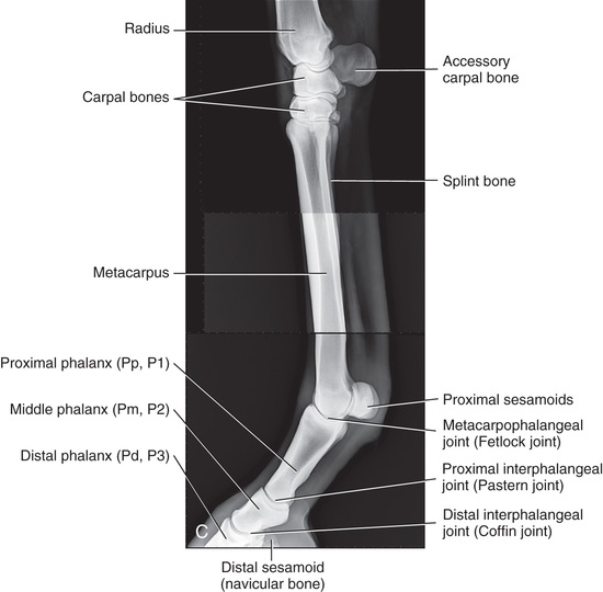
You should have an understanding of the normal equine anatomy. Use a systematic approach, making sure to view the whole image. Review the radiography checklist found in Chapter 15.
The purpose of most radiographs taken in equine practice is to evaluate the bones of the skeleton; thus any response of the bone to insult or disease is relevant. Any changes such as sclerosis (causing more of a radiopaque image) or demineralization (radiolucent appearance) may not be visible on the radiograph, as a change of at least 30% in the bone mineral matrix is required before radiographic changes are evident.1
Consideration may need to be given to additional imaging for accurate diagnosis and prognosis. This would include ultrasonography as well as cross-sectional imaging modalities such as computerized tomography (CT), magnetic resonance imaging (MRI), scintigraphy, and further diagnostic testing. CT and MRI show the most detail in all structures, indicating actual soft tissue and cartilage within the foot. Modalities such as nuclear scintigraphy and thermography show problem areas to the bone and soft tissue, such as ligaments, tendons, and articular cartilage that are poorly imaged on radiographs (see Fig. 24.64).
Prepurchase Examinations
Equine clients often request a prepurchase examination of a horse before buying a competitive or breeding prospect. This examination is done to reduce the buyer's risk and assess the current health and athletic soundness of the horse. The examination is not a guarantee of the health or soundness of the horse, but an interpretation of the ability of the horse to meet the intended purpose of the procurer. Depending on the level of expected performance or value of the purchase, this examination may include extensive radiographs.
It is critical for all parties to identify any potential conflict of interest that may exist. The veterinarian requested to perform such an examination must clearly identify his or her relationship with, or prior knowledge of, the horse to be purchased and its owners or trainers. It is recommended to have a legal agreement prepared and signed that clearly identifies any relationship or knowledge to protect the interest of the performing veterinarian.
Technician Notes
Unless otherwise indicated, when the limb is described in this chapter, the forelimb terminology is used, but it is understood that the same principles apply to the hind limb.
Labeling and Terminology
For proper diagnosis and legal requirements, correct labeling is mandatory. As with radiography of small animals, permanent identification of the patient and owner (or purchaser for a prepurchase examination) is required. The specific limb being radiographed should also be identified, as well as the actual position. This includes indicating forelimbs and hind limbs, especially distal to the carpus/tarsus.
As in small-animal radiography, the proximal end of the extremity is at the top of the viewer for DP/PD/CrCd/CdCr views. For the lateral or oblique radiographs, the proximal end points up, and the cranial or dorsal aspect of the limb is to your left.
Conventionally, limb markers should be placed dorsally or laterally. Place directional markers (right/left, front/rear) on the lateral aspect of the limb for DP(CrCd) and oblique views and at the dorsal/cranial aspect for lateromedial views. Use Velcro tabs or duct tape to affix to plate. If there is a swelling on the limb, a marker such as a BB pellet taped on the skin might be useful. If using a digital plate, take images in the order of DP, DLPMO, DMPLO, and LM to move the markers only once.
Because equine skeletal structures are large and complex, multiple views are required. In small animals, generally two views perpendicular to each other are taken. Horses generally require a minimum of four views for most positions, and six for many joints.
Refer to Chapter 15 for a review of some of the basic terminology.
Technician Notes
Here is a short review of the terms you should be familiar with especially in reference to large animals (see Fig. 24.1):
- • Dorsal, palmar and plantar, cranial, and caudal: Remember these terms take precedence when combined with other terms.
- • Describe radiographic projections from the point of entrance of the beam to the point of beam exit.
- • Technically a lateromedial limb view should be termed medial if applying the rules, but this is an exception and the view is commonly referred to as lateral.
- • Terminology of the limbs proximal to the tarsus and carpus: Cranial (the part of the body facing the head) or caudal (the part of the body facing the tail).
- • Distal to and including the carpus and tarsus: The terms are dorsal (the part of the body facing the head) and palmar (front limb facing the tail) or plantar (hind limb facing the tail).
- • Oblique: Not parallel to one of the two major directional axes (Fig. 24.5).
- • Tangential or skyline: Refers to the central ray entering and exiting the same side of the limb so that the bone is in profile.
- • In those views requiring a combination of directional terms: A hyphen should be inserted to separate the point of entry and point of exit. Example: palmaroproximal-palmarodistal (PaPr-PaDi).
Technician Notes
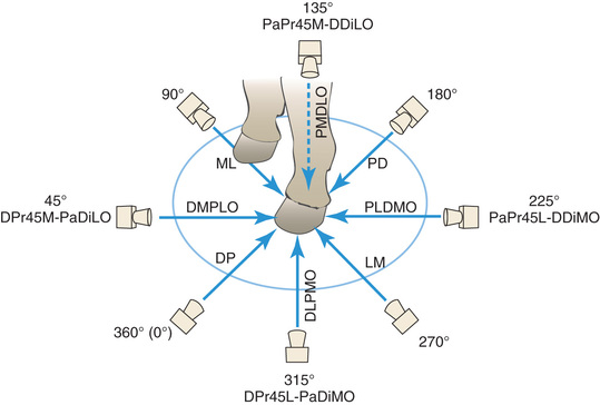
The lateromedial and dorsopalmar (plantar) views evaluate only 50% of the limb. Further views are required for proper diagnosis. These views are known as oblique views and are obtained with the radiographic beam at an angle to the midsagittal plane of the limb (between dorsal and lateral/medial).
Dorsolateral-Palmaromedial Oblique (DLPMO)
For the dorsolateral-palmaromedial oblique (DLPMO) view (Fig. 24.6B), the central ray faces the dorsal part of the limb aimed 45 degrees laterally from the midline. The image receptor is on the palmaromedial aspect of the limb so that it is perpendicular to the beam. Remember “point of entry to point of exit”; the beam travels from dorsolateral to palmaromedial. The film marker is placed along the lateral aspect of the image receptor. So that there is no confusion as to what angle should be used, the proper description for this 45-degree DLPMO view is dorsoproximal 45-degree lateral palmarodistomedial oblique (DPr45L-PaDiMO).
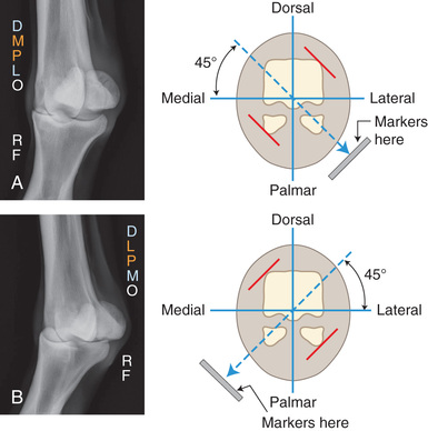
What is actually being highlighted on this DLPMO projection (Fig. 24.6B) is the portion that is not against the film—specifically the lateral sesamoid in Fig. 24.6B. Note that because this is taken at an oblique angle, the image of the medial proximal sesamoid is obstructed by the distal metacarpus (see Technician Notes). Thus an oblique projection allows the portion of the bone farther from the film to be in profile. The radiograph is like a shadow: the way the beam is directed, the body part on the film is superimposed in the oblique, and the opposite edges are highlighted.
The view is correctly described first from where the beam enters on the limb and then where it exits. Using point of entry to point of exit the DLPMO is technically termed a medial oblique because the beam enters off the midline on the lateral aspect and exits on the medial aspect. The medial aspect is against the film. However, because the lateral portion of the bone is in profile in a DLPMO, practicing veterinarians may refer to the position as a lateral oblique.
Technician Notes
To help remember which views are highlighted in the oblique views, look at the abbreviation for the view and ignore the “O.” Take the middle two letters and then the outer two letters. In the case of DLPMO, the middle two letters are (LP) and the outer two letters are (DM). So you are looking at the dorsomedial and lateropalmar surfaces of the bone (the red lines in Fig. 24.6B). Because of the angle of the beam, the lateral portion, not the medial aspect, is more in profile. The medial portion is hidden.
Dorsomedial-Palmarolateral Oblique (DMPLO)
The same principle applies to the dorsomedial-palmarolateral oblique (DMPLO) (Fig. 24.6A), but this time the central ray is aimed at the dorsal part of the limb 45 degrees medially to the midline. The image receptor is on the palmarolateral aspect of the limb and is perpendicular to the beam. The beam travels from dorsomedial (point of entry) to palmarolateral (point of exit). The film marker is placed along the lateral aspect of the image receptor, appearing to be on the dorsal part of the limb in the radiograph. So that there is no confusion as to what angle should be used, the proper description for this 45-degree DMPLO is dorsoproximal 45-degree medial–palmarodistolateral oblique (DPr45M-PaDiLO).
Taking the two middle and two outer letters once the “O” is removed tells us that the dorsolateral and mediopalmar surfaces (red lines on Fig. 24.6A) will be highlighted. The medial proximal sesamoid is in profile.
Remember the view is correctly described first from where the beam enters on the limb and then where it exits. Using point of entry to point of exit, the DMPLO is technically termed a lateral oblique since the beam enters off the midline on the medial aspect and exits on the lateral aspect. The lateral aspect is against the film. However, because the medial portion of the bone is in profile in a DMPLO, practicing veterinarians may refer to the position as a medial oblique.
In practice, you may hear common terms that are used in place of the correct anatomical terms (Table 24.1) or different modes of describing the beam. Anterior posterior (AP), a human term, is still sometimes used in practice; however, the correct nomenclature is dorsopalmar or dorsoplantar (DP). Common terms are listed here for the purpose of further understanding but are not necessarily the proper nomenclature.
TABLE 24.1
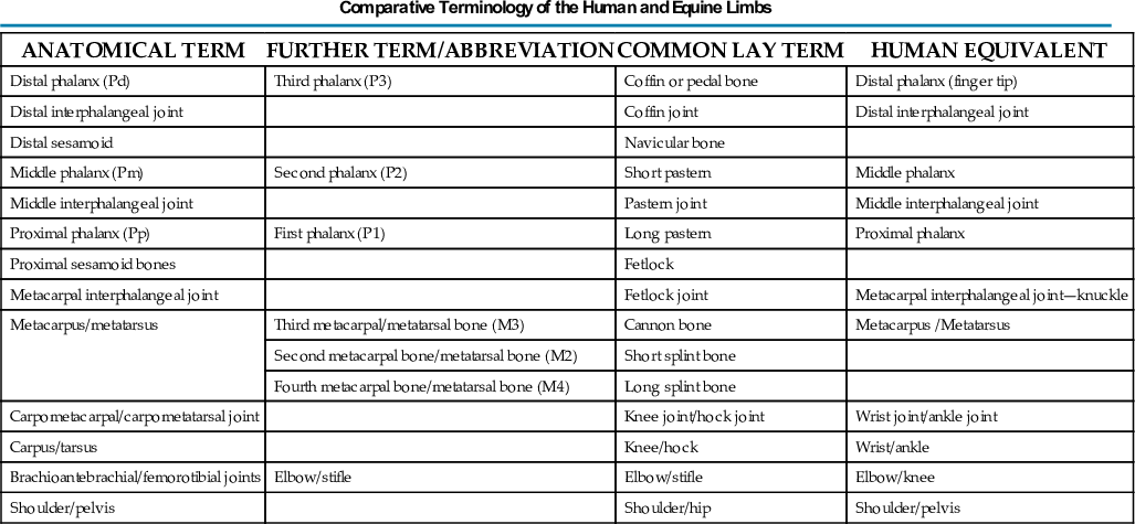
Data from Butler JA, Coles CM, Dyson SJ, et al: Clinical Radiology of the Horse, Osney Mead, Oxford, 1993, Blackwell Science Ltd; Morgan JP: Techniques of Veterinary Radiography, Ames, IA, 1993, Iowa State University Press; Thrall DE: Textbook of Veterinary Diagnostic Radiology, St Louis, 2007, Saunders; Weaver M, Barakzai S: Handbook of Equine Radiography, London, 2010, Saunders.
Technician Notes
To demonstrate that the opposite projections will be in profile, tape two different objects, such as a pen and pencil, to an empty paper towel roll. Label four sides dorsal, palmar, lateral, and medial, and place a piece of paper behind your “limb.” Use your finger as the x-ray beam and try the oblique views. Notice that the opposite protrusion is in profile. Using a flashlight may also help you visualize the projections better. The radiograph is like a shadow with the way the beam is directed—the part on the film is superimposed, but the opposite edges are highlighted.
Technician Notes
A human middle finger is equivalent to the front foot of the horse, whereas the hind foot is a human's middle toe (Fig. 24.7). Imagine standing on your middle toes all day. It is no wonder the foot is the most frequently imaged for equine lameness issues.
Equine Radiographic Positioning
Table 24.2 lists the views that are used in equine limb examination.
TABLE 24.2
| STRUCTURES EVALUATED/ COMMENTS | VIEWS/COMMENTSa | COMMON TERMINOLOGY |
|---|---|---|
| P3 | Dorsal 65-degree proximal–palmarodistal oblique (D65Pr-PaDiO); beam angled to ground, high coronary or upright pedal routes. Dorsoproximal-palmarodistal (DPr-PaDi) with horizontal beam | Dorsopalmar (DP) |
| Lateromedial (LM) with foot on block (optional). | Lateral (L) | |
| Oblique views especially if a P3 fracture is suspected: | ||
| (1) DLPMO | ||
| (2) DMPLO | ||
| Distal interphalangeal joint | Dorsal 65-degree proximal–palmarodistal oblique (D65Pr-PaDiO) high coronary route with beam angled to ground | Dorsopalmar (DP) |
| Lateromedial (LM) with foot on block to include solar margin of P3 and soft tissues of sole on the radiograph | Lateral (L) | |
| Optional views | Oblique views | |
| (1) DLPMO | ||
| (2) DMPLO | ||
| Navicular | Lateromedial (LM) | Lateral (L) |
Dorsoproximal-palmarodistal oblique (DPr-PaDiO): (1) High coronary stand-on route: 45 degrees: projects proximal border and extremities (D45Pr-PaDiO) 65 degrees: projects both borders and extremities (D65Pr-PaDiO) OR | Dorsopalmar (DP) | |
| Dorsopalmar (DP) | ||
| Palmaroproximal-palmarodistal oblique view (PaPr-PaDiO): | Flexor or skyline | |
| D65Pr45L-PaDiMO | DLPMO | |
| D65Pr45M-PaDiLO | DMPLO | |
| Pastern P1, proximal interphalangeal joint, P2 | Lateromedial (LM) | Lateral (L) |
| Dorsoproximal-palmarodistal oblique (D30-45Pr-PaDiO) | Dorsopalmar (DP) | |
| Dorsal 35-degree proximal, 35-degree lateral–palmarodistomedial oblique (D35Pr-35L-PaDiMO) | DLPMO | |
| Dorsal 35-degree proximal, 35-degree medial–palmarodistolateral oblique (D35Pr-35M-PaDiLO) | DMPLO | |
| Metacarpophalangeal/metatarsophalangeal joint/proximal sesamoid bones (fetlock) | Dorsal 10-degree proximal–palmarodistal oblique (D10Pr-PaDiO) | Dorsopalmar (DP) |
| Lateromedial (LM) extended | Lateral (L) | |
| Lateromedial (LM) flexed | Flexed lateral (L) | |
| Dorsoproximal 45-degree lateral–palmarodistomedial oblique (DPr45L-PaDiMO) | DLPMO | |
| Dorsoproximal 45-degree medial–palmarodistolateral oblique (DPr45M-PaDiLO) | DMPLO | |
| Optional views | Palmaroproximal-palmarodistal oblique view (PaPr-PaDiO) | Flexor/skyline/caudal tangential |
| Dorsoproximal-dorsodistal oblique (DPr-DDiO) | Extensor surface/skyline | |
| Metacarpal/metatarsal cannon bone (M3) | Dorsoproximal-palmarodistal (DPr-PaDi) | Dorsopalmar (DP) |
| Lateromedial (LM) | Lateral (L) | |
| Lateral splint bone (M4) | Dorsoproximal 45-degree lateral–palmarodistomedial oblique (DPr45L-PaDiMO) | DLPMO |
| Medial splint bone (M2) | Dorsoproximal 45-degree medial–palmarodistolateral oblique (DPr45M-PaDiLO) | DMPLO |
| Carpus | Dorsoproximal-palmarodistal (DPr-PaDi) | Dorsopalmar (DP) |
| Lateromedial extended (LM) | Lateral (L) | |
| Lateromedial flexed (LM) | Flexed lateral (L) | |
| Dorsoproximal 45-degree lateral–palmarodistomedial oblique (DPr45L-PaDiMO) | DLPMO | |
| Dorsoproximal 45-degree medial–palmarodistolateral oblique (DPr45M-PaDiLO) | DMPLO | |
| Optional views | Dorsoproximal-dorsodistal oblique flexed (DPr-DDiO) | Skyline |
| Tarsus | Dorsoproximal-plantarodistal (DPr-PlDi) | Dorsoplantar (DP) |
| Lateromedial (LM) extended | Lateral (L) | |
| Lateromedial flexed (LM) | Flexed lateral (L) | |
| Dorsoproximal 45-degree lateral–plantarodistomedial oblique (DPr45L-PlDiMO) | DLPMO | |
| Dorsoproximal 45-degree medial–plantarodistolateral oblique (DPr45M-PlDiLO) | DMPLO | |
| Tuber calcaneus | Flexed plantaroproximal-plantarodistal (PlPr-PlDi) | Skyline |
| Radius | Cranioproximal-caudodistal (CrPr-CdDi) | Craniocaudal (CrCd) |
| Lateromedial (LM) | Lateral (L) | |
| Optional views | Caudoproximal-craniodistal (CdPr-CrDi) | Caudocranial (CdCr) |
| Cranioproximolateral-caudodistomedial oblique (CrPrL-CdDiMO) | CrLCdMO | |
| Cranioproximomedial-caudodistolateral oblique (CrPrM-CdDiLO) | CrMCdLO | |
| Elbow joint | Cranioproximal-caudodistal (CrPr-CdDi)—standing | Craniocaudal (CrCd) |
| Mediolateral standing (ML) | Lateral (L) | |
| Optional views | Cranioproximal-craniodistal oblique (CrPr-CrDiO) of olecranon | Skyline or flexor |
| Lateromedial (LM) | Lateral (L) | |
| Mediolateral through the thoracic cavity | Mediolateral (ML) | |
| Cranioproximal-caudodistal (CrPr-CdDi)—recumbent | Craniocaudal (CrCd) | |
| Mediolateral (recumbent) (ML) | Lateral (L) | |
| Craniomedial-caudolateral oblique | CrMCdLO | |
Shoulder Optional views | Mediolateral (ML) | Lateral (L) |
| Cranioproximal 45-degree medial–caudodistolateral oblique (CrPr45M-CaDiLO) | CrMCdLO | |
| Cranioproximal 45-degree lateral–caudodistomedial oblique (CrPr45L-CaDiMO) | CrLCdMO | |
| Stifle | Lateromedial (LM) | Lateral (L) |
| Caudoproximal-craniodistal (CdPr-CrDi) | Caudocranial (CdCr) | |
| Lateral trochlear ridge and medial femoral condyle (stifle) | Caudoproximal 60-degree lateral–craniodistomedial oblique (Cd60L-CrMO) | CdLCrMO |
| Optional stifle | Cranioproximal-caudodistal (CrPr-CdDi) | Craniocaudal (CrCd) |
| Cranioproximal-craniodistal oblique(CrPr-CrDiO) | Skyline patella | |
| Lateromedial flexed (LM) | Flexed lateral (L) |
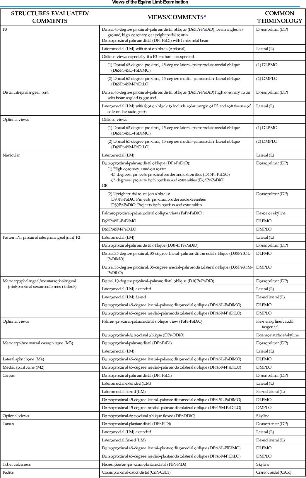
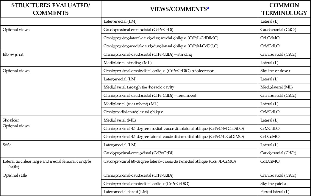
aPalmar is used in this chart and chapter with the understanding that plantar can be substituted when referring to the hind limb.
Data from Weaver M, Barakzai S: Handbook of equine radiography, London, 2010, Saunders Elsevier; Morgan JP: Techniques of veterinary radiography. Ames, IA, 1993, Iowa State University Press; Butler JA, Coles CM, Dyson SJ, et al: Clinical radiology of the horse, Osney Mead, Oxford, 2008, Wiley-Blackwell; Thrall DE: Textbook of veterinary diagnostic radiology, ed 6, St. Louis, 2013, Elsevier.
Technician Notes
Keep the principles of good radiographic imaging in mind every time. The body part should be close to and parallel to the image receptor, and the central ray is perpendicular to both. Think radiation safety for each exposure.
The Digit (Foot)
The distal phalanx and the navicular bone comprise the digit or foot. Common indications for imaging the equine foot include localized lameness by clinical examination (pain on pressure from foot testers, increased digital pulses, etc.) or by diagnostic analgesia, laminitis, penetrating wounds, or as required for a prepurchase examination.1
Dorsopalmar (DP): Dorsoproximal-Palmarodistal View of the Digit
The three following views can be taken for the dorsoproximal-palmarodistal (DPr-PaDi) views of the foot. The terminology changes slightly depending on the actual positioning. Because the foot or the beam is at an angle to the ground, the high coronary and upright pedal routes are technically termed DPr-PaDiO views. Note that there is no lateral or medial distinction, so do not get confused.
- High coronary view: Dorsal 65-degree proximal–palmarodistal oblique (D65Pr-PaDiO).
- • The beam is angled to the ground 65 degrees dorsoproximal (stand-on route) (see Fig. 24.8).
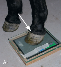
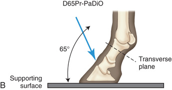
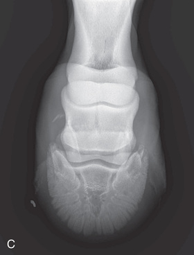
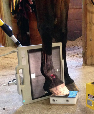
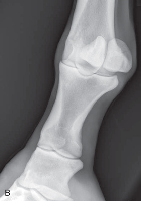
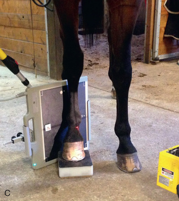
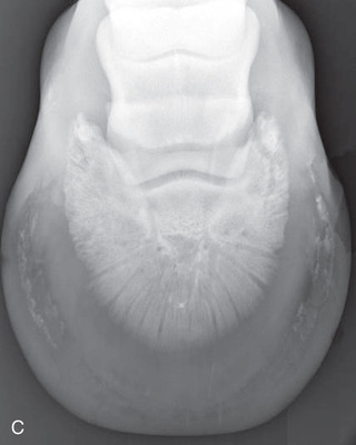 FIG. 24.8 A, Positioning for the dorsoproximal (DP) view of the digit using a tunnel cassette for the high coronary stand-on view angled 65 degrees to the ground. The foot is best placed closer to the front of the cassette so that the foot shadow and thus relevant structures are included. B, Dorsoproximal-palmarodistal oblique (D65Pr-PaDiO) view of the equine distal phalanx and distal sesamoid bone (navicular) made at 65 degrees proximal to the supporting surface. This is often referred to as a DP, high coronary view. C, Radiograph of the dorsoproximal distal phalanx with the high coronary view route. (C courtesy Carolyn Bennet, Ontario Veterinary College, Veterinary Teaching Hospital, Diagnostic Imaging at University of Guelph, Ontario.)
 - • The foot is on top of the cassette tunnel, which is placed on the ground.
- • The foot is placed near the center and the toe close to the front edge of the tunnel.
- • This view tends to be most common
- • The beam is angled to the ground 65 degrees dorsoproximal (stand-on route) (see Fig. 24.8).
- Upright pedal route: Dorsoproximal-palmarodistal oblique (DPr-PaDiO).
- • The beam is horizontal and parallel to the ground with the toe pointed down (Fig. 24.9).
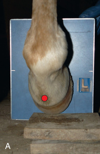
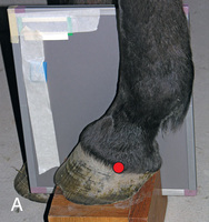
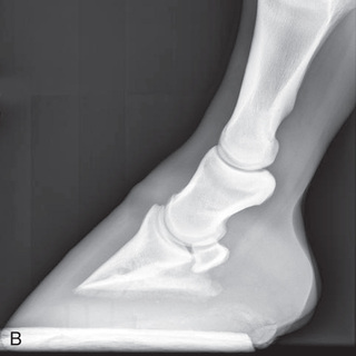
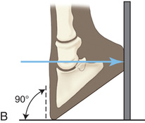
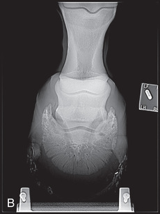 FIG. 24.9 A, Positioning for the dorsoproximal (DP) digit and the navicular bone using the upright pedal position. The beam is horizontal and parallel to the ground. Referred to as the dorsal 65-degree proximal–palmarodistal oblique (D65Pr-PaDiO). B, Radiograph of the dorsoproximal distal phalanx with the upright pedal position. (A courtesy Shannon Brownrigg; B courtesy Stacey Thompson, BSc, RVT, McKee-Pownall Equine Services.)
 - • Point the toe of the foot downward so it is resting on a block, or use a navicular block.
- • The sole is perpendicular to the ground, and the dorsal hoof wall is 65 degrees to the horizontal for the coffin bone.
- • A positioning block with a slot (see Fig. 24.4A) or the Redden Navicular Block (Fig. 24.4B) can be used so that the hoof angle is 65 degrees.
- • The beam is horizontal and parallel to the ground with the toe pointed down (Fig. 24.9).
- Position 3: True dorsopalmar view (Fig. 24.10).
- • The beam is horizontal and parallel to the ground, with the foot being weight-bearing.
- • The foot is placed on the foot block to raise it to the level of the x-ray tube.
- • The image receptor is positioned vertically for the true DP and directly caudal to the foot on the ground or in the cassette holder groove.
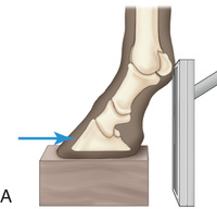
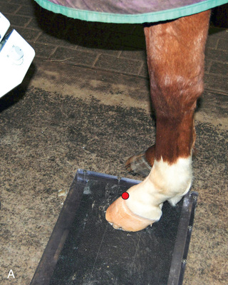
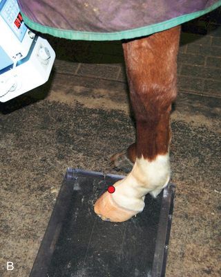
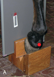
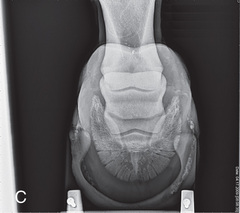
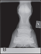 FIG. 24.10 A, Positioning of the foot on a foot block to obtain a weight-bearing DP view of the digit. B, Radiograph of the true dorsopalmar view with the foot on a block. (Courtesy Stacey Thompson, BSc, RVT, McKee-Pownall Equine Services.)
For all 3 positions:- Central Ray: On the midsagittal plane (MSP) of the pedal bone (dorsal foot wall) 2 cm above the dorsal coronary band.
- Include: The full digit—foot wall, pedal bone, superimposed navicular bone, middle phalanx (P2), and the distal part of the proximal phalanx (P1).
- Collimate: To include area of interest, ensuring that labels are included and borders are visible.
- High coronary view: Dorsal 65-degree proximal–palmarodistal oblique (D65Pr-PaDiO).
Comments
- • Aim the central ray at right angles to the correctly trimmed foot wall.
- • When the beam is at an angle to the ground or to the limb, the view is technically called a DP oblique (note there is no mention of medial or lateral so the beam is on the MSP).
- • Lift the opposite limb for restraint for the high coronary view.
- • Proper full preparation of the sole is essential.
- • Wings of the coffin bone and distal sesamoids should be equidistant.
- • Increase the mAs to view the navicular bone, and decrease the mAs for the solar margin.
- • The purpose of the high coronary study is to note the number, size, and character of the vascular channels. The crena, which is the large notch in the solar border; the palmar processes, or wings formed by the solar border; and the ungular or collateral cartilages are all noted.2 This is the preferred view for the interphalangeal joint.
- • The upright pedal route better shows the extensor process, conformation, quality of hoof care, and relationship of foot to the surface and is preferred for the bones.1,2
- • The true DP with the foot weight-bearing on a block and the beam parallel to the ground is slightly more limited than the high coronary view, but does assess lateromedial foot imbalance, some distal phalanx fractures, and ossification of the collateral cartilages of P3.1,2
- • These views also apply to the hind limb, with the term plantar being substituted for palmar.
Technician Notes
The high coronary stand-on route literally means stand on the cassette tunnel. The upright pedal route has the pedal bone (digit) pointing downward, sole flat on the cassette and both perpendicular to the ground. In both of these cases the beam or the area of interest is at an angle to the ground.
Technician Notes
Do not get confused when you see the dorsoproximal-palmarodistal oblique view for the lower limb. This is called oblique because the central ray that is focused on the midsagittal plane is angled to the ground due to hoof conformation. There is no lateral or medial designation in these DP views, and the angle degree to the ground is placed right after the dorsal designation. The beam is always perpendicular to the area of interest.
Lateral: Lateromedial View of the Digit
The lateromedial view of the distal phalanx is used for all of the bones and joints of the foot.
- Patient: Is weight-bearing in a natural position.
- Place the Foot: On a block and the image receptor on the medial side of the leg in the positional slot of a block (Fig. 24.11).
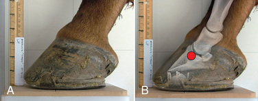
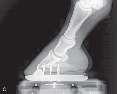 FIG. 24.11 A, Positioning for the lateromedial view of the distal phalanx. B, Radiographic anatomy of the lateromedial left equine distal phalanx. C, Radiograph of the lateromedial left equine distal phalanx of the above patient with the shoe in place. The shoe needs to be removed for other views of the digit. (C courtesy Vetel Diagnostics, San Luis Obispo, California; and Seth Wallach, DVM, DACVR, AAVR, Director and CEO of Veterinary Imaging Centre of San Diego.)
 - Central Ray: 90 degrees to the midsagittal plane of the foot wall, just below the coronary band so that the bulbs of the heel are visually superimposed.
- Beam: Should be parallel to the ground, midway between the dorsal foot wall and the bulbs of the heel.
- Include: The entire foot—whole foot wall, distal phalanx (P3), middle phalanx (P2), distal portion of P1, navicular bone, and distal interphalangeal and proximal interphalangeal joints.
- Collimate: To include area of interest, ensuring that labels are included and borders are visible.
Comments
- • The bulbs of the heel should be superimposed and in a straight line with the central ray.
- • Care must be taken when assessing the foot pastern axis, which may be altered if the horse is not fully weight-bearing on a level surface.3
- • Aim for a square stance unless the horse is painful or almost non–weight-bearing in which the affected foot can be pulled forward.
- • Wings of the coffin bone and distal sesamoids should be superimposed when viewing the radiograph.
- • Consider taping radiodense wire or a line of barium paste placed on the dorsal wall of the hoof, beginning at the coronet band and working down, to make it easier to visualize if there has been any rotation or sinking of P3 in laminitis. If using barium, always complete the other views before the barium is applied.
- • For this view of the distal phalanx, the purpose is to see the relationship between the dorsal foot wall and the dorsal border of the distal phalanx. The palmar processes may appear to be irregular with separate bony fragments. They are normally separated from the distal phalanx cartilages by a prominent parietal sulcus.2
- • This view also applies to the hind limb, with the term plantar being substituted for palmar.
Technician Notes
Minimizing obliquity is a concern for the lateral view, so it is important to make sure that the floor is level and the central ray is lined up so that the bulbs of the heel are superimposed.
Technician Notes
A common cause of nondiagnostic radiographs of the foot is lack of preparation. Artifacts need to be eliminated—remove the shoe; remove dirt, debris, and excess horny tissue; and pack the sulcus to eliminate air artifacts.
Technician Notes
The same principles apply to the hind limb. Substitute the term plantar for palmar.
Oblique Views of the Digit
Oblique views of the distal phalanx and navicular bone are as follows:
- DLPMO: Dorsal 65-degree proximal, 45-degree lateral–palmarodistomedial oblique (D65Pr45L-PaDiMO). The medial oblique aspect of the limb is against the film. The DLPMO view allows visualization of the lateral wing of the coffin bone. See Fig. 24.6B and Fig. 24.12.
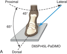
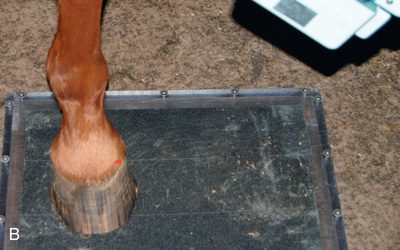
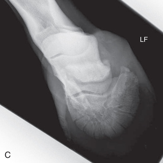 FIG. 24.12 A, A DLPMO view of the left equine distal phalanx made at 65 degrees proximal to the supporting surface and 45 degrees lateral to the dorsopalmar line or the midsagittal plane. The blue arrow indicates the side the beam is directed from. Specifically, this projection would be termed D65Pr45L-PaDiMO. B, Positioning for the DLPMO radiograph of the left front distal phalanx to view the lateral wing of the coffin bone. The beam is 65 degrees to the ground and 45 degrees lateral to the midsagittal plane. The foot is best placed closer to the side of the cassette facing the tube head to allow the full foot shadow to appear on the image. C, Radiograph of the DLPMO position of the digit as described in A and B. (B courtesy Dr. Usha Knabe, Knabe Equine Veterinary Services, Orangeville, Ontario; C courtesy Carolyn Bennet, Ontario Veterinary College, Veterinary Teaching Hospital, Diagnostic Imaging at University of Guelph, Ontario.)
 - DMPLO: Dorsal 65-degree proximal, 45-degree medial–palmarodistolateral oblique (D65Pr45M-PaDiLO). The lateral oblique aspect is against the film. The DMPLO view allows visualization of the medial wing of the coffin bone. See Fig. 24.6A and Fig. 24.13.
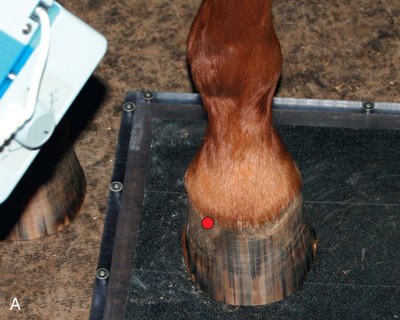
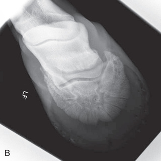 FIG. 24.13 A, Positioning for the DMPLO [D65Pr45M-PaDiLO] view of the left front distal phalanx. The beam is 65 degrees to the ground and 45 degrees medial to the midsagittal plane. Note placement of foot to ensure the full image will be shown. B, DMPLO radiograph of the distal phalanx to view the medial wing of the coffin bone. (A courtesy Dr. Usha Knabe, Knabe Equine Veterinary Services, Orangeville, Ontario; B courtesy Carolyn Bennet, Ontario Veterinary College, Veterinary Teaching Hospital, Diagnostic Imaging at University of Guelph, Ontario.)
- DLPMO: Dorsal 65-degree proximal, 45-degree lateral–palmarodistomedial oblique (D65Pr45L-PaDiMO). The medial oblique aspect of the limb is against the film. The DLPMO view allows visualization of the lateral wing of the coffin bone. See Fig. 24.6B and Fig. 24.12.
- Patient: Is weight-bearing.
- Foot: Is placed on the tunnel cassette with the foot off-center, slightly toward the side to be studied. The angle to be projected is closer to the edge of the image receptor.
- Beam: Angled 65 degrees on the dorsal surface downward on the DP line just below the coronary band and 45 degrees either lateral or medial to the midsagittal plane.
- Central Ray: Just distal to the coronary band, half the distance between the dorsal wall and the heels.
- Collimate: To include area of interest, ensuring that labels are included and borders are visible.
Comments
- • Keep the beam perpendicular to the foot axis; this is normally about 65 degrees to the ground (D65Pr).
- • Ensure that the foot is clean, the sole picked, and shoes have been removed.
- • The oblique views help detect nondisplaced fractures in the quarters of the solar border and in the plantar or palmar processes of the distal phalanx.
- • The DLPMO view visualizes the lateral wing of the coffin bone, which appears larger due to increased OFD. Because there is no superimposition, the lateral wing of the coffin bone appears grayer.
- • The DMPLO view visualizes the medial wing of the coffin bone, which appears larger due to increased OFD. Because there is no superimposition, the medial wing of the coffin bone appears grayer.
- • This positioning also applies to the hind limb, with the term plantar being substituted for palmar.
Technician Notes
As with small-animal imaging, plan so you minimize retakes. Your mental checklist includes but is not limited to the following: machine ready and settings correct, correct SID, PPE donned, use of a cassette holder or positioning device if possible, proper location of markers, patient properly prepared and restrained, correct body part and view, properly centered and borders included, and correct angle of the central ray so it is perpendicular to the body part and the image receptor.
Navicular Bone (Distal Sesamoid)
Lateral: Lateromedial View of the Navicular Bone
Positioning, Central Ray, and Collimation
Positioning, central ray, and collimation instructions are the same as those for the lateromedial view of the distal phalanx (Fig. 24.14).
Comments
- • This view assists in evaluating the changes in the shape of the bone that are often associated with chronic degenerative changes of navicular disease.1,2
- • If only a lateral view is required, the shoe does not have to be removed; only cleaning and brushing of the wall are required.
- • This view gives a foreshortened projection along the axis of the bone. Both borders and both surfaces will be projected in profile.
Technician Notes
If a radiodense wire is taped or barium paste is applied on the midsagittal plane of the dorsal hoof wall, it is easier to see the hoof wall axis on an image.
Dorsopalmar (DP): Dorsoproximal-Palmarodistal Oblique Views of the Navicular Bone
High Coronary Stand-on Routes
Dorsal 65-Degree Proximal–Palmarodistal Oblique (D65Pr-PaDiO) of the Navicular Bone
The D65Pr-PaDiO view projects both borders and extremities of the navicular, and the distal border can be seen through the distal and palmar (plantar) portions of the middle phalanx (Fig. 24.15).
- Patient: Is weight-bearing.
- Foot: Placed on the cassette tunnel, which is flat on the ground. Position the foot near the center and the toe close to the front edge of the tunnel.
- Beam: 65 degrees with the ground and at 110 degrees with the hoof wall.
- Central Ray: On the midsagittal plane just distal to the coronary band centered between the bulbs of the heel, which are level.
- Include: All of P3, the navicular, and P2.
- Collimate: To include area of interest, ensuring that labels are included and borders are visible.
Dorsal 45-Degree Proximal–Palmarodistal Oblique (D45Pr-PaDiO) of the Navicular Bone
The D45Pr-PaDiO view projects the proximal border and extremities.
- Patient: Is weight-bearing.
- Foot: Placed on the cassette tunnel, which is flat on the ground. Position the foot near the center and the toe close to the front edge of the tunnel.
- Beam: 45 degrees with the ground and 90 degrees with the foot wall.
- Central Ray: On the midsagittal plane above the coronary band, centered between the bulbs of the heel.
- Include: All of P3, navicular, and P2.
- Collimate: To include area of interest, ensuring that labels are included and borders are visible.
Technician Notes
The 45-degree high coronary stand-on and the 90-degree upright pedal routes show the undistorted proximal navicular border.
The 65-degree high coronary stand-on and the 80-degree upright pedal routes show both the distal and proximal borders.
Upright Pedal Route of the Navicular Bone
Place the foot with the toe tipped so that the dorsal wall is positioned 80 degrees or 90 degrees from the horizontal for the navicular bone (Fig. 24.16).3
Dorsal 90-Degree Proximal-Palmarodistal Oblique (D90Pr-PaDiO) of the Navicular Bone
The D90Pr-PaDiO view projects the proximal border and extremities (equivalent to 45-degree high coronary view).
- Foot: Placed on a block with the toe pointing downward, the sole perpendicular to the ground, and the dorsal foot wall about 90 degrees to the horizontal.
- Use of Special Navicular Block: Place the foot in the slot closest to the front of the block or the 45-degree slot.
- Beam: Horizontal to the ground.
- Central Ray: Midsagittal plane just distal to the coronary band, centered between the bulbs of the heel.
- Include: All of P3, navicular, and P2.
- Collimate: To include area of interest, ensuring that labels are included and borders are visible.
Technician Notes
Be consistent when viewing a series of radiographs from the same patient so that the images are oriented in the same direction.
Dorsal 80-Degree Proximal–Palmarodistal (D80Pr-PaDiO) of the Navicular Bone
The D80Pr-PaDiO view projects both the proximal and distal borders and the extremities (equivalent to 65-degree high coronary view).
- Foot: Placed on a block with the toe pointing downward, the sole perpendicular to the ground, and the dorsal foot wall about 80 degrees with the ground.
- Use of a Special Navicular Block: Place the toe in the position closest to the image receptor or the 65-degree slot (Fig. 24.16).
- Beam: Horizontal and parallel to the ground.
- Central Ray: On the midsagittal plane 2 cm proximal to the coronary band between the bulbs of the heel.
- Include: All of P3, the navicular, and P2.
- Collimate: To include the area of interest, ensuring that labels are included and borders are visible.
Comments
- • Important: The foot needs to be properly trimmed and the sole cleaned for the DP views.
- • The frog should be packed to eliminate air artifact.
- • Proper angulation of the central ray is important for the high coronary views. The high coronary view requires less restraint but involves more geometric distortion because the beam is not perpendicular to the image receptor.
- • A Redden Navicular x-ray block (Fig. 24.4B) can also be used, which utilizes a 65-degree DP. The central ray is directed horizontally.
- • Collimate the beam for better image quality to decrease scatter radiation.
- • A lead shield (navicular mask) can be cut so that only the area of interest is exposed. This shield, along with placement of a lead sheet under the cassette tunnel for the high coronary stand-on route or behind the image receptor for the upright pedal route, minimizes scatter radiation and fogging from reaching the image.
- • These views also apply to the hind limb, with the term plantar being substituted for palmar.
Technician Notes
When using the cassette tunnel, keep in mind how the “shadow” or image will project onto the receptor. If the affected limb is not properly positioned on the image receptor for the oblique or DP views, the area of interest may be projected beyond the detector.
Flexor/Caudal Tangential/Skyline (Palmaroproximal-Palmarodistal Oblique) View of the Navicular Bone
- Image Receptor: Placed directly under the foot slightly toward the back of the tunnel to project the image slightly forward.
- Position: The affected navicular bone more caudally than the contralateral foot.
- Extend: The fetlock, causing the middle phalanx to be vertical and isolating the navicular bone (Fig. 24.17).
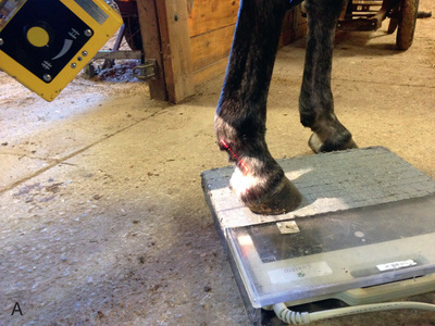
 FIG. 24.17 A, Positioning for the palmaroproximal-palmarodistal oblique (flexor/caudal tangential/skyline) view of the navicular bone. B, Anatomy of the skyline view of the navicular bone. This view highlights the flexor surface of the navicular bone and allows the distinction between the cortex and medulla to be visualized. C, Radiograph of the palmaroproximal skyline of the navicular bone. (A courtesy Stacey Thompson, BSc, RVT, McKee-Pownall Equine Services; C courtesy Carolyn Bennet, Ontario Veterinary College, Veterinary Teaching Hospital, Diagnostic Imaging at University of Guelph, Ontario.)
 - Central Ray: On the midpoint between the bulbs of the heel at the distal-palmar (or distal-plantar) fetlock. The central ray must be angled tangentially in the same plane as the flexor cortex.
- Beam: Along the palmar or plantar surface on the midsagittal plane at about 65 degrees with the ground.
- Collimate: To include area of interest, ensuring that labels are included and borders are visible.
Comments
- • This view shows the flexor surface, palmar cortex, and medulla of the navicular bones.3
- • Decrease the SID to 20 inches and adjust the exposure factors accordingly.
- • Full patient preparation is required.
- • Take advantage of any nerve blocks, and perform the study before the anesthetic wears off, if possible.
- • Keep a small field of exposure to minimize scatter radiation.
- • Extending the affected foot caudally to the opposite limb and leaning the limb and fetlock slightly forward keeps the fetlock out of the field of view.
- • This view also applies to the hind limb. For radiographing the rear feet, it is physically safer for the machine and restrainer if the hind limbs are kept in a normal position.
Technician Notes
Common problems for imaging the skyline of the navicular bone of the front limb include not extending the foot far enough forward, improper foot preparation (cleaning and packing), and not angling the central ray proximally enough.
Oblique Views of the Navicular Bone
Oblique views of the navicular bone are as follows:
- DLPMO: Dorsal 65-degree proximal, 45-degree lateral–palmarodistomedial oblique (D65Pr45L-PaDiMO)
- DMPLO: Dorsal 65-degree proximal, 45-degree medial–palmarodistolateral oblique (D65Pr45M-PaDiLO)
The oblique views do not superimpose the wings, so fractures are more easily diagnosed.
Positioning, Central Ray, and Collimation
Positioning, central ray, and collimation instructions are the same as those for the oblique views of the distal phalanx (see Fig. 24.12).
The Pastern
Middle and Proximal Phalanx, Proximal Interphalangeal Joint (Pastern)
The main indications for radiography of the middle and proximal phalanx and proximal interphalangeal joint are lameness localized with clinical examination or diagnostic analgesia and penetrating wounds. Specific views of this area are best obtained with the horse bearing weight squarely on all four limbs.
Lateral: Lateromedial View of the Pastern
The lateromedial view of the pastern provides information on the integrity of the foot axis and the bones and joints in the digit.
- Patient: Is weight-bearing.
- Foot: Placed on a block.
- Image Receptor: Placed on medial side of leg, perpendicular to the ground (Fig. 24.18).
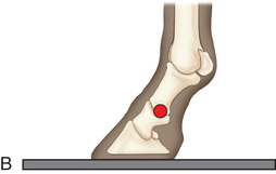
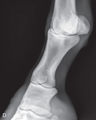
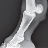 FIG. 24.18 A, Positioning for the lateromedial view of the middle and proximal phalanx and proximal interphalangeal joint (pastern). B, Radiographic anatomy of the middle and proximal phalanx and proximal interphalangeal joint (pastern). C, Radiograph of lateromedial middle and proximal phalanx and proximal interphalangeal joint (pastern). (A courtesy Shannon Brownrigg; C courtesy Carolyn Bennet, Ontario Veterinary College, Veterinary Teaching Hospital, Diagnostic Imaging at University of Guelph, Ontario.)
 - Central Ray: On proximal pastern joint (interphalangeal joint) or the joint of interest.
- Beam: Is parallel to the ground, 90 degrees to the midsagittal plane.
- Include: P2, the proximal interphalangeal joint, P1, and the interphalangeal-metacarpal joint.
- Collimate: To include the area of interest, ensuring that labels are included and borders are visible.
Comments
- • Look at the foot from the front to see whether there is angulation of the digit.
- • If there is a conformation problem, the angle of the beam may need to be adjusted.
- • This view also applies to the hind limb, with the term plantar being substituted for palmar.
Technician Notes
The technique is similar for imaging the lateral views of the lower limbs. What differs is the centering and what is included.
Dorsopalmar (DP): Dorsoproximal-Palmarodistal Oblique (D30-45Pr-PaDiO) View of the Pastern
The dorsopalmar (D30-45Pr-PaDiO) view of the pastern is a standard view to evaluate the causes of forelimb and hind limb lameness. Additional views of the opposite limb are indicated in patients less than 9 months of age. Comparison studies permit evaluation of physeal closure.2
- Patient: Is weight-bearing. Clean the hair coat.
- Image Receptor: Placed caudal to the limb (palmar or plantar), keeping it parallel to the phalanges (Fig. 24.19).
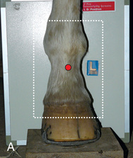
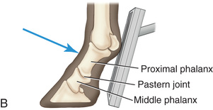
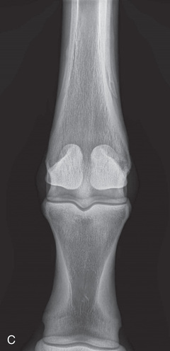 FIG. 24.19 A, Positioning for the dorsopalmar/dorsoplantar view of the middle and proximal phalanx and proximal interphalangeal joint (pastern). B, Radiographic anatomy of the dorsal aspect of the middle and proximal phalanx and proximal interphalangeal joint (pastern). C, Radiograph of the dorsopalmar/dorsoplantar view of the middle and proximal phalanx and proximal interphalangeal joint (pastern). (A courtesy Shannon Brownrigg; C courtesy Carolyn Bennet, Ontario Veterinary College, Veterinary Teaching Hospital, Diagnostic Imaging at University of Guelph, Ontario.)
 - Beam: On the midsagittal plane perpendicular to the foot axis.
- Central Ray: About 30-degree to 45-degree angle with the ground but always perpendicular to the foot axis.
- Include: P2, the proximal interphalangeal joint, P1, and the interphalangeal-metacarpal joint.
- Collimate: To include the area of interest, ensuring that labels are included and borders are visible.
Comments
- • The joint space appears narrowed on one side if the horse is not standing straight. Elevate the opposite forefoot to ensure that the horse is bearing full weight.
- • This view also applies to the hind limb, with the term plantar being substituted for palmar.
Technician Notes
Because of the foot conformation, the central ray is angled to the ground but perpendicular to the hoof wall. Thus the DP views of the foot taken with an angled beam with the ground are correctly referred to as dorsoproximal-palmarodistal oblique views (e.g., D30-45Pr-PaDiO means that the beam is angled 30-45 degrees to the ground). Note the angle is between the dorsal (D) and proximal (Pr) designations, indicating beam direction from the front of the limb. There is no lateral or medial designation.
Oblique Views of the Pastern
Oblique views of the pastern are as follows (Fig. 24.20):
- Patient: Is weight-bearing.
- Foot: Placed on a block.
- Image Receptor: Placed perpendicular to the ground against the lateral side of the limb for the DMPLO view and against the medial side for the DLPMO.
- Limb: Can be positioned as for a DP view, with the image receptor directly caudal to the limb, if a cassette slot is used, but there will be distortion of the limb.
- Central Ray: On the proximal interphalangeal joint or the area of interest.
- Beam: At a 35-degree angle with the ground and perpendicular to the foot axis.
- X-ray Tube: Rotated as follows:
- Include: P2, the proximal interphalangeal joint, P1, and the interphalangeal-metacarpal joint.
- Collimate: To include the area of interest, ensuring that labels are included and borders are visible.
Comments
- • Note that the beam is at an oblique angle both to the ground (D35Pr) and to the midsagittal plane (35L or 35M).
- • These oblique views detect areas of new bone production that are located medially and laterally from the palmar/plantar and dorsal borders of the phalanges, as well as indicating new bone formation around the joints.3
- • Chip fractures of the phalanges are best visualized on oblique views.3
- • Dorsoproximal-palmarodistal oblique views made by aligning the beam at right angles to the dorsal surface of the pastern and the parallel image receptor result in less distortion, specifically for assessment of the middle phalanx or proximal interphalangeal joint.3
- • Using a wood block with a 35-degree groove (to hold the image receptor) eliminates the need for a person to hold the plate.
- • This view also applies to the hind limb, with the term plantar being substituted for palmar.
Technician Notes
Remember that for DLPMO/DMPLO views, the last letter before the O (oblique) tells us which side is against the film, so the beam has to come from the opposite side. To tell which bones will be in profile, after the “O” is dropped, take the middle two and outer two letters. Thus for a DLPMO view, you can see the lateral sesamoid (which is grayer and more magnified), so it is the dorsomedial and lateropalmar surfaces that are highlighted.
Metacarpophalangeal/Metatarsophalangeal Joint/Proximal Sesamoid Bones (Fetlock)
Dorsopalmar (DP): Dorsal 10-Degree Proximal–Palmarodistal Oblique (D10Pr-PaDiO) View of the Fetlock
- Patient: Is weight-bearing. Ensure that hair is free of all debris.
- Foot: Placed on the ground or on a block.
- Image Receptor: Caudal to the limb (palmar or plantar position) (Fig. 24.21).
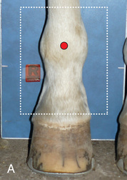
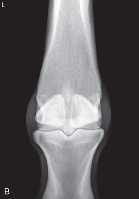 FIG. 24.21 A, Positioning for the dorsopalmar view of the metacarpophalangeal/metatarsophalangeal joint/proximal sesamoid bones (fetlock). B, Radiograph of dorsopalmar view of the metacarpophalangeal joint/proximal sesamoid bones (fetlock). (A courtesy Shannon Brownrigg; B courtesy Carolyn Bennet, Ontario Veterinary College, Veterinary Teaching Hospital, Diagnostic Imaging at University of Guelph, Ontario.)
 - Central Ray: Perpendicular to the foot axis and approximately 10- to 20-degree angle with the ground.
- Beam: On the midsagittal plane of the fetlock joint parallel to the pastern.
- Include: P1, the fetlock, and one-third of the cannon bone.
- Collimate: To include the area of interest, ensuring that labels are included and borders are visible.
Comments
- • Superimposition of the proximal sesamoid bones over the joint space can be avoided by angling the image receptor and central ray with the ground proximodistally 10 degrees for the dorsopalmar view and 15 degrees for the dorsoplantar view.3
- • This view provides visibility of the fetlock joint and the proximal sesamoid bones.
- • Additional views of the opposite limb are indicated in patients less than 12 months of age.2
- • This view also applies to the hind limb, with the term plantar being substituted for palmar.
Lateral: Lateromedial (LM) Extended View of the Fetlock
- Patient: Is weight-bearing. Clean the hair coat (Fig. 24.22).
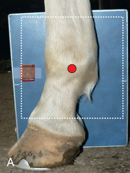
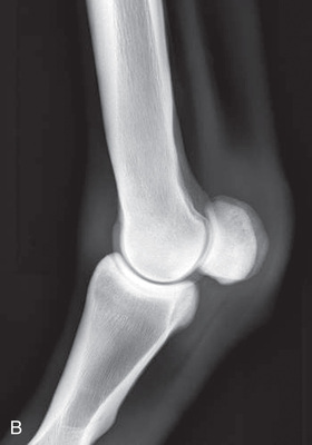 FIG. 24.22 A, Positioning for the lateromedial view of the metacarpophalangeal/metatarsophalangeal joint/proximal sesamoid bones (fetlock). B, Radiograph of the lateromedial view of the metacarpophalangeal proximal sesamoid bones (fetlock). (A courtesy Shannon Brownrigg; B courtesy Carolyn Bennet, Ontario Veterinary College, Veterinary Teaching Hospital, Diagnostic Imaging at University of Guelph, Ontario.)
 - Foot: Placed on the ground or a block.
- Image Receptor: Against medial aspect of limb and perpendicular to the ground.
- Central Ray: Medial aspect of the fetlock.
- Beam: Parallel to the ground and directed 90 degrees from the midsagittal plane.
- Include: P1, the fetlock, and a third of the cannon bone.
- Collimate: To include the area of interest, ensuring that labels are included and borders are visible.
Comments
- • Aligning the beam parallel to a line tangential to the bulbs of the heel results in a true lateromedial view. Palpation of the medial and lateral epicondyles of the third metacarpal bone may be helpful.3
- • If there is not a good image of the joint space, the horse may need to be repositioned.
- • This view contains the fetlock joint and a portion of the bones proximal and distal. A true lateromedial view displays the metacarpal condyles and superimposed sesamoids, with a visible joint space.4
- • This view also applies to the hind limb, with the term plantar being substituted for palmar.
Lateral: Lateromedial Flexed (LM) View of the Fetlock
- Foot: Supported off the ground. Completely flex the fetlock, avoiding any obliquity by pointing the midsagittal ridge at the ground (Fig. 24.23). Do not abduct the foot laterally.
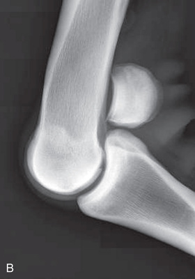 FIG. 24.23 A, Positioning for the lateromedial flexied view of the metacarpophalangeal joint/proximal sesamoid bones or fetlock. B, Radiograph of the lateral flexed view of the fetlock. (A courtesy Shannon Brownrigg; B courtesy Carolyn Bennet, Ontario Veterinary College, Veterinary Teaching Hospital, Diagnostic Imaging at University of Guelph, Ontario.)
 - Central Ray: At the medial aspect of the fetlock joint.
- Beam: Parallel to the ground and directed 90 degrees from the midsagittal plane.
- Include: P1, the fetlock, and the proximal cannon bone.
- Collimate: To include the area of interest, ensuring that labels are included and borders are visible.
Comments
- • The flexed lateromedial view allows for greater visualization of the spatial area of the metacarpophalangeal joint. The distal articular surface of metacarpal/tarsal bone is shown.
- • This view also applies to the hind limb, with the term plantar being substituted for palmar.
Technician Notes
Ensure that the restrainer is not within the beam direction and is wearing proper PPE. Collimate.
Oblique Views of the Fetlock
Oblique views of the fetlock are as follows:
- DLPMO: Dorsoproximal 45-degree lateral–palmarodistomedial oblique (DPr45L-PaDiMO) (Fig. 24.24A-B).
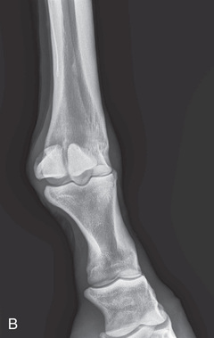
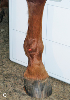
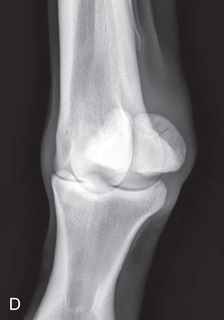 FIG. 24.24 A, Positioning for the DLPMO view of the left fetlock. Proper description of the view is dorsoproximal 45-degree lateral–palmarodistomedial oblique (DPr45L-PaDiMO). B, DLPMO view of the proximal sesamoids or fetlock joint. C, Positioning for the DMPLO view of the left front proximal sesamoids or fetlock joint. D, Radiograph of the DMPLO (DPr45M-PaDiLO) view of the proximal sesamoids or fetlock joint. (A courtesy Dr. Usha Knabe, Knabe Equine Veterinary Services, Orangeville, Ontario; B and D courtesy Carolyn Bennet, Ontario Veterinary College, Veterinary Teaching Hospital, Diagnostic Imaging at University of Guelph, Ontario.)
 - DMPLO: Dorsoproximal 45-degree medial–palmarodistolateral oblique (DPr45M-PaDiLO)
The DLPMO view is used to view the lateral sesamoid (see Fig. 24.6B and Fig. 24.24A-B), and the DMPLO to view the medial sesamoid (see Fig. 24.6A and Fig. 24.24C-D).
- Patient: Is weight-bearing.
- Foot: Placed normally under the body.
- Beam: Parallel to the ground at the middle of the joint.
- Central Ray: Angled 30 degrees to 45 degrees from the midsagittal plane in the medial or lateral direction.
- Collimate: To include area of interest, ensuring that labels are included and borders are visible.
Comments
- • The oblique views of the fetlock allow visualization of the medial and lateral sesamoid bones on the palmar/plantar aspect of the limb.
- • Depending on the personal preference of the veterinarian, the receptor can be angled slightly and the central ray is tipped to match to elevate the sesamoids away from the joint space for better visualization.
- • This view also applies to the hind limb, with the term plantar being substituted for palmar.
Technician Notes
The precise position of the central ray may vary depending on the patient conformation. It is important to be perpendicular to the area of interest and the image receptor.
Flexor/Skyline/Caudal Tangential (Palmaroproximal-Palmarodistal Oblique [PaPr-PaDiO]) View of the Fetlock (Optional View)
- Patient: Is weight-bearing.
- Foot: Placed as far back under (or behind for the hind foot) the horse as possible.
- Image Receptor: Positioned in the tunnel with the foot centered on the tunnel.
- Central Ray: In between the proximal sesamoid bones.1,2
- Beam: Should be perpendicular to the ground caudal to the front limb.
- Collimate: To include the area of interest, ensuring that labels are included and borders are visible.
Comments
- • SID is decreased because there is minimal space caudal to the front limb when the x-ray tube is placed under the horse.
- • This view allows visualization of the axial surface and abaxial recess of the proximal sesamoid bone.1,2
- • This study can also be made using an oblique view with the tube shifted either medially or laterally.
- • This view also applies to the hind limb, with the term plantar being substituted for palmar.
Extensor Surface/Skyline (Dorsoproximal-Dorsodistal [DPr-DDi]) View of the Fetlock (Optional View)
- Fetlock Joint: Fully flexed and leg is positioned forward.
- Image Receptor: Positioned against the dorsal surface of the proximal phalanx and parallel to the ground (Fig. 24.25).
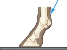 FIG. 24.25 Flexor (skyline/caudal tangential) view of the fetlock. The proper term is palmaroproximal-palmarodistal oblique (PaPr-PaDiO).
 - Central Ray: On the dorsodistal end of the third metacarpal (tarsal) bone.
- Beam: Positioned directly above the distal end of the third metacarpal (tarsal) bone almost perpendicular to the ground.
- Collimate: To include the area of interest, ensuring that labels are included and borders are visible.
Comments
- • The SID is decreased to 50 cm (20 inches).
- • This study evaluates lesions dorsal to the distal end of the third metacarpal bone, as well as soft tissue mineralization. It also detects the character of intraarticular fracture lines of the distal metacarpal bone.1,2
- • This study can be performed on the hind limb, but positioning is more difficult.
Metacarpus/Metatarsus (Cannon Bone, MII, and MIV)
Dorsopalmar (DP): Dorsoproximal-Palmarodistal (DPr-PaDi) View of the Metacarpus (Mc)/Metatarsus (Mt)
- Patient: In natural weight-bearing position.
- Image Receptor: Caudal to the palmar or plantar aspect of the limb and perpendicular to the ground (Fig. 24.26).
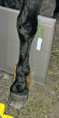
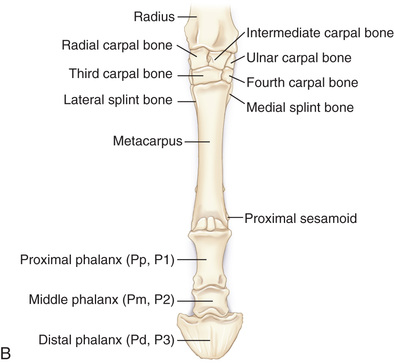
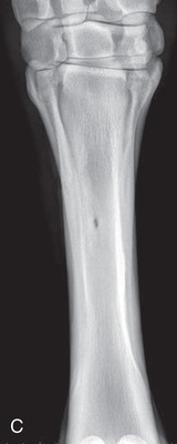 FIG. 24.26 A, Positioning of the dorsopalmar or DP of the third metacarpals (cannon bone), M2, and M4 (splint bones). Proper description of the view is dorsoproximal-palmarodistal (DPr-PDi). B, Anatomy of the third metacarpus (cannon bone), M2, and M4 (splint bones). C, Radiograph of the dorsopalmar view of the third metacarpus (cannon bone), M2, and M4 (splint bones). (C courtesy Carolyn Bennet, Ontario Veterinary College, Veterinary Teaching Hospital, Diagnostic Imaging at University of Guelph, Ontario.)
 - Central Ray: On the midsagittal plane of the third metacarpus/third metatarsus (cannon bone).
- Beam: Is parallel to the ground and perpendicular to the limb and image receptor.
- Include: Cannon bone, fetlock, and carpal/tarsal joints.
- Collimate: To include the area of interest, ensuring that labels are included and borders are visible.
Comments
- • Larger image receptors are recommended for this area.
- • This view may include both joints (distal and proximal to metacarpus). If the image receptor is not large enough, include one joint to provide orientation. Distortion is possible because of the length of the area.
- • This view also applies to the hind limb, with the term plantar being substituted for palmar.
Technician Notes
When taking radiographs, mark the center of the area to be examined with a radiolucent indicator such as tape. This maneuver may minimize repeat radiographs due to inaccurate centering and also gives a reference point if the position is to be repeated.
Technician Notes
Because the central ray is parallel to the ground and not angled, there is no oblique (O) to the DP views proximal to and including the metacarpus/metatarsus.
Lateral: Lateromedial (LM) View of the Metacarpus (Mc)/Metatarsus (Mt)
- Patient: In natural weight-bearing position.
- Image Receptor: Against the medial aspect of the cannon bone (Fig. 24.27).
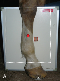
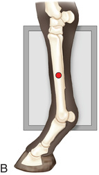
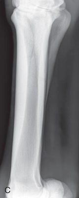 FIG. 24.27 A, Positioning for the lateral extended (lateromedial) view of the third metacarpus (cannon bone), M2, and M4 (splint bones). B, Anatomy of the lateral extended (lateromedial) view of the third metacarpus (cannon bone), M2, and M4 (splint bones). C, Radiograph of the lateral extended (lateromedial) of the third metacarpus (cannon bone), M2, and M4 (splint bones). (A courtesy Shannon Brownrigg; B courtesy Carolyn Bennet, Ontario Veterinary College, Veterinary Teaching Hospital, Diagnostic Imaging at University of Guelph, Ontario.)
 - Central Ray: On the midshaft of the cannon bone (MIII).
- Beam: Is parallel to the ground and angled 90 degrees from the midsagittal plane.
- Include: From the carpus/tarsus to the fetlock.
- Collimate: To include the area of interest, ensuring that labels are included and borders are visible.
Oblique Views of the Splint Bones
Oblique views of the metacarpus/metatarsus to view the splint bones are as follows:
- DLPMO: Dorsoproximal 45-degree lateral–palmarodistomedial oblique (DPr45L-PaDiMO)
- DMPLO: Dorsoproximal 45-degree medial–palmarodistolateral oblique DPr45M-PaDiLO
The DLPMO view is used to evaluate the lateral splint bone (M4), and the DMPLO to evaluate the medial splint bone (M2).
- Patient: In natural weight-bearing position.
- Image Receptor: Is placed on the lateral or medial aspect of the limbs, against the plantar or palmar surface (Fig. 24.28).
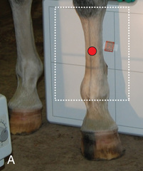
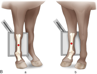
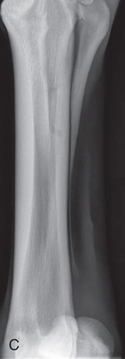
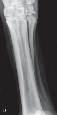 FIG. 24.28 A, Positioning for the DMPLO view of the third metacarpus (cannon bone), M2, and M4 (splint bones). The proper description is dorsoproximal 45-degree medial–palmarodistolateral oblique (DPr45M-PaDiLO). B, Anatomy of the DLPMO (a) and DMPLO (b) radiographic views of the third metacarpus (cannon bone), M2, and M4 (splint bones). C, Radiograph of the DLPMO view of the third metacarpus (cannon bone), M2, and M4 (splint bones), to show the lateral splint bone or M4. D, DMPLO radiograph to show the medial splint bone or M2. (A courtesy Dr. Usha Knabe, Knabe Equine Veterinary Services, Orangeville, Ontario; C and D courtesy Carolyn Bennet, Ontario Veterinary College, Veterinary Teaching Hospital, Diagnostic Imaging at University of Guelph, Ontario.)
 - Beam: Is centered on the midshaft of the cannon bone parallel to the ground as follows:
- DLPMO view: Central ray: directed 35 degrees to 45 degrees laterally from the midsagittal plane. The image receptor is against the medial plane of the metacarpus.
- DMPLO view: Central ray: directed 35 degrees to 45 degrees medially from the midsagittal plane. The image receptor is against the lateral plane of the metacarpus.
- Collimate: To include the area of interest, ensuring that labels are included and borders are visible.
Carpus
The carpus consists of three principal joints with articulation between adjacent bones in each row of carpal bones. This causes overlying images, which may confuse interpretation. Consequently, it is recommended to obtain a minimum of five standard views.3
Dorsopalmar (DP): Dorsoproximal-Palmarodistal (DPr-PaDi) View of the Carpus
- Patient: In natural weight-bearing position.
- Image Receptor: Placed vertically on the palmar aspect of the limb and perpendicular to the beam and ground (Fig. 24.29).
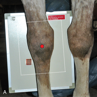
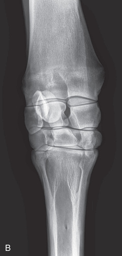
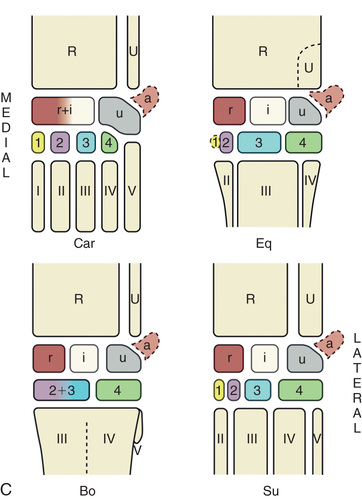 FIG. 24.29 A, Positioning for the DP (dorsoproximal-palmarodistal) (DPr-PaDi) view of the carpus. B, Radiograph of the DP (dorsoproximal-palmarodistal) (DPr-PaDi) view of the carpus. C, Schematic diagrams of the bones of the carpal skeleton in carnivore (Car), horse (Eq), cattle (Bo), and pig (Su). (A courtesy Shannon Brownrigg; B courtesy Carolyn Bennet, Ontario Veterinary College, Veterinary Teaching Hospital, Diagnostic Imaging at University of Guelph, Ontario.)
 - Opposite Limb: May have to be elevated.
- Central Ray: To the middle of the carpus at a true DP plane, centering on an imaginary line from the middle of the foot wall to the radius.
- Beam: Is parallel to the ground and perpendicular to the carpus and image receptor.
- Include: The entire carpus and a portion of each of the metacarpal bones and radius/ulna.
- Collimate: To include the area of interest, ensuring that labels are included and borders are visible.
Comments
- • To see whether there is closure of the distal radial physis in young horses, the other limb may be required for comparison.
- • The orientation of the central ray is perpendicular to the limb in question, not to the body of the horse.
- • On the radiograph, the intercarpal space between the radial and intermediate carpal bones should be visible with no superimposition.
Lateral: Lateromedial (LM) Extended View of the Carpus
- Patient: In natural weight-bearing position.
- Image Receptor: Placed vertically at the medial aspect of the limb (Fig. 24.30).
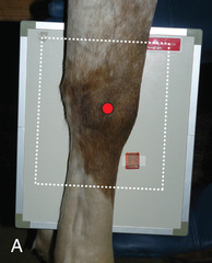
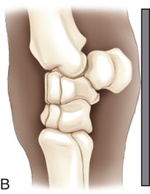
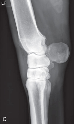 FIG. 24.30 A, Positioning for the lateromedial view of the carpus. B, Anatomy of the lateromedial view of the carpus. C, Radiograph of the lateromedial view of the carpus. (A courtesy Shannon Brownrigg; C courtesy Carolyn Bennet, Ontario Veterinary College, Veterinary Teaching Hospital, Diagnostic Imaging at University of Guelph, Ontario.)
 - Central Ray: Angled 90 degrees from the dorsal midline.
- Beam: Parallel to the ground and perpendicular to the carpus and image receptor.
- Include: Entire carpus.
- Collimate: To include the area of interest, ensuring that labels are included and borders are visible.
Comments
- • A true LM view displays all carpal bones superimposed over one another, allowing for a clear view of the dorsal surfaces. A small portion of the distal and proximal bones, along with a full view of the carpus, should be visible. The carpus is a very complex joint. Multiple views may be required.
- • Consideration must be given to mature versus immature development.
Lateral: Lateromedial (LM) Flexed View of the Carpus
- Limb of Interest: Elevated and carpus flexed to approximately three-quarters of full flexion. Support the foot at the level of the carpus of the opposite limb so the carpus is slightly dorsal to the limb. Keep the carpus under the body, and prevent abduction (Fig. 24.31).
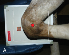
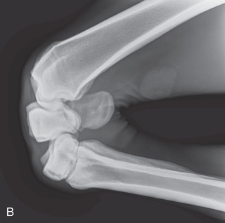 FIG. 24.31 A, Positioning for lateromedial flexed view of the carpus. B, Radiograph of the lateromedial flexed view of the carpus. (A courtesy Shannon Brownrigg; B courtesy Carolyn Bennet, Ontario Veterinary College, Veterinary Teaching Hospital, Diagnostic Imaging at University of Guelph, Ontario.)
 - Image Receptor: Vertically against the medial aspect of the carpus.
- Central Ray: Over the lateral aspect of the limb in the middle of the carpus.
- Beam: Parallel to the ground, 90 degrees from the midsagittal plane, and perpendicular to the image receptor.
- Include: Entire carpus.
- Collimate: To include the area of interest, ensuring that labels are included and borders are visible.
Oblique Views of the Carpus
Oblique views of the carpus are as follows:
- Patient: In natural weight-bearing position.
- Image Receptor: Is placed vertically against the palmarolateral or the palmaromedial side, depending on the projection (Fig. 24.32).
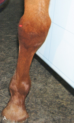
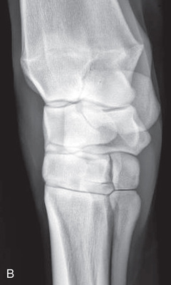
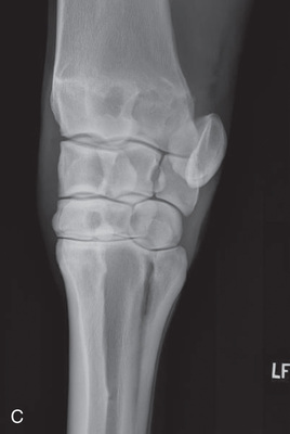 FIG. 24.32 A, Positioning for the DMPLO view of the carpus. The proper description is the dorsoproximal 45-degee medial–palmarodistolateral oblique (DPr45M-PaDiLO). Place the limb as close as possible to the image receptor. B, Radiograph of the DMPLO view of the carpus. C, Radiograph of the DLPMO view of the carpus. (A courtesy Dr. Usha Knabe, Knabe Equine Veterinary Services, Orangeville, Ontario; B and C courtesy Carolyn Bennet, Ontario Veterinary College, Veterinary Teaching Hospital, Diagnostic Imaging at University of Guelph, Ontario.)
 - X-ray Tube: In front of the limb and perpendicular to the image receptor.
- Central Ray: On middle of the carpus.
- Include: Entire carpus and a portion of the metacarpal bones and radius if possible.
- Beam: Is parallel to the ground and perpendicular to the image receptor.
- DMPLO view: Position the central ray medially 45 degrees to 60 degrees from the dorsal midline (with the image receptor against the palmarolateral aspect).
- DLPMO view: Position the central ray laterally 45 degrees to 60 degrees from the dorsal midline (with the image receptor against the palmaromedial aspect).
- Include: The dome of the carpus.
- Collimate: To include the area of interest, ensuring that labels are included and borders are visible.
Skyline: Flexed Dorsoproximal–Dorsodistal Oblique (DPr-DDiO) Views of the Distal Radius, Proximal Row of Carpal Bone, and the Distal Carpal Row1
- Limb: Elevated and carpus flexed so the metacarpals are horizontal and parallel to the ground for all the views.
- Image Receptor: Placed firmly against the dorsal surface of the proximal metacarpus, parallel to the ground (Fig. 24.33).
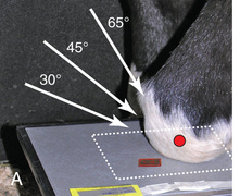
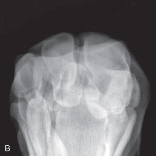
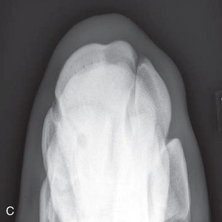 FIG. 24.33 A, Positioning for the skyline view of the carpus or the dorsoproximal–dorsodistal oblique flexed views (DPr-DDiO). B, Radiograph of a 60-degree, dorsoproximal-dorsodistal oblique flexed (skyline) view (D60Pr-DDiO) of the distal row of carpal bones. C, Radiograph of the distal row of carpal bones with a 30-degree angle. (A courtesy Dr. Usha Knabe, Knabe Equine Veterinary Services, Orangeville, Ontario; B and C courtesy Carolyn Bennet, Ontario Veterinary College, Veterinary Teaching Hospital, Diagnostic Imaging at University of Guelph, Ontario.)
 - Central Ray: Aimed toward the midsagittal plane of the dorsal surface of the carpus. The exact location and angle of the beam to the image receptor vary, depending on the row of carpal bones being imaged, is as follows:
- Include: Carpus.
- Collimate: To include the area of interest, ensuring that labels are included and borders are visible.
Radius/Ulna
Craniocaudal (CrCd): Cranioproximal-Caudodistal (CrPr-CdDi) View of the Radius/Ulna
- Patient: In natural weight-bearing position.
- Image Receptor: Is on the caudal aspect of the limb and perpendicular to the ground (Fig. 24.34).
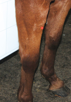 FIG. 24.34 Positioning for the craniocaudal (CrCd) (cranioproximal-caudodistal) view of the radius and ulna. (Courtesy Dr. Usha Knabe, Knabe Equine Veterinary Services, Orangeville, Ontario.)
 - Central Ray: Cranioproximally on the midsagittal plane of the radius/ulna at the point of injury or the location of pain or swelling.
- Beam: Is directed slightly downward so it is perpendicular to the limb and image receptor.
- Include: At least one joint for orientation.
- Collimate: To include the area of interest, ensuring that labels are included and borders are visible.
Comments
- • Studies made of the area generally require a long image receptor. It is difficult to include the entire bone on a single radiograph.
- • A cassette holder should be utilized to decrease radiation exposure to personnel.
- • If the affected limb is uppermost in a recumbent patient, either a craniocaudal or caudocranial view is possible.
Lateral: Lateromedial (LM) View of the Radius/Ulna
- Patient: In natural weight-bearing position.
- Image Receptor: Is against the medial aspect of the radius/ulna (Fig. 24.35).
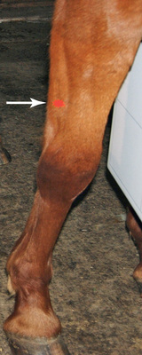 FIG. 24.35 Positioning for the lateral view of the radius and ulna. (Courtesy Dr. Usha Knabe, Knabe Equine Veterinary Services, Orangeville, Ontario.)
 - Beam: Is parallel to the ground and angled 90 degrees from the midsagittal plane.
- Center: On the radius/ulna at the point of injury or pain.
- Include: At least one joint to provide orientation.
- Collimate: To include the area of interest, ensuring that labels are included and borders are visible.
Elbow (Brachioantebrachial Joint)
The elbow joint is difficult to radiograph while the animal is in a standing position because of its proximity to the ventral body wall. The use of general anesthesia is preferred if possible. Because of the increased thickness of the limb, higher-capacity x-ray equipment is required.
Craniocaudal (CrCd): Cranioproximal-Caudodistal (CrPr-CdDi) View of the Elbow
- Patient: In standing position, extend the limb as far cranial as possible. If the patient is anesthetized and in lateral recumbency, abduct the limb and extend it away from the body wall.
- Foot: Elevated off the ground.
- Image Receptor: Placed against the radius/ulna, pushing medially against the ventrolateral thorax caudal to the olecranon (Fig. 24.36).
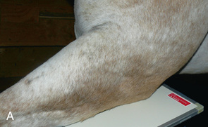
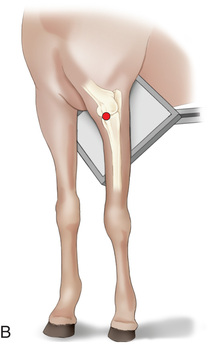
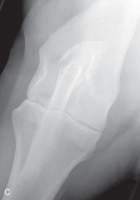 FIG. 24.36 A, Positioning for the craniocaudal view of the elbow (brachioantebrachial joint). B, Anatomy of the craniocaudal view of the elbow. C, Radiograph of the craniocaudal view of the elbow. (C courtesy Carolyn Bennet, Ontario Veterinary College, Veterinary Teaching Hospital, Diagnostic Imaging at University of Guelph, Ontario.)
 - Central Ray: In a cranioproximal-caudodistal direction through the cranial aspect of the joint.
- Beam: Perpendicular to the image receptor and the limb.
- Include: The olecranon and a portion of the radius and ulna.
- Collimate: To include the area of interest, ensuring that labels are included and borders are visible.
Comments
- • Because of its proximity to the ventral body wall, this joint is difficult to radiograph.
- • It may be beneficial to have a different person flexing the tarsus than supporting the receptor plate, but ensure all wear PPE.
- • This view shows the humeroradial joint space and medial and lateral aspects of the humerus and radius.
- • Lifting the foot off the ground partially separates the elbow from the chest wall.
- • If the patient is weight-bearing, the central ray will be more horizontal to the ground. Place the image receptor with the long edge pressed firmly against the ventrolateral thorax at the caudal aspect of the elbow. Extend the lower inner corner ventral to the thorax to include the distal humerus.
Lateral: Mediolateral (ML) View of the Elbow
With the patient standing, the mediolateral view is the easiest positioning for the elbow and is often suitable for a portable x-ray unit.
- Affected Limb: Pulled cranially as far as possible.
- Limb: Is elevated and manually pulled forward so the radius is parallel to the ground.
- Image Receptor: Firmly placed against the lateral aspect of the limb, with the elbow joint centered to the image receptor. The image receptor must remain perpendicular to the ground (Fig. 24.37A).
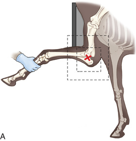
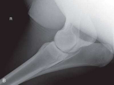
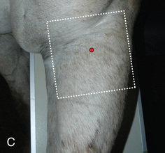 FIG. 24.37 A, Positioning for the mediolateral view of the elbow. B, Radiograph of the mediolateral view of the elbow. C, Lateromedial view of the elbow. (B courtesy Carolyn Bennet, Ontario Veterinary College, Veterinary Teaching Hospital, Diagnostic Imaging at University of Guelph, Ontario; C courtesy Shannon Brownrigg.)
 - Central Ray: On the elbow joint.
- Beam: Parallel to the ground, toward the medial side of the elbow joint just cranial to the opposite forelimb.
- Include: The entire joint in collimation.
- Collimate: To include the area of interest, ensuring that labels are included and borders are visible.
Comments
- • Forward extension is required for an adequate projection.
- • It may be beneficial to have a different person flexing the tarsus than supporting the receptor plate, but ensure all wear PPE.
- • If the limb cannot be extended, the patient may need to be bearing weight on the limb and a lateromedial view obtained with the image receptor positioned against the medial aspect (see Fig. 24.37C). The distal humerus or olecranon is not as well visualized with this position.
- • A recumbent study is best with the patient in lateral recumbency.
Shoulder
To attain quality projections of the shoulder joint, the use of general anesthesia and placement of the patient in lateral recumbency are recommended. The standing position may be possible if the patient tolerates manipulation. The easiest and maybe only view of the shoulder that can be obtained is the mediolateral.
Lateral: Mediolateral (ML) View of the Shoulder
- Affected Limb: Elevated forward and pulled cranially with the radius parallel to the ground. Superimpose the humeral head over the soft tissue of the neck.
- Image Receptor: Firmly placed against the lateral aspect of the shoulder joint (Fig. 24.38).
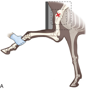
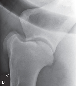
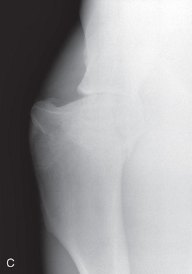 FIG. 24.38 A, Positioning for the mediolateral view of the shoulder joint. B, Radiograph of the mediolateral view of the equine shoulder joint. C, Radiograph of the CrPr45M-CaDiLO of the shoulder joint. (B and C courtesy Carolyn Bennet, Ontario Veterinary College, Veterinary Teaching Hospital, Diagnostic Imaging at University of Guelph, Ontario.)
 - X-ray Tube: On the opposite side of the patient.
- Beam: Parallel to the ground and perpendicular to the image receptor, centered on the joint.
- Central Ray: On the scapulohumeral joint, palpate the distal aspect of the spine of the scapula of the opposite limb and aim cranial and proximal 10 cm (4 inches).1
- Include: The proximal humerus and distal spine of the scapula.
- Collimate: To include the area of interest, ensuring that labels are included and borders are visible.
Comments
- • If injury to the supraglenoid process is suspected, direct the central ray more dorsocaudally.
- • If there is injury to the tubercles, direct the central ray more ventrocaudally.2
Oblique View of the Shoulder
- CrMCdLO1: Cranioproximal 45-degree medial–caudodistolateral oblique (CrPr45M-CaDiLO) (Fig. 24.38C)
- Patient: Standing with the affected limb in a normal position slightly cranial to the opposite limb. An assistant should pull the distal aspect of the affected limb cranially as far as possible.
- Image Receptor: Placed cranial and lateral to the affected shoulder joint against the pectoral muscle mass.
- Beam: Parallel to the ground directed craniomedial to caudolateral aimed at the shoulder joint.
- Include: The proximal humerus and distal spine of the scapula.
- Collimate: To include the area of interest, ensuring that labels are included and borders are visible.
Pelvic Limb Proximal to and Including the Tarsus
Tarsus
Dorsoplantar (DP): Dorsoproximal-Plantarodistal (DPr-PlDi) View of the Tarsus
- Patient: In natural weight-bearing position for the affected limb; opposite limb may have to be elevated.
- Image Receptor: The vertical image receptor is caudal to the limb on the plantar aspect (Fig. 24.39).
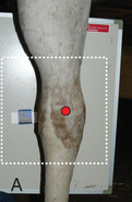
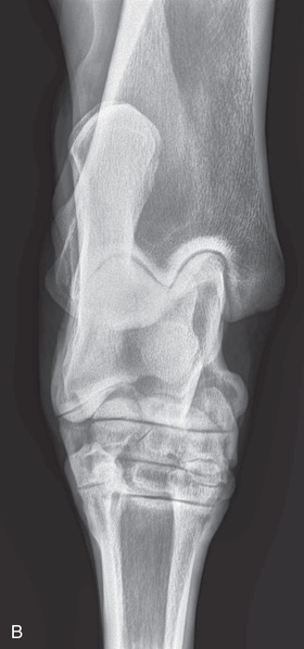
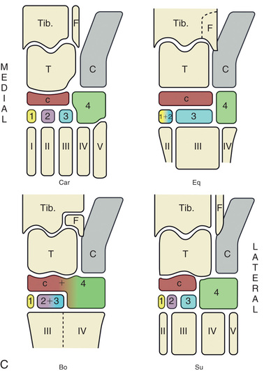 FIG. 24.39 A, Positioning for the DP (dorsoproximal-plantarodistal) (DPr-PlDi) view of the tarsus. B, Radiograph of the DP view of the tarsus. C, Schematic diagrams of the bones of the tarsal skeleton in carnivore (Car), horse (Eq), cattle Bo), and pig (Su). (A courtesy Shannon Brownrigg; B courtesy Carolyn Bennet, Ontario Veterinary College, Veterinary Teaching Hospital, Diagnostic Imaging at University of Guelph, Ontario.)
 - Central Ray: Centered mid-joint on the midsaggital plane.
- Beam: Is parallel to the ground and perpendicular to the tarsus and image receptor.
- Include: The entire tarsus, a portion of each of the metatarsal bones, and the medial and lateral malleoli of the tibia.
- Collimate: To include the area of interest, ensuring that labels are included and borders are visible.
Lateral: Lateromedial (LM) Extended View of the Tarsus
- Patient: In natural weight-bearing position. Keep the tarsus under the body, and prevent abduction (Fig. 24.40).
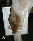
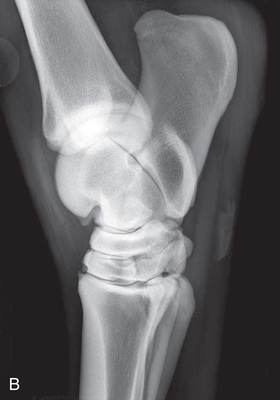 FIG. 24.40 A, Positioning for the lateromedial (LM) view of the tarsus. B, Radiograph of lateromedial (LM) view of the tarsus. (A courtesy Shannon Brownrigg; B courtesy Carolyn Bennet, Ontario Veterinary College, Veterinary Teaching Hospital, Diagnostic Imaging at University of Guelph, Ontario.)
 - Image Receptor: Perpendicular to the ground against the medial aspect of the tarsus.
- Central Ray: Over the lateral aspect of the limb in the middle of the tarsal joint.
- Beam: Parallel to the ground and 90 degrees from the midsagittal plane.
- Include: The entire tarsal joint and calcaneus.
- Collimate: To include the area of interest, ensuring that labels are included and borders are visible.
Lateral: Lateromedial Flexed (LM) View of the Tarsus
- Limb of Interest: Is elevated, and the tarsus as flexed as the horse will allow. Support the foot at the level of the tarsus of the opposite limb with the affected tarsus slightly dorsal to the limb. Keep the tarsus under the body, and prevent abduction (Fig. 24.41).
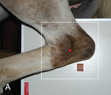
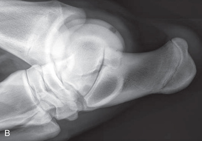 FIG. 24.41 A, Positioning for the lateromedial flexed view of the tarsus. B, Radiograph of the lateromedial flexed view of the tarsus. (A courtesy Shannon Brownrigg; B courtesy Carolyn Bennet, Ontario Veterinary College, Veterinary Teaching Hospital, Diagnostic Imaging at University of Guelph, Ontario.)
 - Image Receptor: Vertically placed against the medial aspect of the tarsus.
- Central Ray: Perpendicular to the image receptor over the lateral aspect of the limb at the talus.
- Beam: Parallel to the ground and angled 90 degrees from the midsagittal plane.
- Include: Point of the hock, distal tibia, and proximal metatarsal bones.
- Collimate: To include the area of interest, ensuring that labels are included and borders are visible.
Comments
- • Care must be taken when flexing the tarsus to monitor the comfort level of the patient.
- • It may be beneficial to have a different person flexing the tarsus than supporting the receptor plate. All must wear PPE.
Technician Notes
If joint space is not properly visible on the radiograph, try repositioning the horse. Minor adjustments to their stance can greatly affect the ability to properly image the joint spaces.
Oblique Views of the Tarsus
Oblique views of the tarsus are as follows:
- Patient: In natural weight-bearing position.
- Image Receptor: Placed vertically against the plantaromedial or plantarolateral aspect of the tarsus (Fig. 24.42).
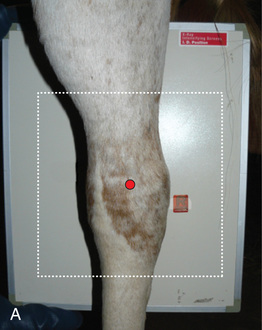
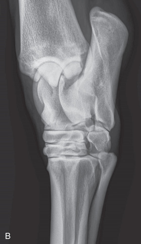
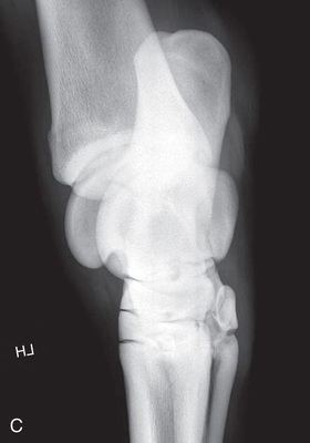 FIG. 24.42 A, The DLPMO of the tarsus. The accurate positioning term is dorsoproximal 45-degree lateral-plantarodistomedial oblique (DPr45L-PlDiMO). B, Radiograph of the DLPMO view of the tarsus. C, Radiograph of the DMPLO view of the tarsus. (A courtesy Shannon Brownrigg; B courtesy Carolyn Bennet, Ontario Veterinary College, Veterinary Teaching Hospital, Diagnostic Imaging at University of Guelph, Ontario.)
 - Central Ray: Directed horizontally to center on the central tarsal bone.
- Beam: Parallel to the ground at 45 degrees laterally or medially to the MSP.
- X-ray Tube: In front of the limb and perpendicular to the image receptor.
- DLPMO view: Position the central ray laterally 45 degrees to 60 degrees from the dorsal midline (with the image receptor against the plantaromedial aspect).
- DMPLO view: Position the central ray medially 45 degrees to 60 degrees from the dorsal midline (with the image receptor against the plantarolateral aspect).
- Collimate: To include the area of interest, ensuring that labels are included and borders are visible.
Skyline: Flexed Plantaroproximal-Plantarodistal (PlPr-PlDi) View of the Tuber Calcaneus and Sustentaculum Tali
- Limb: Elevated and tarsus joint flexed so that the metatarsal bones are parallel with the ground and horizontal for all views.
- Image Receptor: Placed horizontally and firmly against the plantar surface of the calcaneus, parallel to the ground (Fig. 24.43).
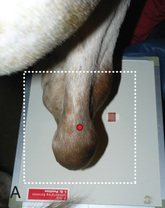
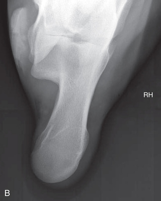 FIG. 24.43 A, Positioning of the tuber calcaneus for the skyline flexed or plantaroproximal-plantarodistal (PlPr-PlDi) view. B, Radiograph of the tuber calcaneus for the skyline flexed or plantaroproximal-plantarodistal (PlPr-PlDi) view. (A courtesy Shannon Brownrigg; B courtesy Carolyn Bennet, Ontario Veterinary College, Veterinary Teaching Hospital, Diagnostic Imaging at University of Guelph, Ontario.)
 - Central Ray: On the tuber calcaneus.
- Beam: Directly above the tarsus, perpendicular to the ground, and aimed straight down, being as perpendicular to the image receptor as possible, with a slight cranial angulation, to avoid the thigh musculature.
- Include: Only the calcaneus and sustentaculum tali.
- Collimate: To include the area of interest, ensuring that labels are included and borders are visible.
Comments
- • This skyline flexed view provides evaluation of the calcaneus and the sustentaculum tali from a proximal-to-distal direction without overlying bony shadows.1,2
- • It may be beneficial to have a different person flexing the tarsus than supporting the receptor plate, but ensure all wear PPE.
- • The use of a ceiling-mounted x-ray unit is preferred because of the height of the positioning of the tube head required.
Tibia/Fibula
Caudocranial (CdCr): Caudioproximal-Cranioodistal (CdPr-CrDi) View of the Tibia/Fibula
- Patient: In natural weight-bearing position.
- Image Receptor: Cranial to the cranial aspect of the limb and parallel with the limb (Fig. 24.44).
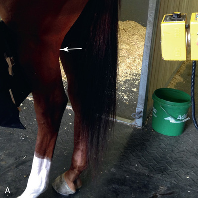
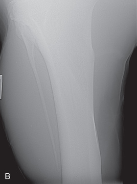 FIG. 24.44 A, Positioning for the CdCr view of the tibia/fibula. B, Radiograph of the CdCr view of the tibia/fibula. (Courtesy Stacey Thompson, BSc, RVT, McKee-Pownall Equine Services.)
 - Central Ray: On the midsagittal plane of the tibia/fibula at the point of injury or the location of pain or swelling.
- Beam: Slightly directed downward so it is perpendicular to the limb and image receptor.
- Include: At least one joint for orientation.
- Collimate: To include the area of interest, ensuring that labels are included and borders are visible.
Comments
- • Studies made of the area generally require a long image receptor. It is difficult to include the entire bone on a single radiograph.
- • A cassette holder should be utilized to decrease both physical and radiation danger.
- • The study can be made as the craniocaudal view, with the image receptor against the caudal aspect of the limb and the x-ray tube positioned cranially. However, there is increased OFD and concern with positioning safety.
Lateral: Lateromedial (LM) View of the Tibia/Fibula
- Patient: In natural weight-bearing position.
- Image Receptor: Against the medial aspect of the tibia/fibula (Fig. 24.45).
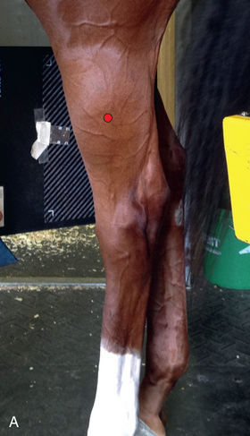
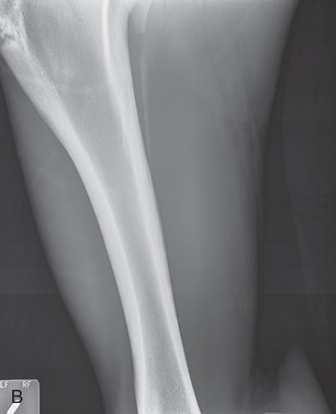 FIG. 24.45 A, Positioning for the lateromedial view of the tibia/fibula. B, Radiograph of the lateromedial view of the tibia/fibula. (Courtesy Stacey Thompson, BSc, RVT, McKee-Pownall Equine Services.)
 - Central Ray: On the tibia/fibula at the point of injury or pain.
- Beam: Parallel to the ground and angled 90 degrees from the midsagittal plane.
- Include: The tibia/fibula and at least one joint to provide orientation.
- Collimate: To include the area of interest, ensuring that labels are included and borders are visible.
Stifle (Femorotibial Joint)
Radiography of the femorotibial joint (stifle) is difficult because of the thickness of the surrounding tissue and the sensitive nature of this region. Because of the depth of the muscle in the femoral region, the caudocranial projection demonstrates little above the joint space. Radiographs of this region should be attempted only if the patient is cooperative. Safety is paramount in radiography of the hind region of the horse. Sedation or a twitch may be used; general anesthesia is also to be considered.
Lateral: Lateromedial (LM) View of the Stifle
- Patient: In natural weight-bearing position.
- Image Receptor: Angled and cautiously placed against the medial side of the stifle joint (Fig. 24.46A). Use gentle force to push the flat edge of the image receptor as far into the medial aspect of the stifle (flank) as possible. Most patients object to this image receptor placement.
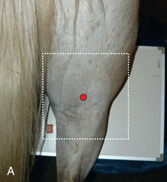
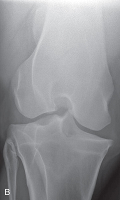 FIG. 24.46 A, Positioning for caudocranial (caudoproximal-craniodistal) view of the stifle. B, Radiograph of the caudocranial view of the stifle.
 - Central Ray: 5 to 7 cm (2 inches) proximal to the tibial plateau between cranial and middle third of the stifle region.5
- Beam: Is parallel to the floor, perpendicular to the image receptor, and 90 degrees laterally from the MSP.
- Include: The entire patellae and proximal tibia.
- Collimate: To the size of a large image receptor, ensuring that labels are included and borders are visible.
Comments
- • If the limb being imaged is slightly caudal to the opposite limb, the space may open up on the medial side of the stifle for the receptor. Angle the receptor so it is aligned with the tibia.
- • Great care must be taken because of the sensitivity of the patient in this region of the body. Gentle, calm movements are needed. All personnel involved must be prepared to respond to the patient at any moment.
- • Gently touching the medial stifle region and the flank before inserting the image receptor may help with patient compliance.
- • It is helpful to elevate the front limb to minimize motion.
- • Sedation is highly recommended, especially if kicking seems likely.
- • This view visualizes the articular surfaces of the femorotibial joints.
- • To obtain a flexed view: Either lift the limb or rest the toe on the ground, creating a “dropped” stifle position.
Caudocranial (CdCr): Caudoproximal-Craniodistal (CdPr-CrDi) View of the Stifle (Optional)
- Patient: In natural weight-bearing position.
- Image Receptor: Placed cranially to the stifle and tilted so that the long edge is snug against the body wall (Fig. 24.47). To increase the ease of image receptor placement, extend the hind limb caudally and angle the central ray 10 degrees to 20 degrees proximodistally3 (downward).
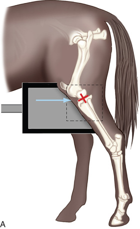
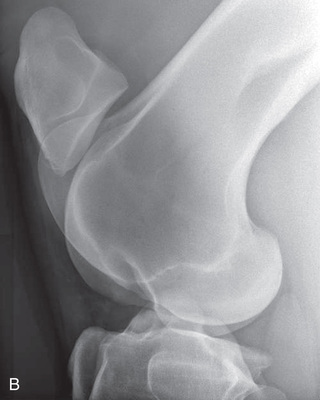 FIG. 24.47 A, Positioning for the lateromedial view of the stifle. Centering of the stifle is assisted if a piece of tape is placed at the proximal end of the tibia (arrow). B, Radiograph of the lateromedial view of the stifle. (B courtesy Carolyn Bennet, Ontario Veterinary College, Veterinary Teaching Hospital, Diagnostic Imaging at University of Guelph, Ontario.)
 - X-ray Tube: Positioned caudally to the stifle joint.
- Beam: Almost perpendicular to the image receptor.
- Central Ray: Over the stifle joint approximately 10 cm (4 inches) distal to the patella angled 10 degrees to 15 degrees proximodistally so the ray exits at the proximal cranial tibia level.1
- Include: The entire patellae and proximal tibia.
- Collimate: To include the area of interest, ensuring that labels are included and borders are visible.
Comments
- • This view is indicated to identify secondary bone growth within the joint space. The distal growth center of the femur closes at age 20 to 30 months. The apophyseal center of the tibial tuberosity joins the proximal tibial growth center at 9 to 12 months, and the combined growth centers join the tibial shaft at 20 to 30 months.2
- • Personal preference may have the receptor tipped to the angle of the tibia or directly perpendicular to the ground as long as the angle is accounted for with the central ray.
- • This view is potentially dangerous; have the receptor in position before moving in with the x-ray tube.
- • This view helps detect changes indicative of secondary joint disease and evaluate the joint width.
Technician Notes
A firm touch is less irritating than a light touch for the patient. Introduce a gloved hand before introducing the image receptor. Be sure not to come in contact with the sheath of a male horse. Keep alert to any signs of agitation displayed by the patient.
CdLCrMO: Caudoproximal 60-Degree Lateral–Craniodistomedial Oblique (CdPr60L-CrDiMO) View of the Stifle (Optional)
- Patient: In natural weight-bearing position. (Fig. 24.48).
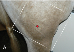
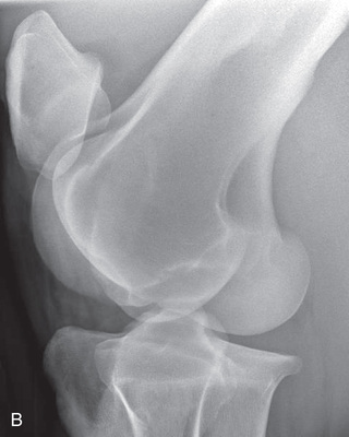 FIG. 24.48 A, Positioning of the caudolateral-craniomedial oblique view of the stifle. B, Radiograph of the caudolateral-craniomedial oblique view of the stifle. (A courtesy Shannon Brownrigg; B courtesy Carolyn Bennet, Ontario Veterinary College, Veterinary Teaching Hospital, Diagnostic Imaging at University of Guelph, Ontario.)
 - Image Receptor: Pushed as far into the flank as possible, resting it against the medial ridge of the trochlea.2
- Central Ray: Approximately 10 cm (4 inches) on the caudal aspect of the limb at the level of the femorotibial joint3 at a downward angle of 10 degrees.1
- Beam: Directed horizontally, positioned caudally and laterally 60 degrees.1
- Include: The entire patellae and proximal tibia.
- Collimate: To include the area of interest, ensuring that labels are included and borders are visible.
Skyline: Cranioproximal-Craniodistal Oblique (CrPr-CrDiO) View of the Stifle (Optional)
- Patient: In natural weight-bearing position. Lift the distal hind limb, flex, and retract it caudally to place the tibia horizontally
- Image Receptor: Positioned horizontal to the ground facing the stifle so the caudal part of the plate touches the tibial crest.
- Beam: Position dorsally and angled down to the stifle (Fig. 24.49).
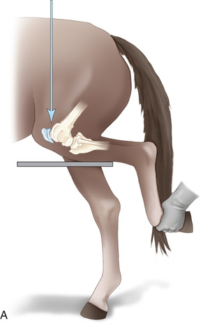
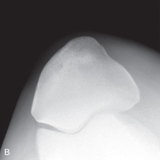 FIG. 24.49 A, Positioning for the skyline view of the stifle joint. B, Skyline radiographic view of the patella. (B courtesy Carolyn Bennet, Ontario Veterinary College, Veterinary Teaching Hospital, Diagnostic Imaging at University of Guelph, Ontario.)
 - Central Ray: Downward distally and 10 degrees lateral to medial.
- Include: Cranial patella.
- Collimate: Tightly to include the area of interest, ensuring that labels are included and borders are visible.
Comments
- • It may be beneficial to have a different person flexing the tarsus than supporting the receptor plate, but ensure all wear PPE.
- • This view is used to access fractures of the patella. The medial and lateral trochlear ridges, as well as the intertrochlear groove of the femur, are visualized.1
Pelvis and Hip Joints
General anesthesia is required for the pelvic radiographic study of a large animal patient. Young foals (or calves) can be successfully radiographed in the field, whereas larger patients (horses or cows) must be radiographed in the hospital setting because of the specific high-powered radiographic equipment required, such as a mobile or ceiling-mounted unit, to provide proper output (high kV exposure). Views may be segmented to obtain a complete pelvic view (multiple images used for a single view). If using film, the use of a table with an embedded cassette tunnel is preferred to increase ease of positioning and cassette exchange. Due to the thickness of this region, the use of a grid is suggested.
Before administration of a general anesthetic, special consideration must be given to the anesthesia recovery process for patients with pelvic fractures or luxation. As a result, a pelvic radiographic study may be contraindicated.
Ventrodorsal (VD) View of the Pelvis
- Patient: In dorsal recumbency with the hind limbs flexed in a “frog-leg” position (Fig. 24.50). Evacuation of the rectum may be required to minimize artifacts for an evaluation of the pelvic symphysis.
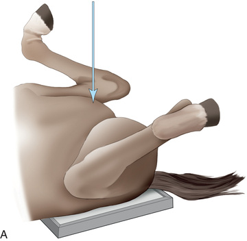
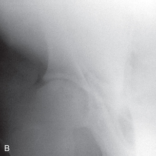 FIG. 24.50 A, Positioning for the VD view of the pelvis and coxofemerol joint. The arrow is the direction of the central ray. B, Radiograph of the acetabulum of an anesthetized patient in a ventrodorsal view. (B courtesy Carolyn Bennet, Ontario Veterinary College, Veterinary Teaching Hospital, Diagnostic Imaging at University of Guelph, Ontario.)
 - Image Receptor: Under the pelvis.
- Limbs: Positioned about 20 degrees to 30 degrees above the surface, not touching the ground or table.
- Beam: Directly vertical to the pelvis with the beam centered over the image receptor. Multiple views may be required, depending on the size of the patient.
- Central Ray: Over specific areas of interest and perpendicular to the image receptor to minimize distortion.
- Include: Entire pelvis if possible.
- Collimate: Tightly to include the area of interest, ensuring that labels are included and borders are visible.
Comments
- • It is important for both legs to be positioned at the same angle and flexion to maintain symmetry of the pelvic joints.
- • If more than one projection is necessary, each centering point should be marked with a marker or tape. Marking the centering points allow adjustments to be made from the previously exposed site.
- • For a thorough assessment, five to seven overlapping radiographs may be required.
Ventrodorsal Oblique View of the Pelvis (for Each Hip)
- Patient: Placed in a ventrodorsal position, with the hind limbs flexed (frog-leg), and pelvis then shifted 10 degrees to 20 degrees to elevate the unaffected side away from the tabletop. Rectal evacuation is not required for this position.
- Image Receptor: Positioned under the patient.
- Beam: Angled perpendicular to the image receptor.
- Central Ray: Directly vertical to the hip joint and center laterally from the midline over the hip joint of interest.2
- Include: The entire pelvis if possible.
- Collimate: Tightly to include the area of interest, ensuring that labels are included and borders are visible.
Comments
- • The oblique views are to isolate and evaluate the individual hip joint. Comparative radiographs are recommended.
- • A specific angle is not critical, provided it is possible to repeat the same angle on the opposite side.
- • X-ray positioning devices may be helpful to maintain and repeat the angle of the pelvis. Ensure that both the hind and front ends of the horse are rotated.
- • Secure the patient to prevent injury and unexpected movement. The use of ropes is critical to secure the patient on the tabletop.
- • Protective padding is recommended with the use of ropes to prevent tendon and ligament injuries.
- • The use of a cassette tunnel is preferred for ease of changing image receptors.
- • The proximal femur can also be radiographed if the beam is centered more laterally.
Head, Neck, Thorax, and Abdomen
Note that for all positions:
- Image Receptor: Is placed against the side of the skull (see Fig. 24.52) closest to the area of interest (i.e., lesion).
- X-ray Tube: Is positioned on the opposite lateral side.
- Position: The patient in a natural standing posture.
- Central Ray: On the area of interest and perpendicular to the image receptor.
- Collimate: Tightly to include the area of interest, ensuring that labels are included and borders are visible.
See Table 24.3 for further specifics.
TABLE 24.3
| BODY PART | PROJECTION | IMAGE RECEPTOR PLACEMENT | X-RAY TUBE | CENTRAL RAY | FURTHER COMMENTS |
|---|---|---|---|---|---|
| Skull | Lateral (Fig. 24.52) | Against the affected side. | Opposite lateral side. | From the opposite side on area of interest. | |
| Skull | Dorsoventral (DV) (Fig. 24.53) | Horizontal ramus against the ventral aspect of the mandible. | At the dorsal aspect. | Along the midline of dorsal skull on area of interest, perpendicular to the horizontal ramus of mandible. | Easier to note asymmetry. Will need increased exposure. |
| Maxillary sinuses, nasal passage | Oblique views: Dorso 45-degree lateral–ventrolateral oblique (D45L-VLO) (Fig. 24.54) | Ventral, against affected side. Plate is angled 45 degrees. | Dorsolateral above the head on the opposite unaffected side. | On third and fourth cheek teeth and 45 degrees from parallel plane directed downward. | Avoids superimposition of cheek teeth. Best views for maxillary sinuses, frontal sinuses, and both dental arcades. Bilateral recommended. |
| Incisor | D45L-VLO | Below affected jaw and laterally. | Above affected jaw and opposite lateral. | 45-degree angle directed downward on area of interest. | |
| Upper dental arcade | D45L-VLO | Against affected side laterally. | Position laterally against unaffected side on the dorsal head. | Downward 45 degrees from horizontal on area of interest. | Can reverse so image receptor against unaffected side and beam aimed upward 45 degrees (V45L-DLO). |
| Lower dental arcade | D45L-VLO | Unaffected side ventrally. | Laterally to affected side of head dorsally. | Downward 45 degrees from horizontal on area of interest. | |
| Frontal region | D30L-VLO | Affected side slightly ventrally. | Opposite unaffected side slightly above head. | 30 degrees centered on midline behind eye on the affected side. | Avoid inadvertent rostrocaudal angulation. Will need less exposure than if imaging teeth. |
| Teeth | V45L-DLO (Fig. 24.55) | Above affected jaw (dorsally) and laterally. | Below affected jaw (ventrally) and from opposite lateral. | 45-degree angle directed upward. | Alternative view for oblique teeth. For upper dental arcade, the image receptor is placed against the unaffected side. |
| Teeth | Occlusal (Fig. 24.56) | In the mouth as far caudal as the patient will allow. | Maxillary: dorsal to head Mandibular: ventral to head. | Maxillary: direct beam downward Mandibular: direct beam upward at 60-80 degrees from vertical, depending on the conformation of incisors. | Difficult as patient not likely to cooperate without chemical restraint. Need lower exposure than for cheek teeth. |
| Guttural pouch/larynx/ pharynx/ hyoid bones | Lateral (Fig. 24.57) | Lateral side of the caudal skull. | Horizontal beam opposite lateral side of the skull. | Caudal to vertical ramus of mandible (over guttural pouch region). At caudoventral angle of the mandible for the nasopharynx, larynx, and proximal trachea. | Portable unit may be used due to soft tissue density. Position as for routine skull views. Oblique views can be taken with 10- to 20-degree caudorostral angle.1 Endoscopy is preferred for nasopharynx, larynx, and proximal trachea. |
| Dorsoventral (DV) | Ventral: under the mandible. | Dorsal to the head. | Midline of the skull over the area of interest. | Sedation is highly recommended. | |
| Cervical spine | Lateral (Fig. 24.58) | Side of the cervical region. | Opposite side of neck. | Centered on region of choice: | Because of the size of the patient, the cervical spine must be exposed in three views. The patient can be standing or recumbent. |
| Thoracic spine | Lateral (Fig. 24.59) | Side of the patient on area of interest. | Opposite side. | Area of interest perpendicular to the image receptor. | Often completed for the dorsal spinous processes (withers). |
| Thorax | Lateral (Fig. 24.60) | Affected side | Horizontal beam on opposite side. | See comments later for specifics: | Patient standing. Portable unit not powerful enough. |
| Abdomen | Lateral (Fig. 24.61) | On side (most lesions on midline). | Opposite side. | Last rib for small horses: | Multiple laterals required for larger patients. |
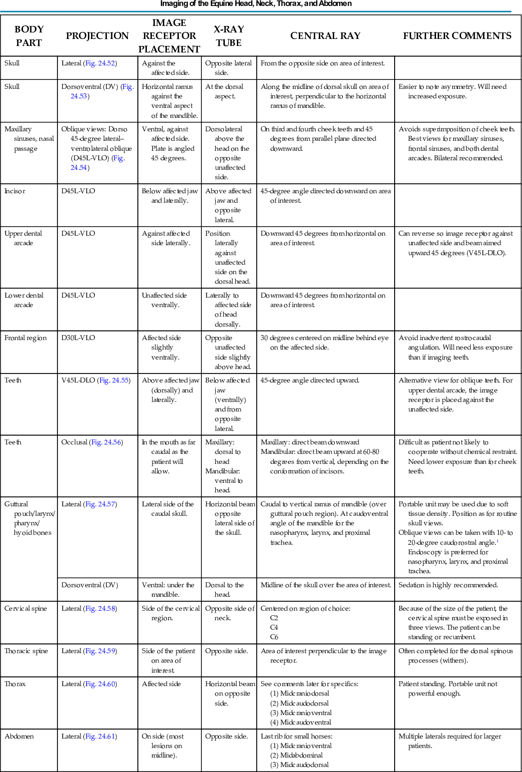
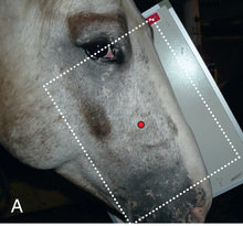
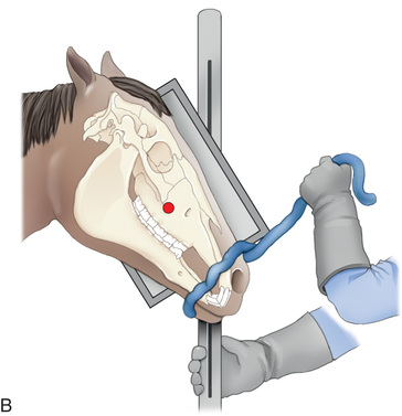
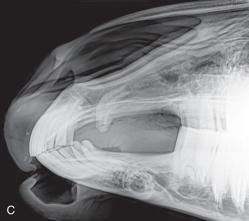
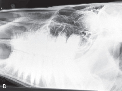
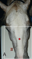
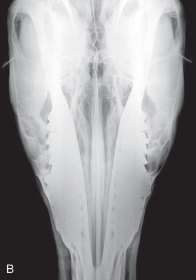
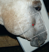
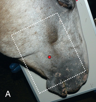
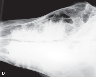
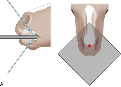
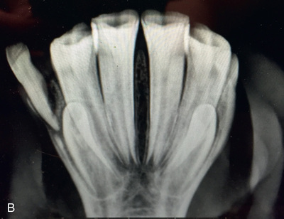
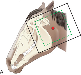
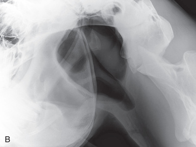
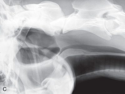
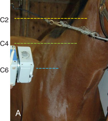
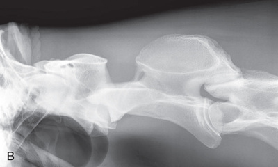
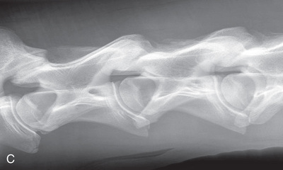
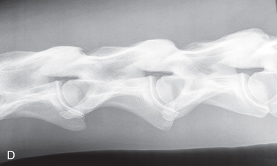
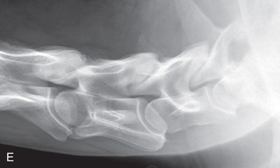
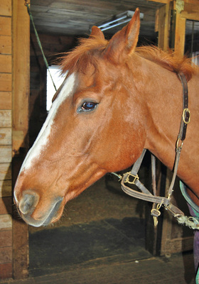
Skull Comments
- • The area of interest must be isolated because of the density of the skull and multiple areas of interest.
- • Keep the plate closest to the area of interest.
- • For best results, multiple views are recommended, including oblique views.
- • Removal of the halter is required to avoid artifacts. A commercial or homemade rope halter may be used. Inspect the rope for small metal clips, which are often present in manufactured rope products.
- • It is difficult to minimize movement of the skull. Sedation is crucial for most horses to obtain high-quality radiographs with minimal retakes. Resting the head on a surface such as hay bales or a stand and placing a cover over the patient's eyes may be helpful. Maintaining constant contact will keep the horse at ease and prevent reaction to changes in positioning.
- • The head is held without rotation. A lead rope placed under the chin and pulled upward may help stabilize the head.
- • Lowering the level of the head by extension or mild pressure allows for easier positioning of the unit and the image receptor.
- • Because of the weight of the x-ray unit, it may be difficult and awkward to hold it motionless at the level of the skull. The use of a stand or ceiling-mounted unit may prove more successful.
- • Flushing of the oral cavity is required to remove any foodstuffs to prevent artifacts.
- • If the patient is sedated, an oral gag may be used to improve the isolation of the selected arcade for oblique views.
- • An incisor block can be used for oblique views.
- • Barium or malleable metal may be used to mark draining facial tracts.
Technician Notes
The dental formula (see Chapter 22 for further explanation) of the horse is:
*Mares often do not have canine teeth; the first premolars, called wolf teeth, may not be present in either gender.
Cervical Spine Comments
- • Remember that the cervical spine is located in the ventral portion of the neck.
- • If the patient is in lateral recumbency, positioning devices are required to position the spine parallel to the table.
- • An increase in exposure factors is needed.
- • Flexed lateral, ventrodorsal, and oblique views are optional.
- • Consider placing radiopaque markers dorsal to the vertebrae for identification and repeat radiographs.
- • Collimate to the bones.
Thoracic Spine Comments
- • A lower-powered unit can be used to visualize the dorsal spinous processes (withers) of the thoracic spine (Fig. 24.59).
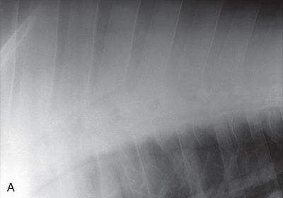
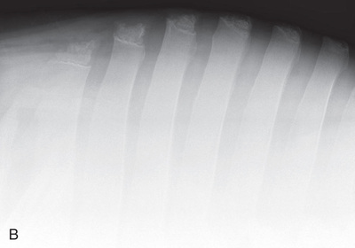 FIG. 24.59 Radiographs of the thoracic spine. Note the images of the body of the withers (A) and (B) the tips. (Courtesy Carolyn Bennet, Ontario Veterinary College, Veterinary Teaching Hospital, Diagnostic Imaging at University of Guelph, Ontario.)
 - • For the ventral portion of the thoracic vertebrae, a high-powered x-ray apparatus and a grid are needed.
- • Patient positioning is similar to that for radiographs of the thorax, except that the central ray is over the thoracic spine.
- • Mobile equipment may be used with smaller patients (i.e., foals).
Thorax Comments
- • High kVp with a grid is used.
- • The SID is usually increased to 200 cm (80 inches).
- • The caudodorsal region could be imaged with low-output equipment, short SID, and fast intensifying screens.
- • Radiographs are generally taken at full inspiration.
- • In a natural standing position, the elbows of a horse are superimposed over the cranial region of the thorax. Extend the forelimbs to prevent superimposition.
- • Center for the following regions in an average-size horse. Use a large image receptor and collimate to within the margins1 (Fig. 24.60):
- • Craniodorsal: 10 to 15 cm (4-6 inches) ventral to the most caudal point of the scapula.
- • Caudodorsal: 20 cm (8 inches) caudal to and 15 cm (6 inches) ventral to the most caudal part of the scapula.
- • Cranioventral: 15 cm (6 inches) caudal to the shoulder joint.
- • Caudoventral: 20 cm (8 inches) ventral to and 10 cm (4 inches) caudal to most caudal point of the scapula.
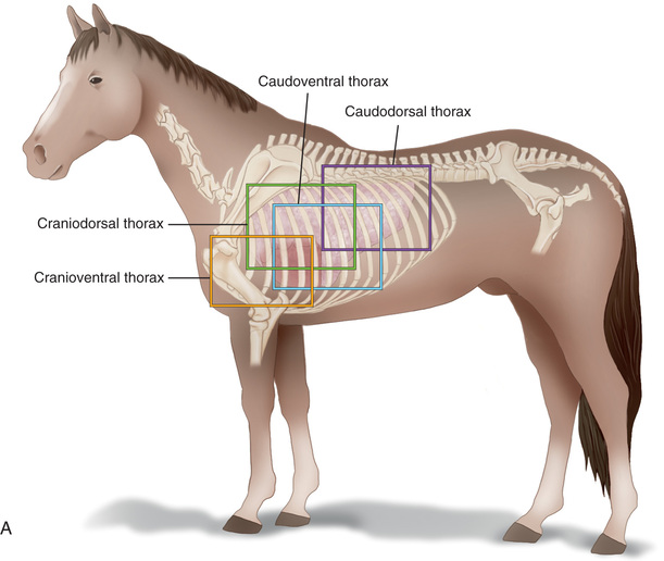
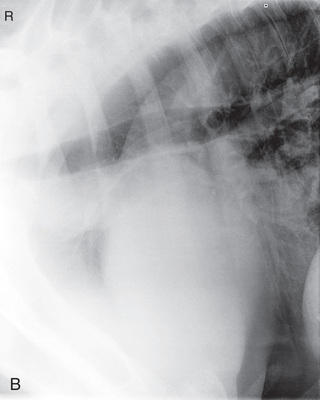
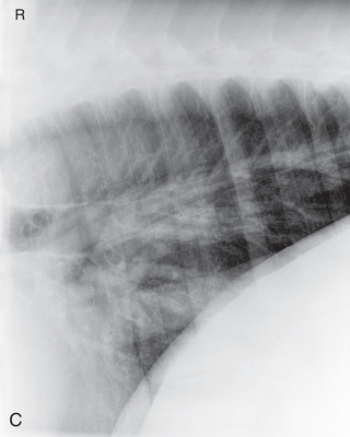
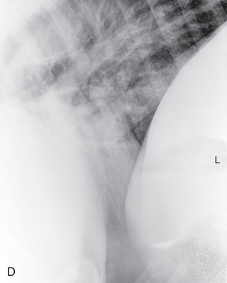
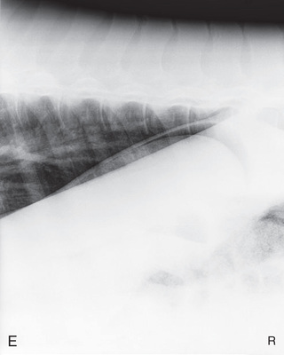 FIG. 24.60 A, Thorax areas of centering for the four main views. Lateral radiographs of the cranioventral thorax (B), craniodorsal thorax (C), caudoventral thorax (D), and caudodorsal thorax (E). (B to E courtesy Carolyn Bennet, Ontario Veterinary College, Veterinary Teaching Hospital, Diagnostic Imaging at University of Guelph, Ontario.)

Other Large-Animal Radiography
Bovine
Even if they are frequently handled, bovine patients have little to no experience of manipulation of their lower extremities, which poses a challenge to perform these radiographs. Maintaining image receptor placement close to the limb without proper restraint devices is almost impossible in most conditions. It is because of these challenges, as well as economic concerns, that radiographs are generally completed only in high-quality or high-producing livestock.
The use of stocks, ropes, and pulley, or ideally, a lift table, will aid in the production of quality radiographs of cattle. The use of stocks provides reduced mobility of the patient; however, they do not limit the mobility of the limbs. Securing the affected limb or, if weight-bearing, rigging an alternate limb through ropes, may be required. The use of a lift table enables the limbs to be secured in a motionless fashion and increases positioning options because the patient can be lifted and tilted off the ground. The lifting of the alternate limb may increase the safety of maneuvering around distal extremities. Sedation or rapid general anesthesia may be used with the bovine patient. The combined use of restraint devices and sedation can significantly increase the safety of personnel, equipment, and the patient for bovine radiographs. Care must be taken to consider the stage of gestation, if applicable, and the potential for recovery trauma.
Equipment requirements and positioning techniques for bovine radiography are the same as those for equine radiography. Handling restrictions may hinder the options and available positions. See Table 24.4 for the common views.
TABLE 24.4
| STRUCTURES | COMMON NAME | SPECIFIC TERMINOLOGYa | POSITIONb | CENTRAL RAY IS POSITIONED |
|---|---|---|---|---|
Digit/foot: P-III (distal phalanx, coffin bone) P-II (middle phalanx) P-I (proximal phalanx-pastern) Proximal interphalangeal joint (pastern joint) joint | DP (Standard) (Fig. 24.62B,C) | Dorsal 45-degree proximal–palmarodistal (D45Pr-PaDi) | Foot slightly forward on image receptor. | Perpendicular to foot axis at MSP (midsagittal plane) at area of interest with beam angled ~45 degrees to ground |
| Lateral (Standard) (Fig. 24.62D) | Lateromedial | On a block to elevate limb for P-III; resting on ground for other views. | 90 degrees lateral to MSP, parallel to ground on area of interest: coronary band for PIII | |
| Lateral-interdigit (Optional) | Lateromedial (mediolateral) with interdigital film | Receptor between digits. Easiest with patient in lateral recumbency but can be completed standing with foot raised. | 90 degrees laterally from MSP to radiograph the lateral claw. 90 degrees medially from MSP medially to radiograph the medial claw. | |
DLPMO (Optional) | Dorsoproximal 45-degree lateral–palmarodistomedial oblique (DPr45L-PaDiMO)/(DPr45M-PDiLO) | As for the lateral view for P-III. | 45 degrees to ground on the area of interest | |
| DMPLO (Optional) | Dorsoproximal 45-degree medial–palmarodistolateral oblique (DPr45M-PaDiLO) (DMPLO) | As for the DP view for P-II and P-I | 45 degrees lateral to MSP directed either laterally (DLPMO) or medially (DMPLO) | |
| Fetlock joint and proximal sesamoid bones | Dorsopalmar: DP (Standard) | Dorsoproximal-palmarodistal (DPr-PaDi) | Foot on ground, full weight-bearing and cassette against palmar aspect. | On MSP parallel to the ground, centered at the fetlock |
| Metacarpophalangeal/metatarsophalangeal articulation | Lateral (Standard) | Lateromedial extended (LM) | Foot on ground, full weight-bearing, and cassette against medial aspect. | 90 degrees laterally from MSP parallel to the ground directed toward the fetlock joint. |
| DLPMO (Optional) | Dorsoproximal 30-degree lateral–palmarodistomedial oblique (DPr30L-PaDiMO) (DLPMO) | Foot on ground, full weight-bearing, and cassette against medial aspect of palmar surface | 45 degrees lateral to MSP directed either laterally (DLPMO). | |
DMPLO (Optional) | Dorsoproximal 30-degree medial–palmarodistolateral oblique (DPr30M-PaDiLO) (DMPLO) | Foot on ground, full weight-bearing, and cassette against lateral aspect of palmar surface | Or medially (DMPLO) and parallel to ground on the fetlock joint or the proximal sesamoid bones. | |
| Carpusc | DP (Standard) | -Dorsoproximal-palmarodistal (DPr-PaDi) | Weight-bearing with limbs evenly on ground and cassette on palmar aspect of limb. | Parallel to the ground, centered on palpable intercarpal joint space; slightly lateral to MSP since legs are slightly rotated externally when standing. |
Lateral (Standard) | Lateromedial extended (LM) | Weight-bearing with limbs evenly on ground and cassette against medial aspect of limb. | 90 degrees lateral to MSP; parallel to ground just distal and dorsal to prominence of accessory carpal bone. | |
| Elbow joint | CdCr (Standard) | Caudoproximal-craniodistal- standing (CdPr-CrDi) | Weight-bearing with limbs evenly on ground and cassette against cranial aspect of joint at angle to the x-ray beam. | Caudal to joint; parallel to ground so beam perpendicular to radius. |
| Lateral (Standard) | Lateromedial standing (LM) | Weight-bearing with limbs evenly on ground; cassette against medial aspect of joint at angle to the x-ray beam. | 90 degrees lateral to MSP, parallel to ground on either the elbow joint or olecranon if required. | |
CrCd (Optional) | Cranioproximal-caudodistal standing (CrPr-CdDi) | Weight-bearing with limbs evenly on ground and cassette parallel against caudal aspect of olecranon and perpendicular to the lateral chest wall. | Directed upward at 20 degrees-30 degrees craniodistal to caudoproximal. | |
| Shoulder | Tangential oblique (Standard) | Caudomedial-Craniolateral obliqued | Weight-bearing with limb in normal position and image receptor placed vertically cranial to shoulder and pushed medially to ensure that the lateral tuberosity of the humerus will be imaged. | Caudally and is lateral and slightly dorsal to middle of thorax, angled downward, centered at the craniolateral aspect of the proximal humerus. |
Lateral (Optional since lateral recumbency required) | Mediolateral recumbent (ML) | In lateral recumbency with affected limb down and pulled cranially with the humeral head superimposed over the soft tissue of the neck. | Above the patient with the beam perpendicular to the ground and centered on the shoulder joint or area of interest. | |
| Tarsus | DP (two views) (Standard) | Horizontal dorsoplantar (1) 10 degrees dorsoproximal-plantarodistal (2) | For both views: full weight-bearing with digit pointing slightly outward so beam is not under the patient. image receptor against plantar aspect of tarsus parallel with calcaneus. | Dorsally and slightly laterally on MSP centered on palpable trochlea. For view 1: beam is parallel to ground (shows tarsometatarsal joint space) For view 2: angle 10 degrees downward in dorsoproximal to plantarodistal angle (for intertarsal joint space). |
| Lateral (Standard) | Lateromedial | Weight-bearing with limbs evenly on ground and cassette against medial aspect of limb. | 10 cm (4 inches) distal to point of hock. | |
| Stifle | Caudocranial CdCr (Standard) | Caudoproximal-craniodistal standing (CdPr-CrDi) | Weight-bearing with limbs evenly on ground and vertical cassette against cranial aspect of patella at right angle to body wall, placed as far proximal and pushed as far medially as abdomen permits. | Caudal to the joint and directed downward to obtain a “tunnel” view of the distal femur. |
| Lateral (Standard) | Lateromedial | Weight-bearing with limbs evenly on ground and cassette against medial aspect of joint. | Laterally, parallel to the ground and centered distal and caudal to the patella. | |
| Lateral patella (Optional) | Lateromedial (LM) patella | Weight-bearing with limbs evenly on ground and cassette against medial aspect of patella further proximally and cranially than for regular LM view. | Parallel to the ground and centered on the patella. |
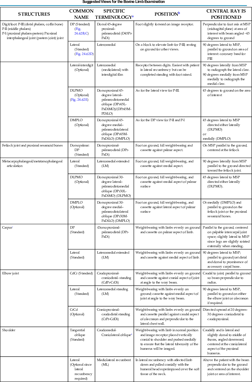
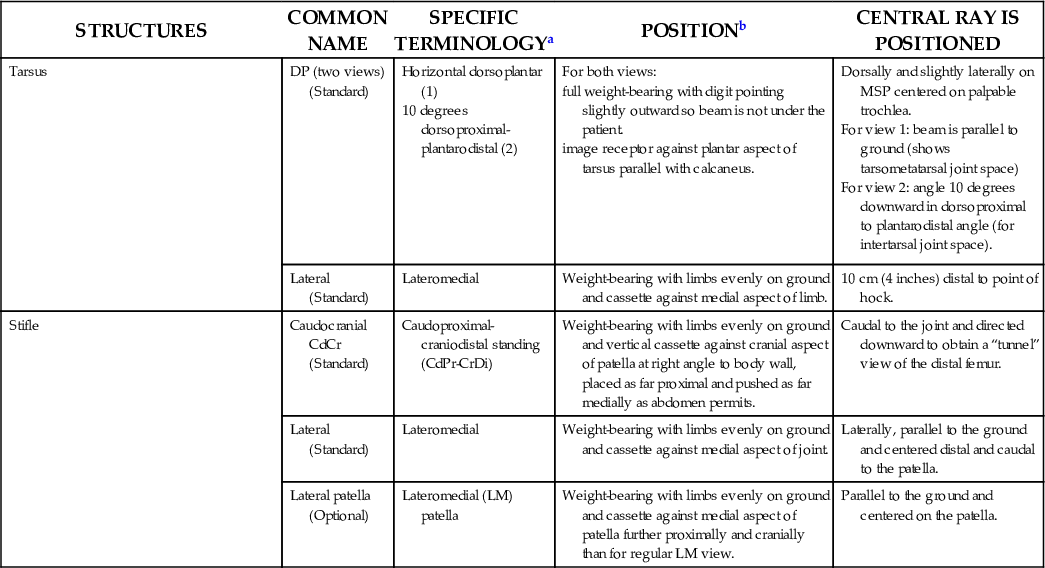
aPalmar(o) is used with the understanding that plantar(o) can be substituted when referring to the hind limb.
bFurther specifications with preparation and positioning for the digit: Before a digit radiograph is taken in the bovine patient, the interdigital space and both claws should be cleansed thoroughly and lightly trimmed. If this step is not taken, false images or shadows may mask abnormalities present in the claws. The digits can be viewed radiographically using four angles or projections.6
cOptional views for the carpus include the lateromedial flexed, dorsolateral-palmaromedial oblique (DLPMO), and dorsomedial-palmarolateral oblique (DMPLO). The oblique views are also possible for the elbow joint.
dUsually only the area of the acromion process of the scapula and lateral tubercles of the humerus are visualized on the oblique views and not the character of the shoulder joint. There is extensive scatter radiation due to increased soft tissue. The oblique view is best combined with the lateral view in a recumbent patient.
Further studies of the bovine include pelvis (dorsal recumbency only with hind limbs extended laterally as much as possible); the head (please see the equine for similar positioning); and the spine, thorax, and abdomen (also see as per the equine patient).
Data from Morgan JP: Techniques of Veterinary Radiography, Ames, IA, 1993, Iowa State University Press.
- Center: On the area of interest.
- Include: Up to one-third of the bones proximal and distal for a joint; for a bone, include the joints proximal and distal.
- Collimate: Tightly to include the area of interest, ensuring that labels are included and borders are visible.
Pelvis, skull, spine, thorax, and abdomen radiographs are completed much like those in horses. In the case of a small calf, radiographs may be performed in the clinic with use of positioning and techniques similar to those used for a large dog. A mobile x-ray machine can be used to take thoracic or abdominal radiographs in a small calf (Fig. 24.62).
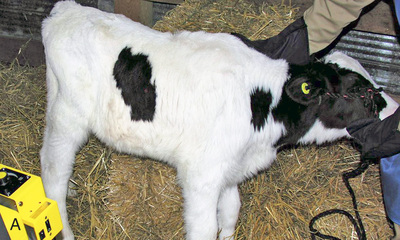
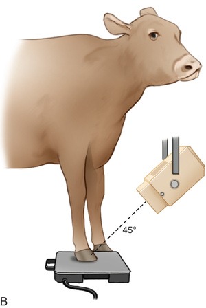
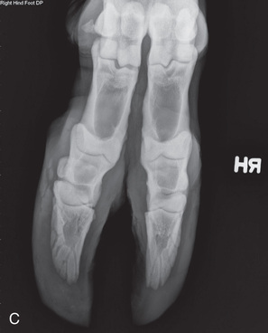
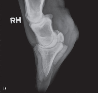
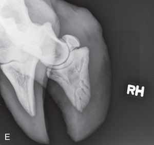
Ovine/Caprine/Porcine
Small ruminant patients (sheep/goats) and swine can be radiographed much like small animals (Fig. 24.63). Because they can be easily transported, small ruminant patients are often radiographed within the clinic setting.
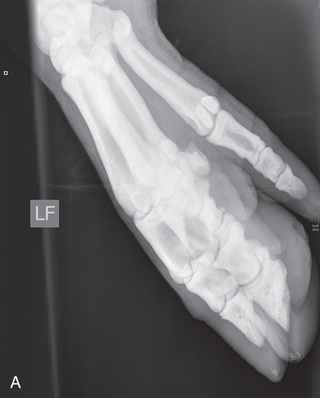
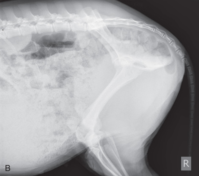
Because of their minimal handling experience, however, care must be taken to prevent injury due to patient response to fear (i.e., thrashing of limbs). If the patient is horned, special precautions to prevent injury to staff must be taken. Sedation is recommended to produce quality radiographs in an efficient manner.
The fleece of the ovine patient is dense and may contain dirt and debris (i.e., twigs, clumps of mud/stones). Before imaging, carefully inspect for and remove debris that may produce artifacts within the image.
Technician Notes
Think of positioning cattle for x-rays as being similar to horses with exceptions due to limb angles or anatomy; positioning of sheep and swine is similar to the dog. Restraint is different for all species.
Alternate Modality Images
It is beyond the scope of this text to discuss alternate modalities (Fig. 24.64) in this edition. Additional imaging, such as nuclear scintigraphy, infrared thermal imaging, and MRI, show more features for diagnosis but are considerably more expensive than imaging with the use of x-radiation.
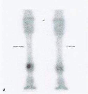
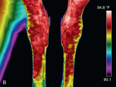
Fig. 24.65 is a mystery radiograph. Review it and answer the question presented with it.
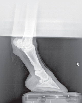
 Key Points
- 1. Patience, planning, proper preparation, and knowledge of anatomy and directional terms are all required for diagnostic large-animal radiographs.
- 2. Large animals generally stand for radiography, which necessitates the use of a horizontal beam.
- 3. Radiation, patient, and human safety need to be kept in mind at all times.
- 4. Because of the unique anatomy of the equine limb, a minimum of four views is required: dorsopalmar/dorsoplantar, lateromedial, and two oblique views, one on either side of the midsagittal plane taken between the DP and lateromedial positions.
- 5. If joints are to be examined, further positions may include a flexed lateral, skyline, or flexor view.
- 6. The same principles of radiography apply to all species. Thus the angle of the beam is always perpendicular to the area of interest. In the equine patient, the angle of the beam to the ground for dorsopalmar/dorsoplantar and oblique radiographs may vary according to the foot trimming and anatomy. For lateromedial views, the beam is always parallel to the ground.
- 7. Standard radiographs for cloven-footed large animals are generally the dorsopalmar/dorsoplantar and lateromedial views with occasional oblique projections for joints.
Review Questions
1. Safety is a priority when taking radiographs. To keep personnel away from the central ray when the metacarpus of large animals is being radiographed, you should:
b. Use a foot block with a cassette slot
c. Use a cassette holder with a clamp and long handle
2. When viewing a DMPLO radiograph of the equine fetlock, you should place the image on the viewer so that the proximal cannon bone is positioned:
a. Down with the dorsal aspect to your left
b. Up with the dorsal aspect to your left
c. Up with the dorsal aspect to your right
d. Down with the dorsal aspect to your right
3. To prevent air artifacts when radiographing the equine foot, it is best to use:
4. The dorsal 65-degree proximal–palmarodistal oblique (D65Pr-PaDiO) view of the distal phalanx means that the beam is angled:
a. To the ground, 65 degrees palmaroproximal
b. 65 degrees from the MSP and to the ground
c. 65 degrees to the limb, dorsoproximal
d. To the ground 65 degrees dorsoproximal
5. The dorsal 65-degree proximal–palmarodistal oblique (D65Pr-PaDiO) view of the digit is also known as a:
6. A human wrist is equivalent to the equine:
b. Metacarpal interphalangeal joint
7. For the upright pedal route of the navicular bone the foot will be:
a. Pointed on a block with the beam parallel to the ground
b. Placed flat on the tunnel cassette with the beam angled
c. Placed flat on a block with the beam angled to the ground
d. Placed flat on the tunnel cassette with the beam parallel to the ground
8. For a true DP view of the navicular bone, you need to include the:
d. Coffin bone, navicular, and long pastern
9. The descriptive terminology for a DLPMO is:
a. Dorsal 45-degree proximal lateral–palmarodistomedial oblique
b. Dorsoproximal 45-degree lateral–palmarodistomedial oblique
c. Dorsoproximal 45-degree medial–palmarodistolateral oblique
d. Dorso 45-degree proximal medial–palmarodistolateral oblique
10. You are preparing to image the DMPLO of the digit of a Thoroughbred. The image receptor should be placed at the _______ oblique aspect of the limb and the beam directed dorsal 65-degree proximal and _____________
a. lateral; 45-degree at the lateral
b. lateral; 45-degree at the medial
c. medial; 45-degree at the medial
d. medial; 45-degree at the lateral
11. The veterinarian will request that you complete the DMPLO view of the digit to visualize the __________ wing of the coffin bone, which will appear ____________ on the image.
a. lateral; smaller and denser
b. lateral; larger and less dense
d. medial; larger and less dense
12. To image the fetlock, the image receptor should be placed against the:
a. Medial aspect of the limb, perpendicular to the ground for a flexed lateral view
b. Medial aspect of the limb, perpendicular to the ground for a DP view
c. Medial aspect of the limb, parallel with the ground for a flexed lateral view
d. Lateral side of the limb, perpendicular to the ground for a lateromedial view
a. First and fifth metacarpus/metatarsus
b. Second and fourth metacarpus/metatarsus
c. Second and third metacarpus/metatarsus
d. Third and fourth metacarpus/metatarsus
14. You are required to complete a lateromedial view of the metacarpals of an Arabian. The central ray is:
a. On the medial aspect and angled 90 degrees from the MSP
b. Angled to the ground and 90 degrees from the MSP
c. Parallel to the ground and angled 90 degrees from the MSP
d. Parallel to the ground and angled 45 degrees from the MSP
15. To position for the craniocaudal view of the elbow, place the image receptor on the:
b. Plantar aspect of the joint
c. Cranial aspect of the joint
16. Oblique views are necessary for an equine dental survey to avoid:
a. Increased amount of soft tissue on the head
b. Superimposition of the guttural pouch
c. Superimposition of the frontal sinuses
d. Superimposition of the opposite arcade
17. Pelvic radiographs may be contraindicated in equine patients with a pelvic injury because:
a. Anesthesia poses a risk to the equine patient
b. Patient recovery may cause additional injury
c. Pelvic radiographs are often unsuccessful
d. Pelvic radiographs are never contraindicated
18. The SID for large animals is generally:
a. The same as for small animals
c. Shorter than for small animals
d. Longer than for small animals
19. You are required to complete a carpus DP view for a Holstein cow (dairy). You should position the central ray:
a. Parallel to the ground and slightly lateral to the MSP
b. Parallel to the ground on the MSP
c. Parallel to the ground slightly medial to the MSP
d. At a slight angle to the ground on the MSP
20. The view that is completed for cattle but not performed on an equine P3 is the:
b. Dorsal 45-degree proximal–palmarodistal view
c. Lateromedial (mediolateral) view with interdigital film
d. Dorsal 45-degree lateral–palmaromedial oblique
Chapter Review Question answers are located in the Instructor Resources on Evolve and can be provided to students at the discretion of the Instructor.