Scatter Control
OBJECTIVES
- 1. Define all the key terms in this chapter.
- 2. State all the important relationships in this chapter.
- 3. Explain how scatter radiation affects radiographic images.
- 4. State the purpose of beam-restricting devices.
- 5. Describe each type of beam-restricting device.
- 6. State the purpose of automatic collimators or positive beam-limiting devices.
- 7. Describe the purpose of a radiographic grid.
- 8. Describe the construction of grids, including the different types of grid patterns, dimensions, and grid focus.
- 9. Calculate grid ratio.
- 10. List the various types of stationary grids and describe the function and purpose of a moving grid.
- 11. Demonstrate the use of the grid conversion formula.
- 12. Describe the different types of grid alignment errors that can occur to cause grid cutoff.
- 13. Identify the factors to be considered in using a grid.
- 14. Recognize how beam restriction and the use of grids affect patient radiation exposure.
- 15. Explain the air gap technique and describe its use.
KEY TERMS
air gap technique; aperture diaphragm; automatic collimator; beam-restricting device; beam restriction; Bucky; Bucky factor; collimation; collimator; cone; convergent line; convergent point; crossed grid; crosshatched grid; cylinder; focal distance; focal range; focused grid; grid; grid cap; grid cassette; grid conversion factor (GCF); grid cutoff; grid focus; grid frequency; grid pattern; grid ratio; interspace material; linear grid; long dimension; moiré effect; nonfocused grid; parallel grid; positive beam-limiting device; short dimension; wafer grid
Controlling the amount of scatter radiation produced in a patient and ultimately reaching the image receptor (IR) is essential for creating a good-quality image. Scatter radiation is detrimental to radiographic quality because it adds unwanted exposure (fog) to the image without adding any patient information.
Digital IRs are sensitive to lower-energy levels of radiation such as scatter, which results in increased fog in the image and decreases radiographic contrast. However, image contrast can be computer manipulated by changing the window width. Increased scatter radiation, produced within the patient and the higher-energy scatter exiting the patient, affects the exposure to the patient and anyone within close proximity. The radiographer must act to minimize the amount of scatter radiation reaching the IR.
Beam-restricting devices and radiographic grids are tools that the radiographer can use to limit the amount of scatter radiation reaching the IR. Beam-restricting devices decrease the x-ray-beam field size and the amount of tissue irradiated, thereby reducing the amount of scatter radiation produced. Radiographic grids are used to improve radiographic image quality by absorbing scatter radiation exiting the patient, thereby reducing the amount of scatter reaching the IR. It should be noted that grids do nothing to prevent scatter production; they merely reduce the amount of scatter reaching the IR after scatter radiation is produced.
SCATTER RADIATION
Scatter radiation, as described in Chapter 3, is primarily the result of Compton interactions, in which an incoming x-ray photon loses energy and changes direction. Two major factors affect the amount and energy of scatter radiation exiting the patient: kilovoltage peak (kVp) and the volume of irradiated tissue. The volume of irradiated tissue depends on the thickness of the part and the x-ray-beam field size. Increasing the volume of irradiated tissue results in increased scatter production because there are more atoms available for Compton interactions. In addition, using a higher kVp increases x-ray transmission and reduces its overall absorption (photoelectric interactions); however, higher kVp increases the percentage of Compton interactions and the energy of scatter radiation exiting the patient. Using higher kVp or increasing the volume of irradiated tissue results in increased scatter radiation exiting the patient.
BEAM RESTRICTION
It is the responsibility of the radiographer to limit the x-ray-beam field size to the anatomic area of interest. Beam restriction serves two purposes: limiting patient exposure and reducing the amount of scatter radiation produced within the patient.
The unrestricted primary beam is cone shaped and projects a round field onto the patient and IR (Fig. 7-1). If not restricted in some way, the primary beam goes beyond the boundaries of the IR, resulting in unnecessary patient exposure. Any time the x-ray field extends beyond the anatomic area of interest, the patient receives unnecessary exposure. Limiting the x-ray-beam field size is accomplished with a beam-restricting device. Located just below the x-ray tube housing, the beam-restricting device changes the shape and size of the primary beam.
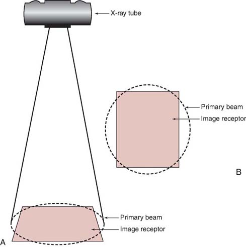
FIG. 7-1 The unrestricted primary beam is cone shaped, projecting a circular field. A, Side view. B, View from above.
The terms beam restriction and collimation are used interchangeably; they refer to a decrease in the size of the projected radiation field. The term collimation is used more often than the term beam restriction because collimators are the most popular type of beam-restricting device. Increasing collimation means decreasing the field size, and decreasing collimation means increasing the field size (Fig. 7-2).

FIG. 7-2 A, Full view of the abdomen with decreased collimation when compared with B. B, Increased collimation of the abdominal region to image the lumbar spine. (From Bontrager K, Lapignano J: Textbook of Radiographic Positioning and Related Anatomy, ed 7, St. Louis, 2010, Elsevier.
BEAM RESTRICTION AND SCATTER RADIATION
In addition to decreasing the patient dose, beam-restricting devices reduce the amount of scatter radiation produced within the patient and reduce the amount of scatter to which the IR is exposed, thereby increasing radiographic contrast. The relationship between collimation (field size) and the quantity of scatter radiation is illustrated in Fig. 7-3. As previously stated, collimation means decreasing the size of the projected x-ray field; hence, increasing collimation means decreasing x-ray field size, and decreasing collimation means increasing x-ray field size.
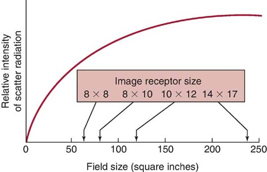
FIG. 7-3 As field size increases, the relative quantity of scattered radiation increases.
Collimation and Contrast
Because collimation decreases the x-ray-beam field size, less scatter radiation is produced within the patient, and hence, less scatter radiation reaches the IR. As described in Chapter 3, this affects the radiographic contrast.
Compensating for Collimation
Increasing the collimation decreases the volume of tissue irradiated, the amount of scatter radiation produced, the number of photons that strike the patient, and the number of x-ray photons that reach the IR to produce the latent image. As a result, the exposure-technique factors (kVp, milliamperage-seconds [mAs], or both) may need to be increased when increasing collimation to maintain exposure to the IR.
It has been recommended that significant collimation requires the mAs to be increased by 30% to 50% to compensate for the decrease in IR exposure. Post-exposure electronic masking or cropping of the displayed digital image is a feature available at the radiographer's workstation. However, post-exposure electronic masking should never replace pre-exposure collimation because it does not reduce scatter production, improve image contrast, or reduce patient radiation exposure.
Important relationships regarding the restriction of the primary beam are summarized in Table 7-1.
Table 7-1
| Increased Factor | Result |
|---|---|
| Collimation | Patient dose decreases |
| Scatter radiation decreases | |
| Radiographic contrast increases | |
| Exposure to the image receptor decreases | |
| X-ray field size | Patient dose increases |
| Scatter radiation increases | |
| Radiographic contrast decreases | |
| Exposure to the image receptor increases |
TYPES OF BEAM-RESTRICTING DEVICES
Several types of beam-restricting devices, which differ in sophistication and utility, are available. Most beam-restricting devices are made of metal or a combination of metals that readily absorb x-rays.
Aperture Diaphragms
The simplest type of beam-restricting device is the aperture diaphragm. An aperture diaphragm is a flat piece of lead (diaphragm) that contains a hole (aperture). Commercially made aperture diaphragms are available (Fig. 7-4), or hospitals can make their own for purposes specific to a radiographic unit. Aperture diaphragms are easy to use; they are placed directly below the x-ray tube window. An aperture diaphragm can be made by cutting rubberized lead into the size needed to create the diaphragm and cutting a hole of the appropriate shape and size into the center to create the aperture.
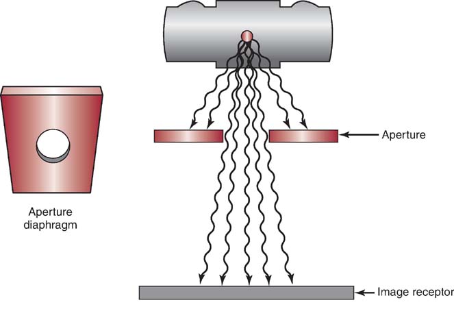
FIG. 7-4 Commercially made aperture diaphragm.
Although the size and shape of the aperture can be changed, the aperture cannot be adjusted from the designed size, and therefore, the projected x-ray field size is not adjustable. In addition, because of the aperture's proximity to the radiation source (focal spot), a large area of unsharpness surrounds the radiographic image (Fig. 7-5). Although aperture diaphragms are still used in some applications, their use is not as widespread as other types of beam-restricting devices.
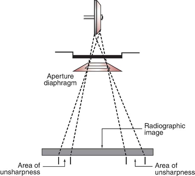
FIG. 7-5 Radiographic image unsharpness using an aperture diaphragm.
Cones and Cylinders
Cones and cylinders are shaped differently (Fig. 7-6), but they have many similar attributes. A cone or cylinder is essentially an aperture diaphragm that has an extended flange attached to it. The flange can vary in length and can be shaped as either a cone or a cylinder. The flange can also be made to telescope, increasing its total length (Fig. 7-7). Like aperture diaphragms, cones and cylinders are easy to use but generally not in use today. They slide onto the tube, directly below the window. Cones and cylinders limit the unsharpness surrounding radiographic images more than aperture diaphragms do, with cylinders accomplishing this task slightly better than cones (Fig. 7-8). However, they are limited in terms of available sizes, and they are not interchangeable among tube housings. Cones have a disadvantage compared with cylinders: if the angle of the flange of the cone is greater than the angle of divergence of the primary beam, the base plate or aperture diaphragm of the cone is the only metal restricting the primary beam. Therefore, cylinders generally were more useful than cones. Cones and cylinders are almost always made to produce a circular projected field and were advantageously used for some radiographic procedures (Fig. 7-9).
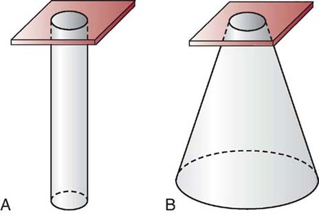
FIG. 7-6 A, Cylinder. B, Cone.
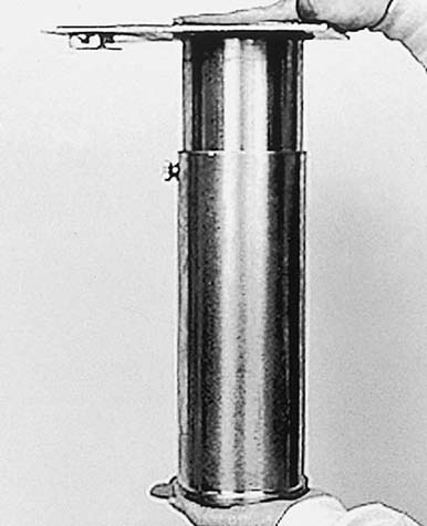
FIG. 7-7 Telescoping cylinder. (From Mosby's Radiographic Instructional Series: Radiographic Imaging, St. Louis, 1998, Mosby.)
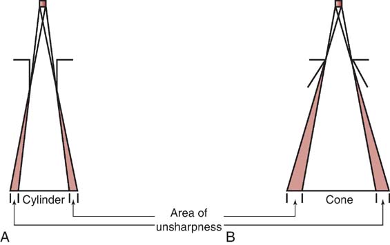
FIG. 7-8 A cylinder (A) is better at limiting unsharpness than a cone (B).
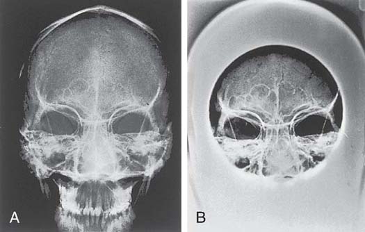
FIG. 7-9 Radiograph of the frontal and maxillary sinuses not using a cone (A) and using a cone (B). (From Mosby's Radiographic Instructional Series: Radiographic Imaging, St. Louis, 1998, Mosby.)
Collimators
The most sophisticated, useful, and accepted type of beam-restricting device for radiography today is the collimator. Beam restriction accomplished with the use of a collimator is referred to as collimation. The terms collimation and beam restriction are used interchangeably.
A collimator has two or three sets of lead shutters (Fig. 7-10). Located immediately below the tube window, the entrance shutters limit the x-ray beam much as the aperture diaphragm would. One or more sets of adjustable lead shutters are located 3 to 7 inches (8–18 cm) below the tube. These shutters consist of longitudinal and lateral leaves or blades, each with its own control. This design makes the collimator adjustable in terms of its ability to produce projected x-ray fields of varying sizes. The x-ray field shape produced by a collimator is always rectangular or square unless an aperture diaphragm, cone, or cylinder is slid in below the collimator. Collimators are equipped with a white light source and a mirror to project a light field onto the patient. This light is intended to accurately indicate where the primary x-ray beam will be projected during exposure. In case of failure of this light, an x-ray field measurement guide (Fig. 7-11) is present on the front of the collimator. This guide indicates the projected field size on the basis of the adjusted size of the collimator opening at source-to-image-receptor distances (SIDs). This guide helps to ensure that the radiographer does not open the collimator to produce an x-ray field that is larger than the IR. Another problem that may occur is the lack of accuracy of the light field. The mirror that reflects the light down toward the patient or the light bulb itself could be slightly out of position, projecting a light field that inaccurately indicates where the primary beam will be projected. There is a means of testing the accuracy of this light field and the location of the center of the projected beam (Box 7-1).
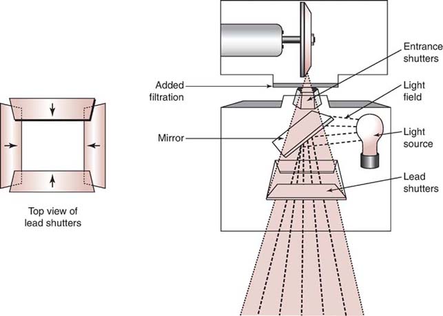
FIG. 7-10 Collimators have two sets of lead shutters that are used to change the size and shape of the primary beam.

FIG. 7-11 The x-ray field measurement guide on the front of a collimator.
A plastic template with crosshairs is affixed to the bottom of the collimator to indicate where the center of the primary beam (central ray) will be directed. This template is of great assistance to the radiographer in accurately centering the x-ray field to the patient.
Automatic Collimators
An automatic collimator, also called a positive beam-limiting device, automatically limits the size and shape of the primary beam to the size and shape of the IR. For a few years, automatic collimators were required by the US federal law on all new radiographic installations. This law has since been rescinded, and automatic collimators are no longer a requirement on any radiographic equipment. However, they are still widely used. Automatic collimators mechanically adjust the primary beam size and shape to the size and placement of the IR when the IR is placed in the Bucky tray, which is located just below the tabletop and behind the front of the upright unit. In newer direct radiography units with a single IR, automatic collimation may occur when the anatomic area to be imaged is selected. For example, if an anteroposterior (AP) shoulder is selected, the collimator may automatically adjust to an 8 × 12-inch (20 × 30-cm) x-ray field size, but if an AP lumbar spine is selected, the collimator will automatically adjust to a 10 × 14-inch (25 × 35-cm) x-ray field size.
Automatic collimation makes it difficult for the radiographer to increase the size of the primary beam to a field larger than that of the IR, which would result in increasing the patient's radiation exposure. Positive beam-limiting devices were seen as a way to protect patients from overexposure to radiation; however, it should be noted that automatic collimators have an override mechanism that allows the radiographer to disengage this feature.
RADIOGRAPHIC GRIDS
The radiographic grid was invented in 1913 by Gustave Bucky and continues to be the most effective means for limiting the amount of scatter radiation that reaches the IR. Approximately ¼ inch thick and ranging from 8 × 10 inches (20 × 25 cm) to 17 × 17 inches (43 × 43 cm), a grid is a device consisting of very thin lead strips with radiolucent interspaces intended to absorb scatter radiation emitted from the patient. Placed between the patient and the IR, grids are invaluable in the practice of radiography. They work well to improve radiographic contrast; however, they possess certain drawbacks. As discussed later in this chapter, using a grid requires additional mAs, resulting in a higher patient dose. Therefore, grids are typically used only when the anatomic part is 10 cm (4 inches) or greater in thickness and more than 60 kVp is needed for the examination.
As scatter radiation leaves the patient, a significant amount is directed toward the IR. As previously stated, scatter radiation is detrimental to image quality because it adds unwanted exposure (fog) to the IR without adding any radiographic information. Scatter radiation decreases radiographic contrast. Ideally, grids would absorb, or clean up, all scattered photons directed toward the IR and would allow all transmitted photons emitted from the patient to pass to the IR. Unfortunately, this does not happen (Fig. 7-12). When used properly, however, grids can greatly increase the contrast of the radiographic image.
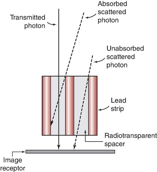
FIG. 7-12 Ideally, grids would absorb all scattered radiation and allow all transmitted photons to reach the image receptor (IR). In reality, however, some scattered photons pass through to the IR, and some transmitted photons are absorbed.
Grid Construction
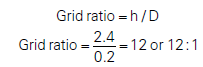
Grids contain thin lead strips or lines that have a precise height, thickness, and space between them. Radiolucent interspace material separates the lead lines. Interspace material typically is made of aluminum. An aluminum front and back panel cover the lead lines and interspace material of the grid. Grid construction can be described by grid frequency and grid ratio. Grid frequency expresses the number of lead lines per unit length, in inches, centimeters, or both. Grid frequencies can range in value from 25 to 80 lines/cm (63–200 lines/inch). A typical value for grid frequency might be 40 lines/cm (100 lines/inch). Another way of describing grid construction is by its grid ratio. Grid ratio is defined as the ratio of the height of the lead strips to the distance between them (Fig. 7-13). Grid ratio can also be mathematically expressed as follows:
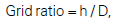
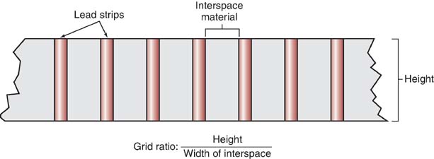
FIG. 7-13 Grid ratio is the ratio of the height of the lead strips to the distance between them.
in which h is the height of the lead strips and D is the distance between them.
MATHEMATICAL APPLICATION
Calculating Grid Ratio
What is the grid ratio when the lead strips are 2.4 mm high and separated by 0.2 mm?
Grid ratios range from 4:1 to 16:1. High-ratio grids remove, or clean up, more scatter radiation than lower-ratio grids having the same grid frequency, thereby further increasing radiographic contrast.
There is a relationship among grid ratio, grid frequency, and the amount of lead content (measured in mass per unit area). Increasing the grid ratio for the same grid frequency increases the amount of lead content and therefore increases scatter absorption.
Information about a grid's construction is contained on a label placed on the tube side of the grid. This label usually states the type of interspace material used, grid frequency, grid ratio, grid size, and information about the range of SIDs that can be used with the grid. The radiographer should read this information before using the grid because these factors influence grid performance, exposure technique selection, grid alignment, and image quality.
Grid Pattern
Grid pattern refers to the linear pattern of the lead lines of a grid. Two types of grid patterns exist: linear and crossed or crosshatched. A linear grid has lead lines that run in only one direction (Fig. 7-14). Linear grids are the most popular grid pattern because they allow angulation of the x-ray tube along the length of the lead lines. A crossed grid or crosshatched grid has lead lines that run at right angles to one another (Fig. 7-15). Crossed grids remove more scattered photons than linear grids because they contain more lead strips, oriented in two directions. However, applications are limited with a crossed grid because the x-ray tube cannot be angled in any direction without producing grid cutoff (i.e., absorption of the transmitted x-rays). Grid cutoff is undesirable and is discussed later in this chapter.
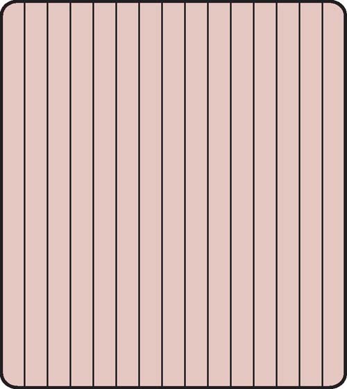
FIG. 7-14 Linear grid pattern.
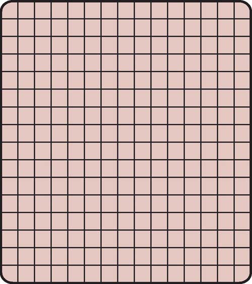
FIG. 7-15 Crossed or crosshatched grid pattern.
Grid Focus
Grid focus refers to the orientation of the lead lines relative to one another. A parallel grid or nonfocused grid has lead lines that run parallel to one another (Fig. 7-16). Parallel grids are used primarily in fluoroscopy and mobile imaging. A focused grid has lead lines that are angled, or canted, to approximately match the angle of divergence of the primary beam (Fig. 7-17). The advantage of focused grids compared with parallel grids is that focused grids allow more transmitted photons to reach the IR. As seen in Fig. 7-18, transmitted photons are more likely to pass through a focused grid to reach the IR than they are to pass through a parallel grid.
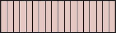
FIG. 7-16 Parallel, or nonfocused, type of grid.

FIG. 7-17 Focused type of grid.
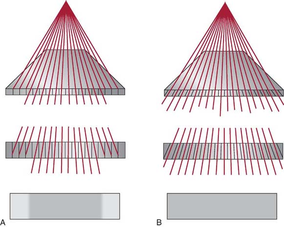
FIG. 7-18 Comparison of transmitted photons passing through a parallel grid (A) and a focused grid (B).
As seen in Fig. 7-19, if imaginary lines were drawn from each of the lead lines in a linearly focused grid, these lines would meet to form an imaginary point called the convergent point. If points were connected along the length of the grid, they would form an imaginary line called the convergent line. Both the convergent line and the convergent point are important because they determine the focal distance of a focused grid. The focal distance (sometimes referred to as grid radius) is the distance between the grid and the convergent line or point, and it is important because it is used to determine the focal range of a focused grid. The focal range is the recommended range of SIDs that can be used with a focused grid. The convergent line or point always falls within the focal range (Fig. 7-20). For example, a common focal range is 36 to 42 inches (90–105 cm), with a focal distance of 40 inches (100 cm). Another common focal range is 66 to 74 inches (165–185 cm), with a focal distance of 72 inches (180 cm). Because the lead lines in a parallel grid are not angled, they have a focal range extending from a minimum SID to infinity.
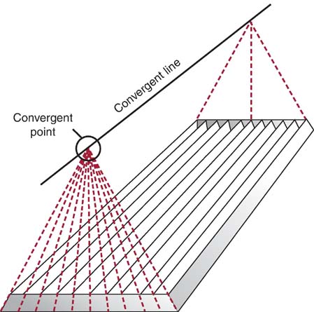
FIG. 7-19 Imaginary lines drawn above a linear focused grid from each lead strip meet to form a convergent point; the points form a convergent line.

FIG. 7-20 The convergent line or point of a focused grid falls within a focal range.
Types of Grids
Grids are available for use by the radiographer in several forms and can be stationary or moving. Stationary, nonmoving grids include the wafer grid, grid cassette, and grid cap. A wafer grid matches the size of the cassette and is used by placing it on top of the IR. Wafer grids typically are taped to the IR to prevent them from sliding during the radiographic procedure. A grid cassette is an IR that has a grid permanently mounted on its front surface. A grid cap contains a permanently mounted grid and allows the IR to slide in behind it; this is useful because the grid is secure, and many IRs can be interchanged behind the grid before processing the CR images.
Stationary and Reciprocating Grids
When grids are stationary, it is possible to examine them closely and see the grid lines on the radiographic image. Slightly moving the grid during the x-ray exposure blurs the grid lines (motion unsharpness), rendering them less visible.
Moving or reciprocating grids are part of the Bucky, more accurately called the Potter–Bucky diaphragm. Located directly below the radiographic tabletop, the grid is found just above the tray that holds the IR. Grid motion is electrically controlled by the x-ray exposure switch. The grid moves slightly back and forth in a lateral direction over the IR during the entire exposure. These grids typically have dimensions of 17 × 17 inches (43 × 43 cm) so that a 14 × 17 inches (35 × 43 cm) IR can be positioned under the grid either lengthwise or crosswise, depending on the examination requirements.
Long-Dimension versus Short-Dimension Grids
Linear grids can be constructed with either long dimension or short dimension. A long-dimension linear grid has lead strips running parallel to its long axis, whereas a short-dimension linear grid has lead strips running perpendicular to its long axis (Fig. 7-21). For example, whereas a 14 × 17-inch (35 × 43-cm) long-dimension grid has 17-inch (43-cm)-long lead strips, a short-dimension grid has 14-inch (35-cm)-long lead strips. A short-dimension grid may be useful for examinations when it is difficult to correctly center or angle the central ray for the long-dimension grid (e.g., imaging a decubitus or stretcher chest in the crosswise IR direction).
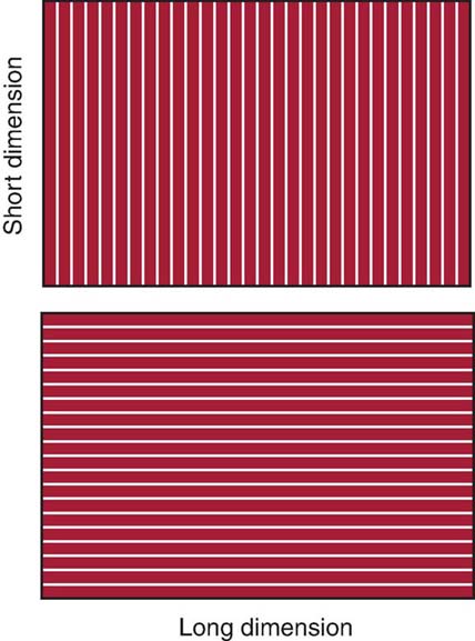
FIG. 7-21 A long-dimension grid has lead strips running parallel to the long axis of the grid. A short-dimension grid has lead strips running perpendicular to the long axis of the grid. (From Johnston JN, Fauber TL: Essentials of Radiographic Physics and Imaging, ed 2, St. Louis, 2016, Mosby.)
Grid Performance
The purpose of using grids in radiography is to increase radiographic contrast. In addition to improving contrast by cleaning up scatter, grids reduce the total amount of x-rays reaching the IR. The better the grid is at absorbing scattered photons, such as with a higher-ratio grid, the fewer the photons reach the IR. To compensate for this reduction, additional mAs must be used to maintain exposure to the IR. The grid conversion factor (GCF), or Bucky factor, can be used to determine the required adjustment in mAs when changing from using a grid to nongrid (or vice versa) or for changing to grids with different grid ratios.
The GCF can be mathematically expressed as follows:
Table 7-2 presents specific grid ratios and grid conversion factors. When a grid is added to the IR, mAs must be increased by the factor indicated to maintain the same number of x-ray photons reaching the IR. This calculation requires multiplication by the GCF for the particular grid ratio.
Table 7-2
| Grid Ratio | GCF/Bucky Factor |
|---|---|
| No grid | 1 |
| 5:1 | 2 |
| 6:1 | 3 |
| 8:1 | 4 |
| 12:1 | 5 |
| 16:1 | 6 |
MATHEMATICAL APPLICATION
Adding a Grid
If a radiographer produced a shoulder radiograph with nongrid exposure using 3 mAs and then wanted to use a 12:1 ratio grid, what mAs should be used to produce the same exposure to the IR?
Nongrid exposure = 3 mAs
GCF (for 12:1 grid) = 5 (from Table 7-2)
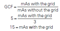
When adding a 12:1 ratio grid, mAs must be increased by a factor of 5 (in this case to 15 mAs).
Likewise, if a radiographer chooses not to use a grid during a procedure but knows the appropriate mAs only for when a grid is used, the mAs must be decreased by the GCF. This calculation requires division by the GCF for the particular grid ratio.
MATHEMATICAL APPLICATION
Removing a Grid
If a radiographer produced a knee radiograph using an 8:1 ratio grid and 10 mAs and on the next exposure wanted to use nongrid exposure, what mAs should be used to produce the same exposure to the IR?
Grid exposure = 10 mAs
GCF (for 8:1 grid) = 4 (from Table 7-2)
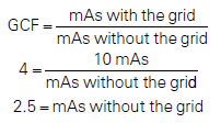
When removing an 8:1 ratio grid, mAs must be decreased by a factor of 4 (in this case to 2.5 mAs).
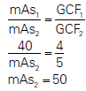
The GCF is also useful when changing between grids with different grid ratios. When changing from one grid ratio to another, the following formula should be used to adjust the mAs:
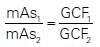
MATHEMATICAL APPLICATION
Decreasing the Grid Ratio
If a radiographer used 40 mAs with a 12:1 ratio grid, what mAs should be used with a 6:1 ratio grid to produce the same exposure to the IR?
Exposure 1: 40 mAs, 12:1 grid, GCF = 5
Exposure 2: _____ mAs, 6:1 grid, GCF = 3
Decreasing the grid ratio requires less mAs.
MATHEMATICAL APPLICATION
Increasing the Grid Ratio
If a radiographer performed a routine portable pelvic examination using 40 mAs with an 8:1 ratio grid, what mAs should be used if a 12:1 ratio grid is substituted?
Exposure 1: 40 mAs, 8:1 grid, GCF = 4
Exposure 2: _____ mAs, 12:1 grid, GCF = 5
Increasing the grid ratio requires additional mAs.
The increase in mAs required to maintain the exposure to the IR results in an increase in patient dose. This increase is significant, as the GCF numbers indicate. It is important to remember that patient dose is increased by the following factors:
- • Using a grid compared with not using a grid
- • Using a higher-ratio grid
Grid Cutoff
In addition to the disadvantage of increased patient dose associated with grid use, another disadvantage is the possibility of grid cutoff. Grid cutoff refers to a decrease in the number of transmitted photons that reach the IR because of some misalignment of the grid. The primary radiographic effect of grid cutoff is a further reduction in the number of photons reaching the IR. Grid cutoff may require the radiographer to repeat the radiographic image, increasing patient dose yet again. Grid ratio has a significant impact on grid cutoff, with higher grid ratios resulting in more potential cutoff.
Types of Grid Cutoff Errors
Grid cutoff can occur because of four types of errors in grid use. To reduce or eliminate grid cutoff, the radiographer must have a thorough understanding of the importance of proper grid alignment in relation to the IR and x-ray tube.
Upside-Down Focused.
Upside-down focused grid cutoff occurs when a focused grid is placed upsidedown on the IR, resulting in the grid lines going opposite the angle of divergence of the x-ray beam resulting in a significant loss of exposure along the edges of the image (Fig. 7-22). Photons easily pass through the center of the grid because the lead lines are perpendicular to the IR surface. Lead lines that are more peripheral to the center have steeper angles and absorb the transmitted photons. Upside-down focused grid error is easily avoided because every focused grid should have a label indicating the tube side. This side of the grid should always face the tube, away from the IR.
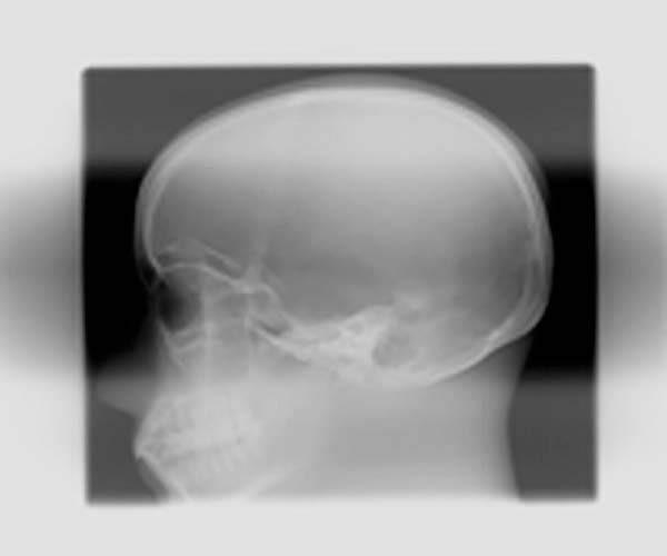
FIG. 7-22 Radiographic image produced with an upside-down focused grid.
Off-Level.
Off-level grid cutoff results when the x-ray beam is angled across the lead strips. It is the most common type of cutoff and can occur from either the tube or the grid being angled (Fig. 7-23). Off-level grid cutoff can often occur with mobile radiographic studies or horizontal beam examinations and is visualized as a loss of exposure across the entire IR. This type of grid cutoff is the only type that occurs with both focused and parallel grids.
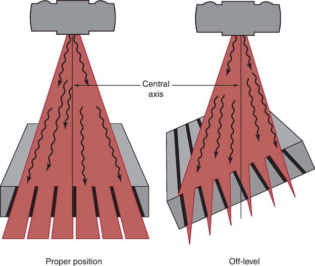
FIG. 7-23 An off-level grid can cause grid cutoff.
Off-Center.
Also called lateral decentering, off-center grid cutoff occurs when the central ray of the x-ray beam is not aligned from side to side with the center of a focused grid. Because of the arrangement of the lead lines of the focused grid, the divergence of the primary beam does not match the angle of these lead strips when not centered (Fig. 7-24). Off-center grid cutoff may cause an overall loss of exposure across the entire IR.
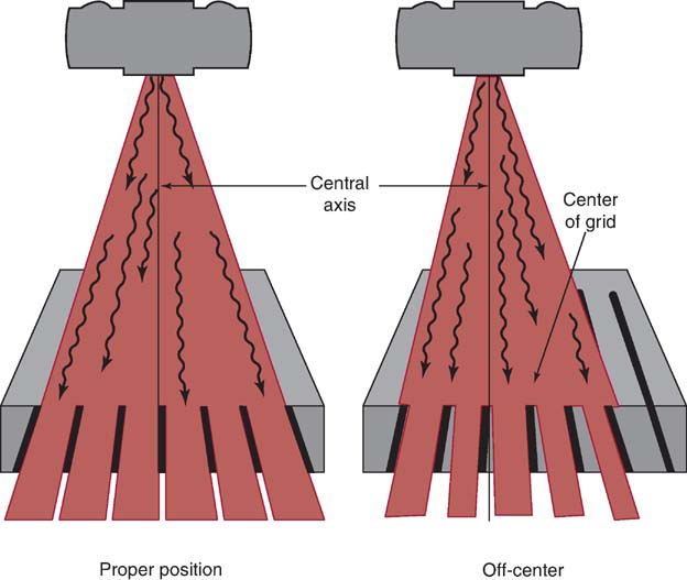
FIG. 7-24 Centering to one side of a focused grid can cause off-center grid cutoff.
Off-Focus.
Off-focus grid cutoff occurs when using an SID outside the recommended focal range. Grid cutoff occurs if the SID is less than or greater than the focal range and results in a loss of exposure at the periphery of the IR.
Grid alignment errors may be difficult to identify because the computer will adjust for exposure errors to the IR. However, adjusting the brightness during computer processing may not overcome a grid alignment error and still produce a poor-quality image (Fig. 7-25). When using a grid, the radiographer should pay close attention to the alignment of the grid to the x-ray tube and IR.
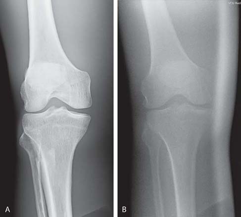
FIG. 7-25 Grid cutoff. A, Image created with proper alignment of computed radiography and no grid cutoff. B, Image created with off-level grid cutoff. The overall brightness was maintained, but the image quality is poor. (From Johnston JN, Fauber TL: Essentials of Radiographic Physics and Imaging, ed 3, St. Louis, 2020, Elsevier.)
Table 7-3 summarizes important relationships regarding the use of radiographic grids.
Moiré Effect
The moiré effect or zebra pattern is an artifact that can occur when a stationary grid is used during computed radiography (CR) imaging (Fig. 7-26). If the grid frequency is similar to the laser scanning frequency or scans parallel to the grid strips during CR image processing, a zebra pattern can result on the digital image. The use of a higher grid frequency or a moving grid with CR digital imaging eliminates this type of grid error. In addition, if a grid cassette is placed in a Bucky, imaging the double grids creates a zebra pattern on the radiograph.
FIG. 7-26 Moiré effect. Radiographic image demonstrating the zebra pattern as a result of the moiré effect. (Courtesy of Andrew Woodward.)
Grid Usage
The radiographer needs to consider several factors when deciding the type of grid, if any, to be used for an examination. Although quite efficient at preventing scatter radiation from reaching the IR, grids are not appropriate for all examinations. When appropriate, selection of a grid involves consideration of contrast improvement, patient dose, and the likelihood of grid cutoff. Radiographers typically choose between parallel and focused grids, high- and low-ratio grids, grids with different focal ranges, and whether to use a grid at all.
As indicated earlier, the choice of whether to use a grid is based on the kVp necessary for the examination and the thickness of the anatomic part being examined. Parts 10 cm (4 inches) or larger, together with kVp values higher than 60, produce enough scatter to necessitate the use of a grid. The next question is which grid to use. There is no single best grid for all situations. A 16:1 focused grid provides excellent contrast improvement, but the patient's dose is high, and the radiographer must ensure that the grid and x-ray tube are perfectly aligned to prevent grid cutoff. The 5:1 parallel grid does a mediocre job of scatter cleanup, especially at kVp values greater than 80. However, the patient dose is significantly lower, and the radiographer need not be concerned with the cutoff caused by being off center, the SID used, or having the grid upside down. Selection between grids with different focal ranges depends on the radiographic examination. Supine abdomen studies should use a grid that includes 40 inches (100 cm) in the focal range; upright chest studies should have grids that include 72 inches (180 cm). In general, most radiographic rooms use a 10:1 or 12:1 focused grid, which provides a compromise between contrast improvement and patient dose. Stationary grids, for mobile examinations, may have a lower ratio, be a parallel type, or both to allow the radiographer greater positioning latitude.
Grids differ from one another in performance, especially in the areas of grid ratio and focal distance. Before using a grid, the radiographer must determine the grid ratio so that the appropriate exposure factors can be selected. Also, the radiographer must be aware of the focal range of focused grids so that an appropriate SID is selected.
Box 7-2 lists the attributes of the grid typically used in radiography. Box 7-3 summarizes grid errors and their radiographic effects. Box 7-4 provides information on quality-control checks for grid uniformity and alignment.
Radiation Protection
Limiting the size of the x-ray field to the anatomic area of interest will decrease scatter production and reduce patient exposure. Although the mAs may be increased to compensate for decreasing the size of the x-ray field, the tissues located closest to the lateral edge or outside the collimated x-ray beam will receive the least amount of radiation exposure. Tissues that lie inside the collimated edge of the x-ray beam will receive the greatest amount of radiation exposure. Collimating to the anatomic area of interest is an important radiation protection practice that should be routinely performed.
The use of grids requires an increase in mAs to maintain exposure to the IR. As a result, patient radiation exposure is increased when using grids. The higher the grid ratio, the greater the mAs needed to maintain exposure to the IR, and therefore, patient radiation exposure is increased. Limiting the use of grids or using a grid with a lower grid ratio decreases the radiation exposure to the patient.
AIR GAP TECHNIQUE
Although the radiographer may use the grid most often to prevent scatter from reaching the IR, the grid is not the only available tool. The air gap technique, although limited in its usefulness, provides another method for limiting the scatter reaching the IR. The air gap technique is based on the simple concept that much of the scatter will miss the IR if there is increased distance between the patient and the IR (increased object-to-image-receptor distance [OID]) (Fig. 7-27). The greater the gap, the greater the reduction in scatter reaching the IR. Like when using a grid, contrast is increased, the number of photons reaching the IR is reduced because less scatter reaches the IR, and the mAs must be increased to compensate. There may be slightly less exposure because a grid absorbs some of the transmitted photons (grid cutoff), but the air gap technique does not.
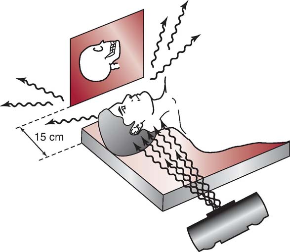
FIG. 7-27 The air gap technique used in magnification radiography of the lateral skull.
The air gap technique is limited in its usefulness because the necessary OID results in decreased spatial resolution. To overcome this increase in unsharpness, an increase in SID is required, which may not always be feasible. The most common use for air gap technique is a trauma lateral cervical spine. Lateral cervical spine positioning creates a natural increase in OID because of the positions of the shoulders.
SCATTER CONTROL AND DIGITAL IMAGING
Computer processing during digital imaging typically produces an image with appropriate brightness. If the amount of x-ray exposure reaching the IR is low, computer processing functions to produce the appropriate brightness, which may result in an image with increased quantum noise. This can occur with all forms of grid cutoff or if the mAs is not increased to compensate for adding a grid or changing to a higher-ratio grid. Excessive noise in a digital image is one of the primary reasons for repeating the image.
If the digital IR receives too much exposure, computer processing produces appropriate brightness; however, image contrast is decreased because of excessive scatter. This may occur when a grid is removed and mAs is not decreased or by not making adjustments in mAs when a change is made to a lower-ratio grid.
Grid errors during digital imaging can easily be masked by computer processing. The radiographer should evaluate the exposure indicator value along with the overall quality of the digital image to determine whether any exposure errors exist.
SHIELDING ACCESSORIES
Efforts to control the amount of scatter radiation produced within the patient and reaching the IR are important considerations during radiography. Restricting the size of the x-ray beam to the anatomic area of interest reduces the radiation exposure to the patient and improves image quality. There are situations in which it is beneficial to use shielding devices to absorb the scatter radiation exiting the patient; placing a lead shield on the x-ray table close to the collimated edge of the area of interest absorbs scatter exiting the patient that could degrade image quality. The lateral lumbar spine projection and the lateral (L5-S1) spot are projections in which a significant amount of scatter exits the patient. Placing a lead shield behind the patient's lower back absorbs the scatter and reduces the amount striking the IR (Fig. 7-28). Accurate placement of the lead shield is important so it does not impact the processing of the digital image. It is important to note that placing a lead shield on the table to limit the scatter radiation reaching the IR does not reduce the exposure to the patient.
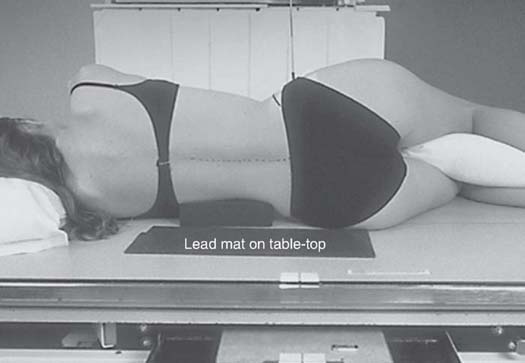
FIG. 7-28 Shielding accessory: lead shield placed to absorb scatter radiation from the patient. (From Bontrager KL, Lampignano JP: Textbook of Radiographic Positioning and Related Anatomy, ed 7, St. Louis, 2010, Mosby.)
Because the patient is the greatest source of scatter radiation, all persons remaining in the radiographic room during an exposure must wear a lead apron. This, together with standing as far from the patient as possible, decreases the amount of occupational exposure to scatter radiation.
It is the radiographer's responsibility to reduce the amount of scatter radiation produced and reaching the IR. Reducing the amount of scatter produced through beam restriction and the amount reaching the IR using a grid, avoiding grid cutoff errors, and making appropriate exposure adjustments as needed help to produce good-quality radiographic images.
CHAPTER SUMMARY
- • Scatter radiation, the result of Compton interactions, is detrimental to radiographic image quality. Excessive scatter results in additional unwanted exposure (fog) and reduced contrast.
- • The effect of scatter radiation can be reduced by limiting the amount produced and by absorbing the scatter before it reaches the IR.
- • The amount of scatter produced increases as the volume of irradiated tissue increases, and the proportion and energy of scatter exiting the patient increase as kVp increases.
- • Beam restriction limits the area exposed to radiation, the patient dose, and the amount of scatter produced in the patient. Aperture diaphragms, cones and cylinders, and collimators are types of beam restrictors.
- • Radiographic grids are devices placed between the patient and the IR to absorb scatter radiation. Consisting of a series of lead strips and radiolucent interspaces, grids allow transmitted radiation to pass through while scatter radiation is absorbed.
- • Grid designs include linear parallel, focused parallel, crossed, short dimension, and long dimension, each with advantages and disadvantages.
- • The use of a grid in a radiographic examination results in fewer photons reaching the IR. The grid conversion (or Bucky) factor is used to calculate the change in exposure (mAs) needed when grids are used.
- • Adding a grid requires an increase in mAs to maintain exposure to the IR, therefore increasing radiation exposure to the patient.
- • Grid alignment errors, producing grid cutoff, include using an upside-down focused grid and errors caused by off-level, off-center, and off-focus equipment alignment.
- • The use and type of a grid depends on the thickness of the part, kVp, patient dose, contrast improvement, and likelihood of grid errors.
- • Grid errors during digital imaging can easily be masked by computer processing.
- • The air gap technique is another method, although seldom used, for reducing the amount of scatter reaching the IR.
- • Placing a lead shield behind the patient's lower back when performing a lateral lumbar spine absorbs the scatter and reduces the amount striking the IR.
- • Because the patient is the greatest source of scatter radiation, all persons remaining in the radiographic room during an exposure must wear a lead apron.
REVIEW QUESTIONS
1. The projected shape of the unrestricted primary beam is __________.
A. square
B. rectangular
C. circular
D. elliptical
2. One purpose of beam-restricting devices is to __________ by changing the size and shape of the primary beam.
A. increase patient dose
B. decrease scatter radiation produced
C. increase exposure to the IR
D. decrease image contrast
3. The most effective type of beam-restricting device is the __________.
A. cone
B. aperture diaphragm
C. cylinder
D. collimator
4. Of the beam-restricting devices listed in question 3, which two are most similar to one another?
A. A and B
B. A and C
C. B and C
D. B and D
5. The purpose of automatic collimation is to ensure that __________.
A. the quantity of scatter production is minimal
B. the field size does not exceed the IR size
C. maximal spatial resolution and contrast are achieved
D. exposure to the IR is maintained
6. When making a significant increase in collimation, __________.
A. mAs should be increased
B. kVp should be increased
C. mAs should be decreased
D. kVp should be decreased
7. Which one of the following increases as collimation increases?
A. Patient exposure
B. Scatter production
C. Fog
D. Contrast
8. Which of the following statements is true for positive beam-limiting devices?
A. They are required on all radiographic installations.
B. They are required on all new radiographic installations.
C. They have never been required on radiographic installations.
D. They were once required on new radiographic installations.
9. The purpose of a grid in radiography is to __________.
A. increase exposure to the IR
B. increase image contrast
C. decrease patient dose
D. increase spatial resolution
10. Grid ratio is defined as the ratio of the __________.
A. height of the lead strips to the distance between them
B. width of the lead strips to their height
C. number of lead strips to their width
D. width of the lead strips to the width of the interspace material
11. Compared with parallel grids, focused grids __________.
A. have a greater grid frequency and lead content
B. can be used with either side facing the tube
C. have a wider range of grid ratios and frequencies
D. allow more transmitted photons to reach the IR
12. With which one of the following grids would a convergent line be formed if imaginary lines from its grid lines were drawn in space above it?
A. Linear focused
B. Crossed focused
C. Linear parallel
D. Crossed parallel
13. If 15 mAs is used to produce a particular level of exposure to the IR without a grid, what value of mAs would be needed to produce that same level of exposure using a 16:1 grid?
A. 45
B. 60
C. 90
D. 105
14. With exposure technique compensation, which of the following would result in the greatest radiation exposure to the patient?
A. 14 × 17 x-ray field size
B. Air gap technique
C. Cylinder beam restrictor
D. 12:1 grid ratio
15. Off-focus grid cutoff occurs by using an SID that is not __________.
A. within the focal range of the grid
B. equal to the focal distance of the grid
C. at the level of the convergent line of the grid
D. at the level of the convergent point of the grid
16. The type of motion most often used for moving grids today is __________.
A. longitudinal
B. reciprocating
C. circular
D. single stroke
17. A grid should be used whenever the anatomic part size exceeds __________.
A. 3 cm
B. 6 cm
C. 10 cm
D. 12 cm
18. The air gap technique uses an increased __________ instead of a grid.
A. kVp
B. mAs
C. SID
D. OID