2: General Anatomy and Radiographic Positioning Terminology

General Anatomy
Body Planes
Sagittal plane
Coronal plane
Horizontal plane

(A) The sagittal plane, coronal plane, horizontal plane, and oblique plane are marked on the human body. A vertical plane running from front to back and divides the body into left and right side median vertical longitudinal plane divides the body into right and left halves. A vertical line runs from side to side and divides the body into anterior and posterior portions. A horizontal plane divides the body into upper and lower parts. (B) The top-down view of a human body shows the sagittal plane through the left shoulder, the coronal plane through the anterior head, and the oblique plane through the right shoulder. (C) The top-down view of a human body shows the Midsagittal plane dividing body equally into right and left halves and the midcoronal plane dividing body equally into anterior and posterior halves.
Oblique plane

(A) An M R I shows the sagittal plane of the knee joint. The femur head has a well-defined outline. (B) An M R I shows the horizontal plane of the knee joint. The intercondylar fossa and posteroinferior articular surfaces of the condyles of the femur are visible. The open joint space is dark. (C) An M R I shows the oblique plane of the knee joint. It is M Shaped. (D) An M R I shows the oblique plane of the knee joint. The soft tissues appear white and the bony elements appear dark and grainy.
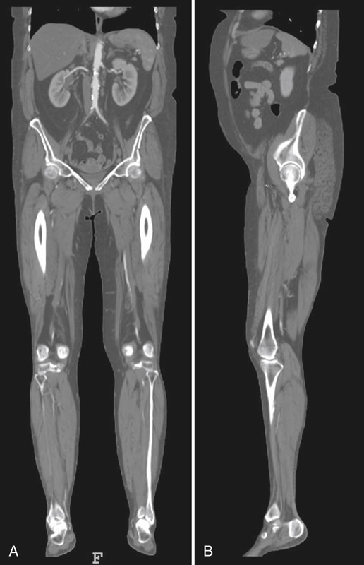
(A) An M R I shows the abdomen and the lower limb including the kidney, acetabulum, and knee. They appear white. (B) An M R I shows the abdomen and the lower limb including the left kidney, left acetabulum, and left knee.
Special Planes
Interiliac plane
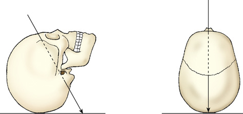
Occlusal plane
Body Cavities
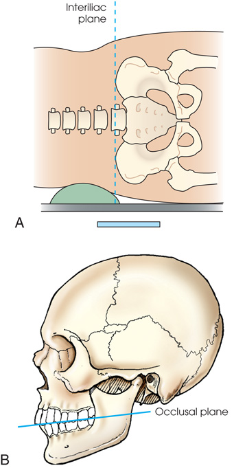
(A) Diagram shows the lateral surface of the body placed on the I R with a support under the body. A horizontal dashed line labeled interillac plane passes through the body. (B) Diagram shows the lateral view of the skull. A dashed line touches the incisal edges of the incisors and tips of the occluding surfaces of the posterior teeth.
Thoracic cavity
Abdominal cavity

An anterior view of the human body shows two cavities. The lungs, heart, abdomen, and pelvis are highlighted. The parts labeled are the thoracic cavity (including pleural cavity and pericardial cavity) and abdominal cavity (abdominopelvic cavity) including abdominal cavity and pelvic cavity.
Divisions of the Abdomen
Quadrants
Regions
Superior
Middle
Inferior


Cutaway model of the human body shows regions of abdomen divided into a 3-by-3 matrix, marked left to right in each region as follows: Upper region: Right hypochondriac, epigastric, and left hypochondriac. Middle region: Right lumbar, umbilical, and left lumbar. Lower region: Right iliac, hypogastric, and left iliac.
Surface Landmarks
| Body structures | External landmarks |
|---|---|
| Cervical area (see Fig. 2.8 ) | |
| C1 | Mastoid tip |
| C2, C3 | Gonion (angle of mandible) |
| C3, C4 | Hyoid bone |
| C5 | Thyroid cartilage |
| C7, T1 | Vertebra prominens |
| Thoracic area | |
| T1 | Approximately 2 inches (5 cm) above level of jugular notch |
| T2, T3 | Level of jugular notch |
| T4, T5 | Level of sternal angle |
| T7 | Level of inferior angles of scapulae |
| T9, T10 | Level of xiphoid process |
| Lumbar area | |
| L2, L3 | Inferior costal margin |
| L4, L5 | Level of superiormost aspect of iliac crests |
| Sacrum and pelvic area | |
| S1, S2 | Level of anterior superior iliac spine (ASIS) |
| Coccyx | Level of pubic symphysis and greater trochanters |

(A) Diagram shows the lateral view of the head. The commonly used landmarks are labeled as follows: T E A (top of ear attachment), gonion, mastoid tip, vertebra prominens, C 1, C 3, C 5, C 7, T 1, T 3, hyoid bone, thyroid cartilage, and jugular notch. (B) Diagram shows the anterior view of the human body or the torso. The commonly used landmarks labeled are marked from top to bottom as follows: C 5 and thyroid cartilage, T 1, T2, T3, and jugular notch, T 4, T 5, and sternal angle, T7 and inferior angle of the scapula, T 9, T 10, and xiphoid process, L 2, L 3, and inferior costal margin, L 4, L 5, and the iliac crest, S 1 and anterior superior iliac spine, and coccyx, pubic symphysis, and greater trochanters.
Body Habitus
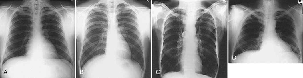
(A) An x-ray shows the lungs in full inspiration. The lungs filled with air appear radiolucent. The heart and the region below the diaphragm appear radiopaque. (B) An x-ray shows the lungs in full expiration. The lungs appear darker than in (A). The diaphragm is depressed. (C) A diagram shows the anterior view of the human body with the lungs highlighted. The diaphragm is positioned lower. An x-ray shows the anterior view of the human body and the lungs appear radiolucent. The diaphragm is positioned lower. The anterior ends of the ribs are less sharply visualized. (D) An x-ray shows the anterior view of the human body and the lungs appear radiolucent. The diaphragm arches posteriorly from the level of about the sixth or seventh costal cartilage to the level of the ninth or tenth thoracic vertebra. The left side of the diaphragm lies at a slightly lower level.

Diagram shows an anterior view of a moderately heavy body titled sthenic 50 percent. Heart: Moderately transverse. Lungs: Moderate length. Diaphragm: Moderately high. Stomach: High, upper left. Colon: Spread evenly; slight dip in the transverse colon. Gallbladder: Centered on the right side, upper abdomen. Abdomen: Moderately long. Thorax: Moderately short, broad, and deep. Pelvis: Relatively small.
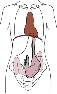
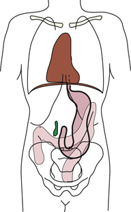
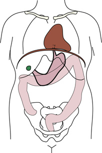
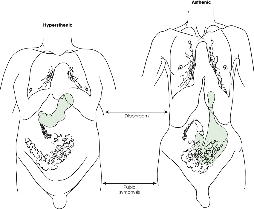
Diagram shows an anterior view of a human body titled hypersthenic on the left and an anterior view of a human body titled asthenic on the right. The abdominal organs are in completely different positions. The diaphragm and the pubic symphysis are the same lengths in both patients. The stomach is shaded in green color. It is high in hypersthenic and low in asthenic.
Osteology
| Area | Bones | Number |
|---|---|---|
| Skull | Cranial | 8 |
| Facial | 14 | |
| Auditory ossicles a | 6 | |
| Neck | Hyoid | 1 |
| Thorax | Sternum | 1 |
| Ribs | 24 | |
| Vertebral column | Cervical | 7 |
| Thoracic | 12 | |
| Lumbar | 5 | |
| Sacrum | 1 | |
| Coccyx | 1 |

(A) shows a skeletal view of the human body. The skull, neck, thorax, and vertebral column are highlighted in blue. (B) shows the skeletal view of the human body. The shoulder girdle, upper limbs, lower limbs, and pelvic girdle are highlighted in blue.
General Bone Features

The general features of the bones are labeled as follows: epiphyseal line, articular cartilage, spongy bone (red marrow), compact bone, endosteum, greater tubercle, trabeculae, medullary cavity (yellow marrow), and periosteum. The trabeculae are filled with red and yellow marrow. The medullary cavity contains trabeculae filled with yellow marrow.

Bone Vessels and Nerves
Bone Development
Intermembranous ossification
Endochondral ossification
Primary ossification

Diagram shows the veins in the long bone. The parts labeled are as follows: epiphyseal line, epiphyseal artery, periosteal arteries, nutrient artery, and nutrient foramen. The epiphyseal artery separately enters the ends of long bones. The periosteal arteries enter at numerous points.
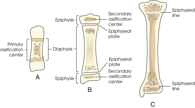
Diagram (A) shows a short central shaft. The parts labeled are the primary ossification center and the diaphysis. Irregular circular patches are between two horizontal lines. Diagram (B) shows a shaft of a bone and the secondary ossification center on the top and the bottom. The parts labeled on the left are epiphysis, diaphysis, and epiphysis. The parts labeled on the right side are the secondary ossification center, epiphyseal plate, epiphyseal plate, and secondary ossification center. A separate bone begins to develop at both ends of each long bone. Diagram (C0 shows a plate of cartilage called the epiphyseal plate develops between the two areas. The parts labeled are the epiphyseal line on top and the epiphyseal line at the bottom. It divides the ends of the epi[hysis into two parts.
Secondary ossification

(A) An x-ray shows the knee joint. The epiphysis and the epiphysial plate are clearly visible. There are open intraarticular joint spaces. (B) An x-ray shows the knee joint. The epiphysial lines are slightly visible. They appear white. Two white arrows point at the lines. (C) An x-ray shows a hand. There are gaps between the proximal ends of phalanges and first metacarpal, distal ends of other metacarpals, and radius.
Classification of Bones
Long bones
Short bones
Flat bones
Irregular bones
Sesamoid bones

Diagram (A) shows a long, narrow, and cylindrical bone. Diagram (B) shows cancellous bones. They are varied in shape. Diagram (C ) shows the flat bone called sternum in the middle and the ribs rise from it. Diagram (D) shows an irregularly shaped bone. Diagram (E) shows a small and oval-shaped bone.
Arthrology

Diagram (A) shows inferior tibiofibular joint. The sheets of fibrous tissue are highlighted and are marked by an arrow. Diagram (B) shows the lateral view of the skull. The sutures are highlighted. An enlarged image shows the sutures of the skull. Diagram (C) shows the roots of teeth in the alveolus. The fibrous periodontal ligaments underlying the tooth are highlighted. The alveolus appears grainy.
Functional Classification
Structural Classification
Fibrous joints
- 1. Syndesmosis: An immovable joint or slightly movable joint united by sheets of fibrous tissue. The inferior tibiofibular joint is an example (Fig. 2.18A).
- 2. Suture: An immovable joint occurring only in the skull. In this joint, the interlocking bones are held tightly together by strong connective tissues. The sutures of the skull are an example (see Fig. 2.18B).
- 3. Gomphosis: An immovable joint occurring only in the roots of the teeth. The roots of the teeth that lie in the alveolar sockets are held in place by fibrous periodontal ligaments (see Fig. 2.18C).
Cartilaginous joints
- 4. Symphysis: A slightly movable joint. The bones in this joint are separated by a pad of fibrocartilage. The ends of the bones contain hyaline cartilage. A symphysis joint is designed for strength and shock absorbency. The joint between the two pubic bones (pubic symphysis) is an example of a symphysis joint (Fig. 2.19A). Another example of a symphysis joint is the joint between each vertebral body. These joints all contain a fibrocartilaginous pad or disk.
- 5. Synchondrosis: An immovable joint. This joint contains a rigid cartilage that unites two bones. An example is the epiphyseal plate found between the epiphysis and diaphysis of a growing long bone (see Fig. 2.19B). Before adulthood, these joints consist of rigid hyaline cartilage that unites two bones. When growth stops, the cartilage ossifies, making this type of joint a temporary joint.

Diagram (A) shows the pubic symphysis highlighted on the pubic bones. An enlarged image below shows the pubic symphysis marked by two blue curves. Diagram (B) shows the epiphyseal plate found between epiphysis and diaphysis of a bone. They are granulated at the ends.
Synovial joints
- 6. Gliding (plane): Uniaxial movement. This is the simplest synovial joint. Joints of this type permit slight movement. They have flattened or slightly curved surfaces, and most glide slightly in only one axis. The intercarpal and intertarsal joints of the wrist and foot are examples of gliding joints (Fig. 2.21A).
- 7. Hinge (ginglymus): Uniaxial movement. A hinge joint permits only flexion and extension. The motion is similar to that of a door. The elbow, knee, and ankle are examples of this type of joint (see Fig. 2.21B).
- 8. Pivot (trochoid): Uniaxial movement. These joints allow only rotation around a single axis. A rounded or pointed surface of one bone articulates within a ring formed partially by the other bone. An example of this joint is the articulation of the atlas and axis of the cervical spine. The atlas rotates around the dens of the axis and allows the head to rotate to either side (see Fig. 2.21C).
- 9. Ellipsoid (condyloid): Biaxial movement, primary. An ellipsoid joint permits movement in two directions at right angles to each other. The radiocarpal joint of the wrist is an example. Flexion and extension occur along with abduction and adduction. Circumduction, a combination of both movements, can also occur (see Fig. 2.21D).
- 10. Saddle (sellar): Biaxial movement. This joint permits movement in two axes, similar to the ellipsoid joint. The joint is so named because the articular surface of one bone is saddle shaped and the articular surface of the other bone is shaped like a rider sitting in a saddle. The two saddle-like structures fit into each other. The carpometacarpal joint between the trapezium and the first metacarpal is the only saddle joint in the body. The face of each bone end has a concave and a convex aspect. The opposing bones are shaped in a manner that allows side-to-side and up-and-down movement (see Fig. 2.21E).
- 11. Ball and socket (spheroid): Multiaxial movement. This joint permits movement in many axes, including flexion and extension, abduction and adduction, circumduction, and rotation. In a ball-and-socket joint, the round head of one bone rests within the cup-shaped depression of the other bone. The hip and the shoulder are examples (see Fig. 2.21F).

A cross-sectional diagram of bone shows labels marked from top to bottom as follows: suprapatellar bursa, articular capsule, infrapatellar bursa, joint cavity (synovial fluid), meniscus (cross-section), articular capsule, synovial membrane, and articular cartilage.

Diagram (A) shows the Intercarpal joints of the wrist. The carpals have yellow granules on them. The cartilages are shaded. Diagram (B) shows the elbow joint. An arrow indicates flexion and extension. Diagram (C ) shows the top view of the atlas and axis of the cervical spine. An arrow points at the ends projecting at the ends. Diagram (D 1, D 2) shows joints of the wrist. An arrow indicates movement in two directions at right angles to each other. Diagram (E) shows the carpometacarpal joint. The face of each bone end has a concave and a convex aspect. An enlarged image of the carpometacarpal joint shows a gap between the two ends. Diagram (F) shows the hip joint. The ball and socket area is highlighted using a dashed line.
Bone Markings and Features
Processes or Projections
- condyle—rounded process at an articular extremity
- coracoid or coronoid—beak-like or crown-like process
- crest—ridge-like process
- epicondyle—projection above a condyle
- facet—small, smooth-surfaced process for articulation with another structure
- hamulus—hook-shaped process
- head—expanded end of a long bone
- horn—horn-like process on a bone
- line—less prominent ridge than a crest; a linear elevation
- malleolus—club-shaped process
- protuberance—projecting part or prominence
- spine—sharp process
- styloid—long, pointed process
- trochanter—either of two large, rounded, and elevated processes (greater or major and lesser or minor) located at junction of neck and shaft of femur
- tubercle—small, rounded, and elevated process
- tuberosity—large, rounded, and elevated process
Depressions
- fissure—cleft or deep groove
- foramen—hole in a bone for transmission of blood vessels and nerves
- fossa—pit, fovea, or hollow space
- groove—shallow linear channel
- meatus—tube-like passageway running within a bone
- notch—indentation into border of a bone
- sinus—recess, groove, cavity, or hollow space, such as (1) recess or groove in bone, as used to designate a channel for venous blood on inner surface of cranium; (2) air cavity in bone or hollow space in other tissue (used to designate a hollow space within a bone, as in paranasal sinuses); or (3) fistula or suppurating channel in soft tissues
- sulcus—furrow, trench, or fissure-like depression
Fractures

Eight diagrams show the classification of the fractures. The first diagram shows compression between the vertebral column. The second diagram shows a leg with an open or compound fracture. A fragment of bone breaking through the skin. The third diagram shows a leg with a simple fracture. A fracture of the bone only, without damage to the surrounding tissue. The fourth diagram shows a leg with a greenstick fracture. There is a crack or break on one side of a long bone. The fifth diagram shows a leg with a transverse fracture. The bone breaks at a 90-degree angle to the long axis. The sixth diagram shows a leg with a spiral or oblique fracture. The break has a curved or sloped pattern. The seventh diagram shows a leg with a comminuted fracture. There is a break in the bone into more than two fragments. The eighth diagram shows a leg with an impacted fracture. The fracture shows bone fragments driven into each other.
Anatomic Relationship Terms
- anterior (ventral) refers to forward or front part of body or forward part of an organ
- posterior (dorsal) refers to back part of body or organ (however, note that the superior surface of the foot is referred to as the dorsal surface)
- caudad refers to parts away from the head of the body
- cephalad refers to parts toward the head of the body
- inferior refers to nearer the feet or situated below
- superior refers to nearer the head or situated above
- central refers to middle area or main part of an organ
- peripheral refers to parts at or near the surface, edge, or outside of another body part
- contralateral refers to part or parts on opposite side of body
- ipsilateral refers to part or parts on same side of body
- lateral refers to parts away from median plane of body or away from the middle of another body part to the right or left
- medial refers to parts toward median plane of body or toward the middle of another body part
- deep refers to parts far from the surface
- superficial refers to parts near skin or surface
- distal refers to parts farthest from point of attachment, point of reference, origin, or beginning; away from center of body
- proximal refers to parts nearer point of attachment, point of reference, origin, or beginning; toward center of body
- external refers to parts outside an organ or on outside of body
- internal refers to parts within or on the inside of an organ
- parietal refers to the wall or lining of a body cavity
- visceral refers to the covering of an organ
- dorsum refers to the top or anterior surface of the foot or to the back or posterior surface of the hand
- palmar refers to the palm of the hand
- plantar refers to the sole of the foot
Radiographic Positioning Terminology
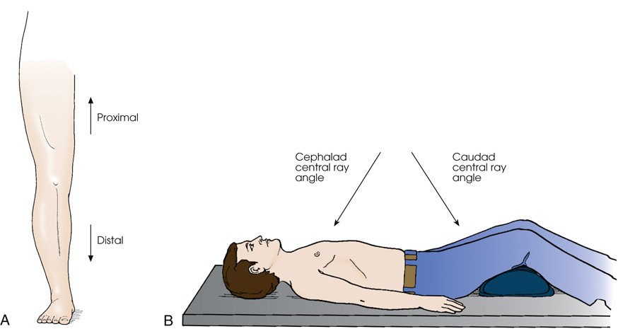
Diagram (A) shows the anterior surface of the leg. An arrow pointing upwards is labeled proximal and an arrow pointing downwards is labeled distal. Diagram (B) shows a patient lying on the radiographic table in a supine position. The legs are elevated by placing a pillow under the knee joints. His arms are placed along the sides of his body. An arrow pointing towards the chest is labeled as cephalad central ray angle and an arrow pointing towards the thighs is labeled as caudad central ray angle.
 Projection
Anteroposterior projection
Posteroanterior projection
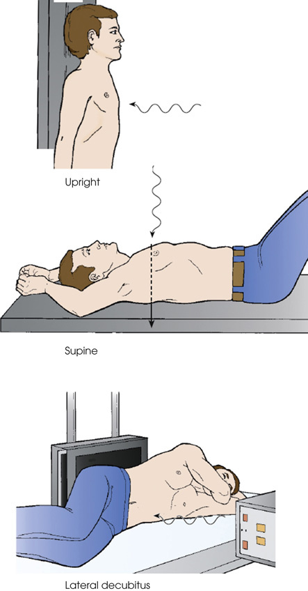
The first diagram shows a patient standing in an upright position against the radiographic table. The perpendicular C R enters the anterior surface. The second diagram shows a patient in a supine position on the radiographic table. The perpendicular C R enters the posterior surface. The third diagram shows a patient's lateral decubitus. A support is placed under the head. The perpendicular C R enters the lateral surface.

The first diagram shows the top view of a patient in a supine position on the radiographic table. The central ray enters the anterior aspect and exits posteriorly. The second diagram shows a patient in a supine position on the radiographic table. The central ray enters the anterior aspect and exits posteriorly.
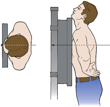
The first diagram shows the top view of a patient standing with his chest against the I R. The central ray enters the anterior aspect and exits posteriorly. The second diagram shows a patient standing with his chest against the I R. The central ray enters the anterior aspect and exits posteriorly.
Axial projection
Tangential projection
The first diagram shows a skull is on a plane with its anterior surface facing up. The central ray is angled 5 to 15 degrees enters the anterior aspect at an angle and exits the posterior aspect. The second diagram shows the top view of a skull on a plane. The central ray enters the anterior aspect at an angle and exits the posterior aspect.

The first diagram shows the dorsal surface of a slight head on the plane. The central ray skims the surface of the skull. The second diagram shows the chin placed on the plane. The central ray is angled 5 to 15 degrees enters the anterior aspect at an angle and exits the posterior aspect.
Lateral projection
Oblique projection
Complex projections

The first diagram shows the top view of a patient standing with his lateral arm against the I R. The central ray (C R) enters the right and exits through the opposite side of the body. The second diagram shows a patient standing with his lateral arm against the I R with both his arms abducted and extended above and resting on his head. The central ray (C R) enters the right and exits through the opposite side of the body.

The humerus and the forearm are placed in contact with the table. The long axis of the elbow joint is parallel with the long axis of the forearm. The central ray enters the lateral aspect of the forearm and exits the medial aspect.

The first diagram shows the top view of a patient standing with his body rotated and the right side of the anterior body surface is against the I R. The central ray enters the posterior aspect of the body and exits the anterior aspect. The second diagram shows a patient lying in a lateral recumbent position. The central ray enters the posterior aspect of the body and exits the anterior aspect.
True projections
In-profile
Position
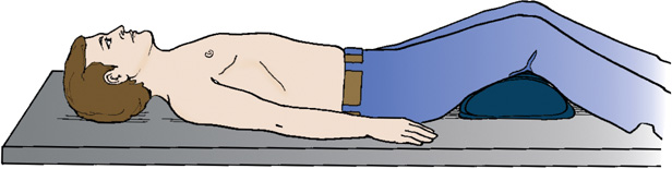
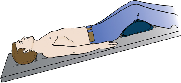
A patient is in a supine position on the radiographic table with their head tilted downward. His arms are placed along the sides of his body. The legs are elevated by placing a pillow under the knee joints.
General body positions
- upright—erect or marked by a vertical position (see Fig. 2.26)
- seated—upright position in which the patient is sitting on a chair or stool
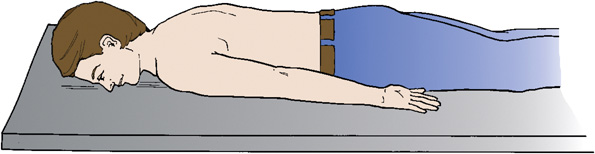
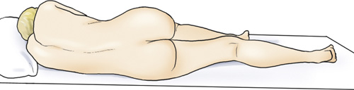
- recumbent—general term referring to lying down in any position, such as dorsal recumbent (Fig. 2.32), ventral recumbent (Fig. 2.33), or lateral recumbent (Fig. 2.34)
- supine—lying on the back (see Fig. 2.32)
- prone—lying face down (see Fig. 2.33)
- Trendelenburg position—supine position with head tilted downward (Fig. 2.35)
- Fowler position—supine position with head higher than the feet (Fig. 2.36)
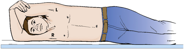
- Sims position—recumbent position with the patient lying on the left anterior side (semiprone) with left leg extended and right knee and thigh partially flexed (Fig. 2.37)
- lithotomy position—supine position with knees and hip flexed and thighs abducted and rotated externally, supported by ankle or knee supports (Fig. 2.38)
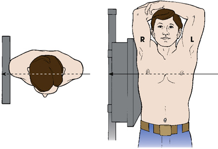
Lateral position

A patient is in a supine position on the radiographic table with a head higher than the feet. His arms are placed along the sides of his body. The legs are elevated by placing a pillow under the knee joints.


The first diagram shows the top view of a patient standing with his lateral arm against the I R. The central ray (C R) enters the right and exits through the opposite side of the body. The second diagram shows a patient standing with his lateral arm against the I R with both his arms abducted and extended above and resting on his head. The central ray (C R) enters the right and exits through the opposite side of the body.
The first diagram shows the top view of a patient standing with his lateral arm against the I R. The central ray (C R) enters the left and exits through the opposite side of the body. The second diagram shows a patient standing with his lateral arm against the I R with both his arms abducted and extended above and resting on his head. The central ray (C R) enters the left and exits through the opposite side of the body.

The first diagram shows the top view of a patient standing with his body rotated and the right side of the anterior body surface is against the I R. The central ray enters the posterior aspect of the body and exits the anterior aspect. The second diagram shows a patient lying in a lateral recumbent position. The central ray enters the posterior aspect of the body and exits the anterior aspect.
The first diagram shows the top view of a patient standing with his body rotated and the left side of the anterior body surface is against the I R. The central ray enters the posterior aspect of the body and exits the anterior aspect. The second diagram shows a patient lying in a lateral recumbent position. The central ray enters the posterior aspect of the body and exits the anterior aspect.
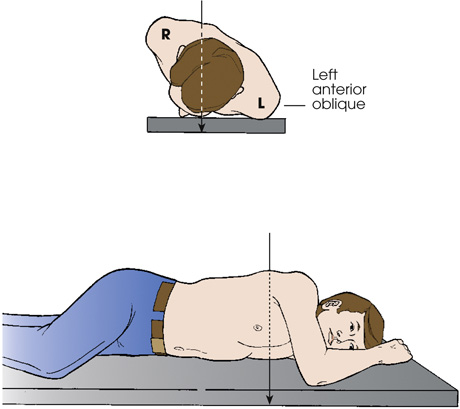
Oblique position
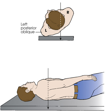
The first diagram shows the top view of a patient standing with his body rotated and the left side of the posterior body surface is against the I R. The central ray enters the posterior aspect of the body and exits the anterior aspect. The second diagram shows a patient lying in a lateral recumbent position. The central ray enters the posterior aspect of the body and exits the anterior aspect.
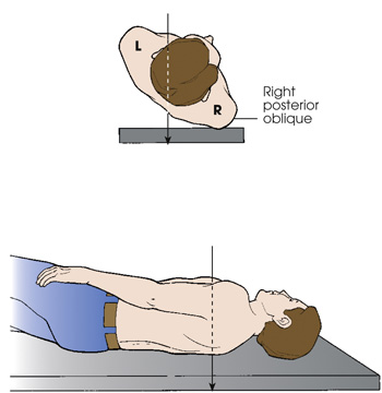
The first diagram shows the top view of a patient standing with his body rotated and the right side of the posterior body surface is against the I R. The central ray enters the posterior aspect of the body and exits the anterior aspect. The second diagram shows a patient lying in a lateral recumbent position. The central ray enters the posterior aspect of the body and exits the anterior aspect.

(A) shows two legs with one leg turned inwards. It is indicated by an arrow pointing towards the other knee. (B) shows two legs with one leg turned outward. It is indicated by an arrow pointing outside.
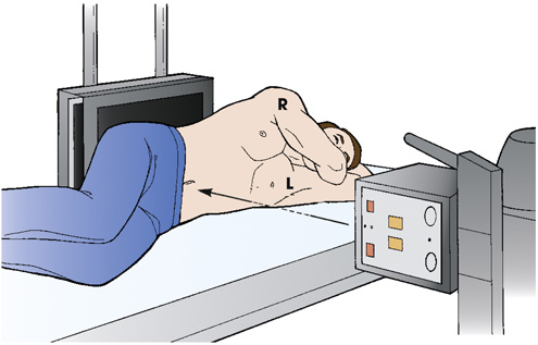

A patient is placed in a dorsal decubitus radiographic position with one side of the body next to the I R. The patient's arms are extended to the vertical position, supporting his head. The central ray is directed horizontally.
Decubitus position
Lordotic position
Note to educators, students, and clinicians
View
Method

The diagram on top shows the top view of a patient with his anterior surface against the table. The side of the body is adjacent to the I R. His arms are placed along the sides of his body. The central ray is directed horizontally. The second diagram shows a patient in a prone position. The side of the body is adjacent to the I R. Both his arms are placed in front of his face. The central ray is directed horizontally.

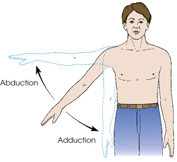
A patient is standing upright with his right arm extended to his side. An arrow pointing up indicates the movement of the arm from the central axis of the body or body part. An arrow pointing down indicates the movement of the arm toward the central axis of the body or body part.

Body Movement Terminology
- abduct or abduction—movement of a part away from the central axis of the body or body part
- adduct or adduction—movement of a part toward the central axis of the body or body part (Fig. 2.50)
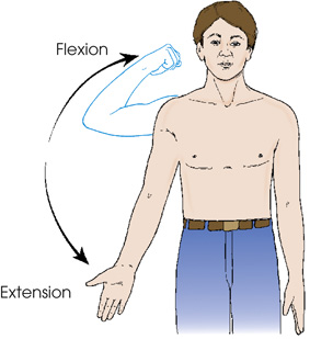
- extension—straightening of a joint; when both elements of the joint are in the anatomic position; normal position of a joint (Fig. 2.51)
- flexion—act of bending a joint; opposite of extension (Fig. 2.52)
- hyperextension—forced or excessive extension of a limb or joints
- hyperflexion—forced overflexion of a limb or joints (see Fig. 2.52)
- evert/eversion—outward turning of the foot at the ankle (Fig. 2.53)
-
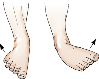
Fig. 2.53 Eversion and inversion of foot at ankle joint. - invert/inversion—inward turning of the foot at the ankle (Fig. 2.53)
- pronate/pronation—rotation of the forearm so that the palm is down
- supinate/supination—rotation of the forearm so that the palm is up (in the anatomic position) (Fig. 2.54)
- rotate/rotation—turning or rotating of the body or a body part around its axis (Fig. 2.55A); rotation of a limb can be medial (toward the midline of the body from the anatomic position [see Fig. 2.55B]) or lateral (away from the midline of the body from the anatomic position [see Fig. 2.55C])
- circumduction—circular movement of a limb (Fig. 2.56)
- tilt—tipping or slanting a body part slightly; tilt is in relation to the long axis of the body (Fig. 2.57)
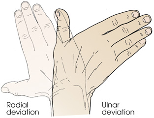
- deviation—turning away from the regular standard or course (Fig. 2.58)
- dorsiflexion—flexion or bending of the foot toward the leg (Fig. 2.59)
- plantar flexion—flexion or bending of the foot downward toward the sole (see Fig. 2.59)

A man standing in an upright position is rotating the forearm so that the palm is down. It is indicated by an arrow pointing inwards. A man standing in an upright position is rotating the forearm so that the palm is up. It is indicated by an arrow pointing outside.
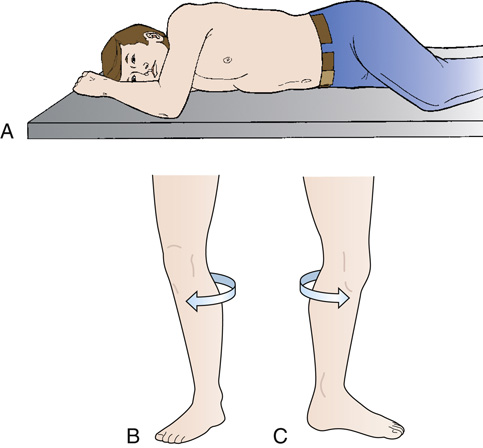
(A) A patient is on the radiographic table by rotating the body around its axis. His knees and elbow are flexed. (B) A leg is rotated toward the midline of the body. It is indicated by an arrow. (C) A leg is rotated away from the midline of the body. It is indicated by an arrow.