10: Bony Thorax

Summary of Projections
| PROJECTIONS, POSITIONS, AND METHODS | |||||
|---|---|---|---|---|---|
| Page | Essential | Anatomy | Projection | Position | Method |
| 520 |

|
Sternum | PA oblique | RAO | |
| 522 | Sternum | PA oblique | Modified prone | MOORE | |
| 524 |
|
Sternum | Lateral | R or L | |
| 526 | Sternoclavicular articulations | PA | |||
| 527 | Sternoclavicular articulations | PA oblique | RAO or LAO | BODY ROTATION | |
| 528 | Sternoclavicular articulations | PA oblique | RAO or LAO | CENTRAL RAY ANGULATION | |
| 531 |
|
Upper anterior ribs | PA | ||
| 533 |
|
Posterior ribs | AP | ||
| 535 |
|
Axillary ribs | AP oblique | RPO or LPO | |
| 537 |
|
Axillary ribs | PA oblique | RAO or LAO | |

Anatomy
Bony Thorax
Sternum

Diagram shows the anterior aspect of the bony thorax. The sternum is directed anteriorly and inferiorly and is centered over the midline of the anterior thorax. The sternum is narrow and flat. The parts labeled in the diagram are as follows. the first, second, third, fourth, fifth, sixth, seventh, eighth, ninth, tenth, eleventh, twelfth ribs, jugular notch, clavicular notch, manubrium, sternal angle, body, xiphoid process, and costal cartilage.

Diagram shows the color-coded anterolateral oblique aspect of the bony thorax. Blue is the true ribs, green is the false ribs, yellow outline with green shading are the floating ribs. The parts labeled are as follows: jugular notch, clavicular notch, manubrium, body, xiphoid process.

Diagram (A) shows the color-coded anterior aspect of the sternum and sternoclavicular joints. The sternum is narrow and flat. Blue is the body, green (outline) is the sternal angle, orange (outline) is the sternoclavicular joints, pink is the manubrium, purple is the xiphoid process, yellow (outline) is the jugular notch. Diagram (B) shows the lateral sternum. It is long and narrow. The parts labeled in the diagram are marked as follows: first, second, third, fourth, fifth, sixth, seventh costal facets, clavicular notch, manubrium, sternal angle, and manubriosternal joint, body, xiphisternal joint, and xiphoid process.
Ribs

Diagram shows 12 pairs of ribs that are numbered consecutively from superiorly to inferiorly. The parts labeled in the diagram are marked as follows: the thoracic vertebrae, lumbar vertebrae, intercostal space, true ribs: 1 to 7, false ribs: 8 to 12, floating ribs, and the costal cartilage. The ribs vary in breadth and length.

Diagram shows the typical rib viewed from the posterior. The parts labeled in the diagram are marked as follows. angle neck head, facet, tubercle, body, costal, groove, and facet. The facets are shaded in blue.
Bony Thorax Articulations


Diagram (A) shows the superior aspect of the rib articulating with the thoracic vertebra and the sternum. The parts labeled in the diagram are marked as follows. body, angle, transverse process, tubercle, head, vertebral body, vertebral end, costal cartilage, sternum, and sternum end. Diagram (B) shows the enlarged image of costovertebral and costotransverse articulations. The parts labeled in the diagram are marked as follows: body, costovertebral joint, costotransverse joint, and spinous process. The body has a triangular part in the middle and it appears grainy. There is a small hollow hole below it.
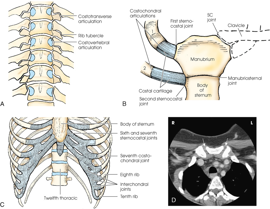
Diagram (A) shows the anterior aspect of the thoracic spine, with costovertebral articulations. The parts labeled in the diagram are marked as follows: costotransverse articulation, costovertebral articulation, and rib tubercle. Diagram. (B) shows the anterior aspect of the manubrium, sternum, and first two ribs, showing articulations. The parts labeled in the diagram are marked as follows: costochondral articulations, costal cartilage, clavicle, first sternocostal joint, second sternocostal joint, s c joint, manubriosternal joint, manubrium, and body of the sternum. The manubrium is shaped like a hexagon and the body of the sternum attaches itself to the manubrium. Diagram (C) shows the lower sternum and ribs, showing intercostal, costochondral, and sternocostal joints. The parts labeled in the diagram are marked as follows. body of sternum, interchondral joints, sixth and seventh sternocostal joints, seventh costochondral joint, eighth rib, twelfth thoracic, and tenth rib. The costal cartilages are shaded in blue. (D) shows a C T image of the upper thorax showing manubrium and angulation of sternoclavicular joints which is marked by two white arrows. The sternoclavicular joints appear white. The open sternoclavicular joint space appears dark.
Respiratory Movement

(A) An x-ray shows the lungs in full inspiration. The posterior ribs are numbered as 1, 3, 6, 7, 10, and 11. The lungs filled with air appear radiolucent. The heart and the region below the diaphragm appear radiopaque. (B) An x-ray shows the lungs in full expiration. The anterior ribs are labeled as 2 A, 4 A, 5 A, 6 A, 7 A, and 8 A. The lungs appear darker than in (A). The diaphragm is depressed.
Diaphragm
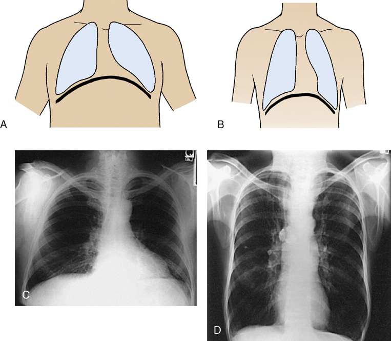
(A) A diagram shows the anterior view of the human body with lungs highlighted. The diaphragm is positioned higher and arches posteriorly. An x-ray view below shows the anterior view of the human body and the lungs appear radiolucent. The diaphragm arches posteriorly from the level of about the sixth or seventh costal cartilage to the level of the ninth or tenth thoracic vertebra. The left side of the diaphragm lies at a slightly lower level (B) A diagram shows the anterior view of the human body with lungs highlighted. The diaphragm is positioned lower. An x-ray view below shows the anterior view of the human body and the lungs appear radiolucent. The diaphragm is positioned lower. The anterior ends of the ribs are less sharply visualized.
Body Position
Trauma Patients
| These techniques were accurate for the equipment used to produce each exposure. However, use caution when applying them in your department because “there is considerable variability in image receptor response owing to varying scatter sensitivity, the use of grids with different grid ratios, collimation, beam filtration, the choice of kilovoltage, source-to-image distance, and IR size.” a | ||||||||
| This chart was created in collaboration with Dennis Bowman, AS, RT(R), Clinical Instructor, Community Hospital of the Monterey Peninsula, Monterey, CA. http://digitalradiographysolutions.com/. | ||||||||
| Bony Thorax | ||||||||
| Part | cm | kVp b | SID c | Collimation | CR d | DR e | ||
|---|---|---|---|---|---|---|---|---|
| mAs | Dose (mGy) f | mAs | Dose (mGy) f | |||||
| Sternum—PA oblique g | 20 | 81 | 30″ | 6″ × 11″ (15 × 28 cm) | 6.3 h | 0.76.5 | 3.2 h | 0.383 |
| Sternum—lateral g | 29 | 81 | 40″ | 5″ × 11″ (13 × 28 cm) | 20h | 2.790 | 10h | 1.395 |
| Sternoclavicular articulations—PA g | 17 | 81 | 40″ | 6″ × 4″ (15 × 10 cm) | 7.1 h | 0.670 | 3.6 h | 0.337 |
| Sternoclavicular articulations—PA oblique g | 18 | 81 | 40″ | 6″ × 4″ (15 × 10 cm) | 10 h | 0.963 | 5 h | 0.479 |
| Upper anterior ribs—PA g | 21 | 81 | 72″ | 9″ × 17″ (23 × 43 cm) | 20 h | 0.625 | 10 h | 0.312 |
| Posterior ribs—AP upper g | 21 | 81 | 72″ | 9″ × 17″ (23 × 43 cm) | 20 h | 0.625 | 10 h | 0.312 |
| Posterior ribs—AP lower g | 21 | 85 | 40″ | 9″ × 12″ (23 × 30 cm) | 25 h | 3.540 | 12.5 h | 1.779 |
| Ribs: axillary—AP oblique g | 23 | 81 | 72″ | 11″ × 17″ (28 × 43 cm) | 36 h | 1.180 | 16 h | 0.522 |
| Ribs: axillary—PA oblique g | 23 | 81 | 72″ | 11″ × 17″ (28 × 43 cm) | 36 h | 1.181 | 16 h | 0.523 |

Radiography
Sternum
Radiation Protection
| Depth of thorax (cm) | Amount of rotation or CR angulation |
|---|---|
| 15 | 22 |
| 16.5 | 21 |
| 18 | 20 |
| 19.5 | 19 |
| 21 | 18 |
| 22.5 | 17 |
| 24 | 16 |
| 25.5 | 15 |
| 27 | 14 |
| 28.5 | 13 |
| 30 | 12 |

(A) A drawing of a chest shows s the central ray is at a 15-degree angle to the sternum. The line drawn next to it is the axial view of the right anterior oblique position and it passes through the sternum. (B) A drawing of a chest shows s the central ray is at a 20-degree angle to the sternum. The line drawn next to it is the axial view of the right anterior oblique position and it passes through the sternum


 PA Oblique Projection
RAO position
SID:
Position of patient
Position of part
- • Adjust the elevation of the left shoulder and hip so that the thorax is rotated just enough to prevent superimposition of the vertebrae and sternum.
- • Estimate the amount of rotation with sufficient accuracy by placing one hand on the patient’s sternum and the other hand on the thoracic vertebrae to act as guides while adjusting the degree of obliquity. The average rotation is approximately 15 to 20 degrees (Fig. 10.15).
- • Align the patient’s body so that the long axis of the sternum is centered to the midline of the grid.
- • Place the top of the IR approximately 1½ inches (3.8 cm) above the jugular notch.
- • Shield gonads.
- • Respiration: When a breathing technique is to be used, instruct the patient to take slow, shallow breaths during the exposure. When a short exposure time is to be used, instruct the patient to suspend breathing at the end of expiration to minimize the visibility of the pulmonary vasculature.

The patient is in a prone position supporting his body with his forearm. A support is placed under the patient's head. The central ray is directed to the elevated side of the posterior thorax perpendicularly. The diagram next to it shows the central ray is at a 15-degree angle to the sternum. The line drawn next to it is the axial view of the right anterior oblique position.
Central ray
Collimation
Structures shown
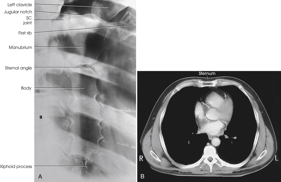
(A) An x-ray shows the entire sternum from the jugular notch to the tip of the xiphoid process. It appears hazy. The parts labeled in the x-ray on the left are marked from top to the bottom as follows: left clavicle, jugular notch, s c joint, first rib, manubrium, sternal angle, body, xiphoid process. (B) The C T shows the sternum in axial plane. The sternum is rectangular and is labeled on the top. The lungs appear dark and the outline of the sternum appears white and prominent.
PA Oblique Projection
Moore Method
Modified prone position
SID:
Position of patient
- • Before positioning the patient, place the IR crosswise in the Bucky tray. Place the x-ray tube at a 30-inch (76-cm) SID, angle it 25 degrees, and direct the CR to the center of the IR. The x-ray tube is positioned over the patient’s right side.
- • Place a marker on the tabletop near the patient’s head to indicate the exact center of the IR.
- • Have the patient stand at the side of the radiographic table directly in front of the Bucky tray.
- • Ask the patient to bend at the waist, and place the sternum in the center of the table directly over the previously positioned IR.
Position of part
- • Place the patient’s arms above the shoulders and the palms down on the table. The arms act as a support for the side of the head (Fig. 10.17).
- • Ensure that the patient is in a true prone position and that the midsternal area is at the center of the radiographic table.
- • Shield gonads.
- • Respiration: A shallow breathing technique produces the best results. Instruct the patient to take slow, shallow breaths during the exposure. A low mA setting and an exposure time of 1 to 3 seconds are recommended. When a low mA setting and long exposure time cannot be employed, instruct the patient to suspend respiration at the end of expiration to minimize the visibility of the pulmonary vasculature.

The patient is standing at the side of the radiographic table and bending his hips over the table with the sternum positioned at the center of the table. The patient's hands are supporting his head. The central ray is directed at a 25-degree angle to the sternum.
Central ray
- • The CR is already angled 25 degrees and centered to the IR. If patient positioning is accurate, the CR enters at the level of T7 and approximately 2 inches (5 cm) to the right of the spine. This angulation places the sternum over the lung to maintain maximum contrast of the sternum.
- • The x-ray tube angulation can be adjusted for extremely large or small patients. Large patients require less angulation and thin patients require more angulation than the standard 25-degree angle.
Collimation
Structures shown
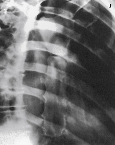
Lateral Projection
Right or left position
SID:
Position of patient
Position of part
Upright
- • Adjust the patient in a true lateral position so that the broad surface of the sternum is perpendicular to the plane of the IR (Fig. 10.19).
- • Rotate the shoulders posteriorly, and have the patient lock the hands behind the back.
- • Being careful to keep the MSP of the body vertical, and place the patient close enough to the grid that the shoulder can be rested firmly against it.
- • Large breasts on female patients should be drawn to the sides and held in position with a wide bandage so that their shadows do not obscure the lower portion of the sternum.
Recumbent
- • Extend the patient’s arms over the head to prevent them from overlapping the sternum (Fig. 10.20).
- • Rest the patient’s head on the arms or on a pillow.
- • Place a support under the lower thoracic region to position the long axis of the sternum horizontally.
- • Shield gonads.
- • Respiration: Suspend deep inspiration. This provides sharper contrast between the posterior surface of the sternum and the adjacent structures.
Central ray
Collimation
Structures shown

The patient is standing in an upright position, lateral to the vertical grid. His hands are held behind his back. The central ray is perpendicular to the vertical grid and directed to the lateral border of the mid sternum.

(A) The patient is lying in a right lateral recumbent position with his arms extended over his head. The central ray is directed to the lateral border of the midsternum. (A)The patient is lying in a supine position. The patient's arms are extended over his head. The central ray is directed to the lateral border of the midsternum.
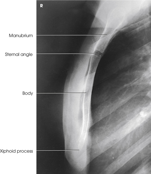
An x-ray shows the lateral sternum. The parts labeled in the x-ray on the left are marked from top to the bottom as follows: the manubrium, sternal angle, body, xiphoid process. The xiphoid process has a white outline and is long and narrow. The sternal angle appears dark.
Sternoclavicular Articulations
PA Projection
Position of patient
Position of part
- • Center the IR at the level of the spinous process of the third thoracic vertebra, which lies posterior to the jugular notch.
- • Place the patient’s arms along the sides of the body with the palms facing upward.
- • Adjust the shoulders to lie in the same transverse plane.
- • For a bilateral examination, rest the patient’s head on the chin and adjust it so that the MSP is vertical.
- • For a unilateral projection, ask the patient to turn the head to face the affected side and rest the cheek on the table (Fig. 10.22). Turning the head rotates the spine slightly away from the side being examined and provides better visualization of the lateral portion of the manubrium.
- • Shield gonads.
- • Respiration: Suspend at the end of expiration.
Central ray
Collimation
Structures shown


An x-ray shows both sternoclavicular joints and the medial ends of the clavicles. The sternum appears radiopaque. There are oval patches with white outlines on the upper portion of the sternum. Two black arrows indicate the bilateral sternoclavicular joints. The clavicle is labeled.

PA Oblique Projection
Body Rotation Method
RAO or LAO position
Image receptor + grid:
Position of patient
Position of part
- • Keeping the affected side adjacent to the IR, position the patient at enough of an oblique angle to project the vertebrae well behind the sternoclavicular joint closest to the IR. The angle is usually approximately 10 to 15 degrees.
- • Adjust the patient’s position to center the joint to the midline of the grid.
- • Adjust the shoulders to lie in the same transverse plane (Fig. 10.25A and B).
- • Shield gonads.
- • Respiration: Suspend at the end of expiration.
Central ray
- • Perpendicular to the sternoclavicular joint closest to the IR. The CR enters at the level of T2-3 (approximately 3 inches [7.6 cm] distal to the vertebral prominens) and 1 to 2 inches (2.5 to 5 cm) lateral from the MSP. If the CR enters the right side, the left sternoclavicular joint is shown, and vice versa (see Fig. 10.25B).
- • Center the IR to the CR.
Collimation
Structures shown

(A) The patient is lying on the radiographic table in the prone position with his arms along the sides of his body. The patient is positioned at an oblique angle of about 10 to 15 degrees. The central ray is directed perpendicular to the sternoclavicular joint. (B) shows the central ray is at a 15-degree angle to the spine. The line is drawn in the axial view of the right anterior oblique position. (c) The x-ray view of the oblique sternoclavicular joint has an arrow pointing at the point.
PA Oblique Projection
CR Angulation Method
Position of patient
Position of part
- • Extend the patient’s arms along the sides of the body with the palms of the hands facing upward.
- • Adjust the shoulders to lie in the same transverse plane.
- • Ask the patient to rest the head on the chin or to rotate the chin toward the side of the joint being radiographed (Fig. 10.26).
Central ray
- • From the side opposite the side being examined, direct to the midpoint of the IR at an angle of 15 degrees toward the MSP. A small angle is satisfactory in examinations of sternoclavicular articulations because only slight anteroposterior overlapping of the vertebrae and these joints occurs.
- • The CR should enter at the level of T2-3 (approximately 3 inches [7.6 cm] distal to the vertebral prominens) and 1 to 2 inches (2.5 to 5 cm) lateral to the MSP. If the CR enters the left side, the right side is shown, and vice versa.
Collimation
Structures shown

(A) The patient is lying on the radiographic table in the prone position with his arms along the sides of his body. The central ray is directed at a 15-degree angle at the M S P. (B) shows the line drawing of the axial view of the sternum that illustrates the central ray is at a 15-degree angle to the spine and sternum.


Ribs
Respiration
SID
Upper Anterior Ribs
PA Projection
Position of patient
- • Position the patient either upright or recumbent, facing the IR.
- • Because the diaphragm descends to its lowest level in the upright position, use the standing or seated-upright position for projections of the upper ribs when the patient’s condition permits (Fig. 10.29). The upright position is also valuable for showing fluid levels in the chest.
Position of part
- • Center the MSP of the patient’s body to the midline of the grid for bilateral ribs.
- • For unilateral ribs, center the affected side on a longitudinal plane drawn midway between the MSP and the lateral surface of the body to the midline of the grid.
- • Adjust the IR position to project approximately 1½ inches (3.8 cm) above the upper border of the shoulders. Less may be required for hypersthenic patients and for those with very muscular shoulders.
- • Rest the patient’s hands against the hips with the palms turned outward to rotate the scapulae away from the rib cage.
- • Adjust the shoulders to lie in the same transverse plane.
- • If the patient is prone, rest the head on the chin and adjust the MSP to be vertical (Fig. 10.30).
- • For hypersthenic patients with wide rib cages, it may be necessary to move the patient laterally to include the entire lateral surface of the affected rib area on the radiograph.
- • Shield gonads.
- • Respiration: Suspend at full inspiration to depress the diaphragm as much as possible.

The patient is standing in an upright position, facing the vertical grid. The patient's hands are resting on his hips with his palm turned outward. The central ray is perpendicular to the center of the I R at the level of T 7.

The patient is lying on the radiographic table in the prone position with his arms along the sides of his body. The central ray is directed perpendicular to the third thoracic vertebrae. The central ray is directed at the seventh thoracic vertebrae perpendicularly.
Central ray
- • Perpendicular to the center of IR. If the IR is positioned correctly, the CR is at the level of T7.
- • A useful option for showing the seventh, eighth, and ninth ribs is to angle the x-ray tube approximately 10 to 15 degrees caudad. This angulation aids in projecting the diaphragm below the affected ribs.
Collimation
Structures shown
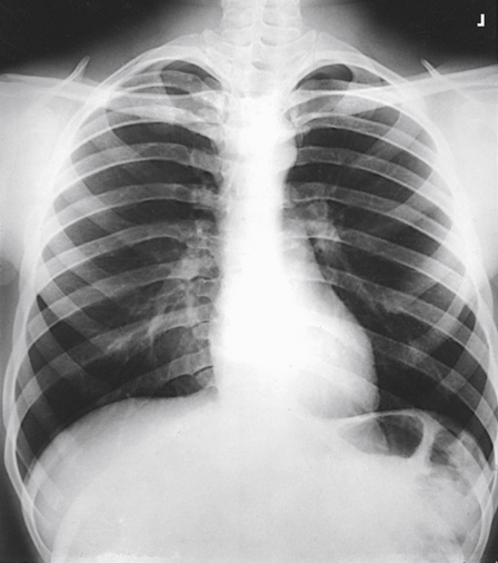

An x-ray shows the anterior ribs above the diaphragm. The left side is labeled posterior rib numbers and the right side is labeled anterior rib numbers. A radiopaque area is aligned towards the right side of the radiograph towards the bottom.
Posterior Ribs
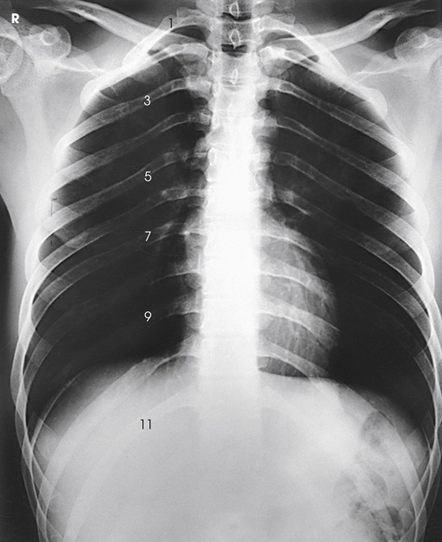
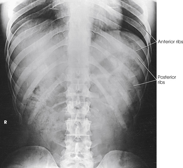
AP Projection
Position of patient
- • Have the patient face the x-ray tube in either an upright or a recumbent position.
- • When the patient’s condition permits, use the upright position to image ribs above the diaphragm and the supine position to image ribs below the diaphragm to permit gravity to assist in moving the patient’s diaphragm.
Position of part
Ribs above diaphragm
- • Place the IR lengthwise 1½ inches (3.8 cm) above the upper border of the relaxed shoulders. Less may be needed for patients with very muscular shoulders.
- • Rest the patient’s hands, palms outward, against the hips. This position moves the scapula off the ribs. Alternatively, extend the arms to the vertical position with the hands under the head (Fig. 10.33).
- • Adjust the patient’s shoulders to lie in the same transverse plane, and rotate them forward to draw the scapulae away from the rib cage.
- • Shield gonads.
- • Respiration: Suspend at full inspiration to depress the diaphragm.
Ribs below diaphragm
- • Place the IR crosswise in the Bucky tray, centered to a point halfway between the xiphoid process and the lower rib margin. The lower edge of the IR will be near the level of the iliac crests. This positioning ensures inclusion of the lower ribs because of the divergent x-rays.
- • Adjust the patient’s shoulders to lie in the same transverse plane.
- • Place the patient’s arms in a comfortable position (Fig. 10.34).
- • Shield gonads.
- • Respiration: Suspend at full expiration to elevate the diaphragm.

The patient is lying in a supine position. The patient's arms are extended to the vertical position, supporting his head. The central ray is directed to 3.8 centimeters above the upper border of the shoulders.

The patient is lying in a supine position. The patient's arms are extended to the sides, supporting his head. The central ray is directed to the point between the xiphoid process and the lower rib margin.
Central ray
Collimation
Structures shown
Axillary Ribs
AP Oblique Projection
RPO or LPO position
Position of patient
Position of part
- • Position the patient’s body for a 45-degree AP oblique projection using the RPO or LPO position. Place the affected side closest to the IR.
- • Center the affected side on a longitudinal plane drawn midway between the MSP and the lateral surface of the body.
- • Position this plane to the midline of the grid.
- • If the patient is in the recumbent position, support the elevated hip.
- • Abduct the arm of the affected side, and elevate it to carry the scapula away from the rib cage.
- • Rest the patient’s hand on the head if the upright position is used (Fig. 10.37), or place the hand under or above the head if the recumbent position is used (Fig. 10.38).
- • Abduct the opposite limb with the hand on the hip.
- • Center the IR with the top 1½ inches (3.8 cm) above the upper border of the relaxed shoulder to image ribs above the diaphragm or to a point halfway between the xiphoid process and the lower rib margin to image ribs below the diaphragm.
- • Shield gonads.
- • Respiration: Suspend at the end of full inspiration for ribs above the diaphragm and at the end of deep expiration for ribs below the diaphragm.

The patient is standing in an upright position facing the I R at a 45-degree angle to the vertical grid. The arm of the affected side is abducted and extended above and resting on his head. The central ray is directed to 3.8 centimeters above the upper border of the shoulders.

The patient is lying in a supine position with his hips elevated to a 45-degree angle. The arm of the affected side is abducted and extended above, supporting his head. The central ray is directed to 3.8 centimeters above the upper border of the shoulders.
Central ray
Collimation
Structures shown
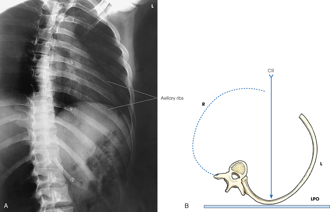
(A) An x-ray shows the axillary portion of the ribs free of superimposition with the thoracic spine. The ribs labeled are 3, 6, 9, 12. The axillary ribs are labeled. (B) A diagram shows the L P O position with hips elevated. The central ray is directed perpendicular to the center of the I R.
PA Oblique Projection
RAO or LAO position
Position of patient
Position of part
- • Position the body for a 45-degree PA oblique projection using the RAO or LAO position. Place the affected side away from the IR (Fig. 10.40).
- • If the recumbent position is used, have the patient rest on the forearm and flexed knee of the elevated side (Fig. 10.41).
- • Align the body so that a longitudinal plane drawn midway between the midline and the lateral surface of the body side up is centered to the midline of the grid.
- • Center IR with the top 1½ inches (3.8 cm) above the upper border of the shoulder to image ribs above the diaphragm or to a point halfway between the xiphoid process and the lower rib margin to image ribs below the diaphragm.
- • Shield gonads.
- • Respiration: Suspend at the end of full expiration for ribs below the diaphragm and at the end of full inspiration for ribs above the diaphragm.

The patient is standing in an upright position facing the vertical grid at a 45-degree angle to the vertical grid. The affected side is positioned away from the I R. The central ray is directed to 3.8 centimeters above the upper border of the shoulders.

The patient is lying in a supine position with his hips elevated to a 45-degree angle positioning the affected side away from the I R. The central ray is directed to 3.8 centimeters above the upper border of the shoulders.
Central ray
Collimation
Structures shown

An x-ray shows the axillary portion of the ribs free of superimposition with the thoracic spine. The axillary ribs labeled appear light over the radiolucent area. The eighth through twelfth ribs are visible below the diaphragm for lower ribs. The sternum appears radiopaque.