14: Myelography and Other Central Nervous System Imaging

Unlabeled image
Rebecca H. Keith

Anatomy

For descriptive purposes, the central nervous system (CNS) is divided into two parts: (1) the brain, a which occupies the cranial cavity, and (2) the spinal cord, which is suspended within the vertebral canal.
image
Fig. 14.1  Lateral surface and midsection of brain.

Two illustrations of the lateral view of the brain. The first one depicts the cerebellum above the brainstem and the lateral sulcus on the surface of the brain. The second one depicts the cerebrum, cerebellum and the corpus collosum below the cerebrum. The brainstem emerges from the center and consists of pons, medula oblongata, and midbrain. The spinal cord extends from the brainstem.

Brain

The cerebrum is the largest part of the brain and is referred to as the forebrain. Its surface is convoluted by shallow sulci and deeper grooves (fissures) that divide it into lobes and lobules. There are four lobes of the cerebrum, each named for its location within the cranium: the frontal lobe, parietal lobe, occipital lobe, and temporal lobe. The stemlike portion that connects the cerebrum to the pons and cerebellum is termed the midbrain. The cerebellum, pons, and medulla oblongata make up the hindbrain.
A deep cleft, called the longitudinal sulcus (interhemispheric fissure), separates the cerebrum into right and left hemispheres, which are closely connected by bands of nerve fibers, or commissures. The largest commissure between the cerebral hemispheres is the corpus callosum. The corpus callosum is a midline structure inferior to the longitudinal sulcus. Each cerebral hemisphere contains a fluid-filled cavity called a lateral ventricle. At the diencephalon, or second portion of the brain, the pair of oval-shaped gray matter masses of the thalamus surround the third ventricle. Inferior to the diencephalon is the pituitary gland, the master endocrine gland of the body. The pituitary gland resides in the hypophyseal fossa of the sella turcica.
The cerebellum, the largest part of the hindbrain, is separated from the cerebrum by a deep transverse cleft. The hemispheres of the cerebellum are connected by a median constricted area called the vermis. The surface of the cerebellum contains numerous transverse sulci that account for its cauliflower-like appearance. The tissues between the curved sulci are called folia. The pons, which forms the upper part of the hindbrain, is the commissure, or bridge, between the cerebrum, cerebellum, and medulla oblongata. The medulla oblongata, which extends between the pons and spinal cord, forms the lower portion of the hindbrain. All the fiber tracts between the brain and spinal cord pass through the medulla.

Spinal Cord

The spinal cord is a slender, elongated structure consisting of an inner gray, cellular substance, which has a butterfly shape on the transverse section and an outer white, fibrous substance (Figs. 14.2 and 14.3). The cord extends from the brain, where it is connected to the medulla oblongata at the level of the foramen magnum, to the approximate level of the space between the first and second lumbar vertebrae. The spinal cord ends in a pointed extremity called the conus medullaris (see Fig. 14.3). The filum terminale is a delicate fibrous strand that extends from the terminal tip and attaches the cord to the upper coccygeal segment.
In an adult, the spinal cord is 18 to 20 inches (46 to 50 cm) long and is connected to 31 pairs of spinal nerves. Each pair of spinal nerves arises from two roots (dorsal and ventral) at the sides of the spinal cord. The nerves are transmitted through the intervertebral and sacral foramina. Spinal nerves below the termination of the spinal cord extend inferiorly through the vertebral canal. These nerves resemble a horse’s tail and are referred to as the cauda equina. The spinal cord and nerves work together to transmit and receive sensory, motor, and reflex messages to and from the brain.

Meninges

The brain and spinal cord are enclosed in three continuous protective membranes called meninges. The inner sheath, called the pia mater (Latin, meaning “tender mother”), is highly vascular and closely adherent to the underlying brain and cord structure.
The delicate central sheath is called the arachnoid. This membrane is separated from the pia mater by a comparatively wide space called the subarachnoid space, which is widened in certain areas. These areas of increased width are called subarachnoid cisterns. The widest area is the cisterna magna (cisterna cerebellomedullaris). This triangular cavity is situated in the lower posterior fossa between the base of the cerebellum and the dorsal surface of the medulla oblongata. The subarachnoid space is continuous with the ventricular system of the brain and communicates with it through the foramina of the fourth ventricle. The ventricles of the brain and the subarachnoid space contain cerebrospinal fluid (CSF). CSF is the tissue fluid of the brain and spinal cord; it surrounds and cushions the structures of the CNS.
image
Fig. 14.2  Transverse section of spinal cord.

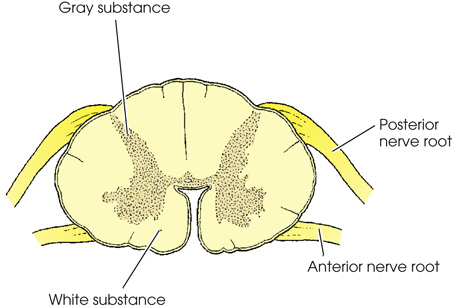
A transverse view of the spinal cord has a H shaped gray substance and a surrounding white substance. The posterior nerve root and the anterior nerve root rise from the top and the bottom portion respectively.

The outermost sheath, called the dura mater (Latin, meaning “tough mother”), forms the strong fibrous covering of the brain and spinal cord. The dura is separated from the arachnoid by the subdural space and from the vertebral periosteum by the epidural space. These spaces do not communicate with the ventricular system. The dura mater is composed of two layers throughout its cranial portion. The outer layer lines the cranial bones, serving as periosteum to their inner surface. The inner layer protects the brain and supports the blood vessels. The inner layer also has four partitions that provide support and protection for the various parts of the brain. One of these partitions, the falx cerebri, runs through the longitudinal fissure and provides support for the cerebral hemispheres. The tentorium cerebelli is a tent-shaped fold of dura that separates the cerebrum and cerebellum. Changes in the normal positions of these structures often indicate pathology. The dura mater extends below the spinal cord (to the level of the second sacral segment) to enclose the spinal nerves, which are prolonged inferiorly from the cord to their respective exits. The lower portion of the dura mater is called the dural sac. The dural sac encloses the cauda equina.
image
Fig. 14.3  Sagittal section showing spinal cord.

The lateral view of the head and upper body. The Pons lies at the base of the brain, followed by the medula oblongata. The spinal cord starts at the base of the brain and ends at the lumbar region. The Conus medullaris and Dural sac for cauda equina are at the end of the spinal cord.

Ventricular System

The ventricular system of the brain consists of four irregular, fluid-containing cavities that communicate with one another through connecting channels (Figs. 14.4 through 14.6). The two upper cavities are an identical pair and are called the right and left lateral ventricles. They are situated, one on each side of the midsagittal plane, in the inferior medial part of the corresponding hemisphere of the cerebrum.
Each lateral ventricle consists of a central portion called the body of the cavity. The body is prolonged anteriorly, posteriorly, and inferiorly into horn-like portions that give the ventricle an approximate U shape. The prolonged portions are known as the anterior, posterior, or occipital, and inferior or temporal horns. Each lateral ventricle is connected to the third ventricle by a channel called the interventricular foramen, or foramen of Monro, through which it communicates directly with the third ventricle and indirectly with the opposite lateral ventricle.
image
Fig. 14.4  Lateral aspect of cerebral ventricles in relation to surface of brain.

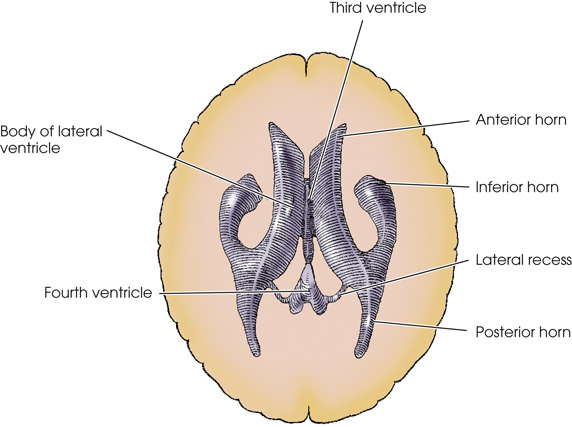
The lateral view of the cerebral ventricles of the brain. The lateral ventricle is a horn like U shaped structure at the center. It is extends into the anterior horn on the left and the posterior horn on the right. It is connected to a quadrilateral-shaped third ventricle through the intraventricular foramen. It is connected to the diamond-shaped fourth ventricle on the hind brain through the cerebral aqueduct.

The third ventricle is a slit-like cavity with a quadrilateral shape. It is situated in the midsagittal plane just inferior to the level of the bodies of the lateral ventricles. This cavity extends anteroinferiorly from the pineal gland, which produces a recess in its posterior wall, to the optic chiasm, which produces a recess in its anteroinferior wall.
The interventricular foramina, one from each lateral ventricle, open into the anterosuperior portion of the third ventricle. The cavity is continuous posteroinferiorly with the fourth ventricle by a passage known as the cerebral aqueduct, or aqueduct of sylvius.
The superior view of the cerebral ventricles. The body of the lateral ventricle with the anterior, posterior, and inferior horns, third ventricle, fourth ventricle, and lateral recess are visible.
Fig. 14.6  Superior aspect of cerebral ventricles in relation to surface of brain.
M R I scan image of the spine. The cerebro-spinal fluid in the sub arachnoid space, thecal sac, conus medullaris, cauda equina, and filum terminale are labeled.
Fig. 14.7  Mid-sagittal T2-weighted magnetic resonance image demonstrating spinal cord within the vertebral canal, along with thecal sac and cerebrospinal fluid (CSF) flowing in the subarachnoid space.

Radiography

Plain Radiographic Examination

Neuroradiologic assessment should begin with noninvasive imaging procedures. Radiographs of the cerebral and visceral cranium and the vertebral column may be obtained to show bony anatomy. In traumatized patients (see Chapters 9 and 12), radiographs are obtained to detect bone injury, subluxation, or dislocation of the vertebral column and to determine the extent and stability of the bone injury. Computed tomography (CT) is often employed first in a trauma setting due to its speed and ability to demonstrate both soft tissue and bony anatomy (see Chapter 25).
For a traumatized patient with possible CNS involvement, a cross-table lateral cervical spine radiograph may be obtained to rule out fracture or misalignment of the cervical spine. Approximately two-thirds of significant pathologic conditions affecting the spine can be detected on this initial image. Care must be taken to image the entire cervical spine adequately, including the C7–T1 articulation. Employing the Swimmer’s technique (see Chapter 9) may be necessary to show this anatomic region radiographically.
After the cross-table lateral radiograph has been checked and cleared by a physician or advanced practitioner, the following cervical spine projections should be obtained: AP, bilateral AP oblique (trauma technique may be necessary), and AP to show the dens. A vertebral arch, or pillar image, of the cervical spine may provide additional information about the posterior portions of the cervical vertebrae (see Chapter 9). An upright lateral cervical spine radiograph may also be requested to show alignment of the vertebrae better and to assess the normal lordotic curvature of the spine.
Radiographs of the spine should always be obtained before myelography. Routine images of the vertebral column are helpful in assessing narrowed disk spaces because of degeneration of the disk, osteoarthritis, postoperative changes in the spine, and other pathologies of the vertebral column. Because the contrast agents used in myelography may obscure some anomalies, noncontrast spinal images complement the myelographic examination and often provide additional information.
Routine skull images may be obtained when the possibility of a skull fracture exists. In trauma patients, a cross-table lateral or upright lateral skull radiograph may be obtained to show air-fluid levels in the sphenoid sinus. In many instances, these air-fluid levels may be the initial indication of a basilar skull fracture. A noncontrast head CT is indicated in head trauma patients who experience a loss of consciousness or other neurologic symptoms. In addition, skull images are helpful in diagnosing reactive bone formation and general alterations in the skull resulting from various pathologic conditions, including Paget disease, fibrous dysplasia, hemangiomas, and changes in the sella turcica.

Myelography

Myelography (Greek, myelos, “marrow; the spinal cord”) is the general term applied to radiologic examination of the CNS structures situated within the vertebral canal. This examination is performed by introducing a nonionic, water-soluble contrast medium into the subarachnoid space by spinal puncture, most commonly at the L2–L3 or L3–L4 interspace or into the thecal sac via a lateral C1–C2 puncture. Injections into the subarachnoid space are termed intrathecal injections. A tilting table facilitates the positioning of the contrast medium to the desired region.
A scan image of the spinal cord with a small portion illuminated by contrast medium.
Fig. 14.8  Myelogram using nonionic water-soluble contrast medium (iopamidol) on a postsurgical patient.
Most myelograms are performed on an outpatient basis, with patients recovering for approximately 4 to 8 hours after the procedure before being released to return home. In many parts of the United States, magnetic resonance imaging (MRI) (see Chapter 26) has largely replaced myelography. Myelography continues to be the preferred examination method for assessing disk disease in patients with contraindications to MRI, such as pacemakers or metallic posterior spinal fusion rods.
Myelography is employed to show extrinsic spinal cord compression caused by a herniated disk, bone fragments, or tumors and spinal cord swelling resulting from traumatic injury. These encroachments appear radiographically as a deformity in the subarachnoid space or an obstruction of the passage of the column of contrast medium within the subarachnoid space. Myelography is also useful for identifying a narrowing of the subarachnoid space by evaluating the dynamic flow patterns of the CSF. Myelography may also demonstrate CSF leak and be used for surgical planning.
Contrast Media
Technologists who perform myelography should be educated regarding the use of contrast media. Intrathecal administration of ionic contrast media may cause severe and fatal neurotoxic reactions. Because vials of ionic and nonionic agents may look similar, radiology departments are encouraged to store contrast media for myelography separately from other agents. Proper medication guidelines must be followed when intrathecal agents are administered. Contrast vials should be checked three times and checked with the physician or advanced practitioner performing the examination. They should be kept until the procedure has been completed. All appropriate documentation must be completed.
Preparation of the Examining Room
The spinal puncture and injection of contrast medium are performed in the radiology department utilizing sterile technique. The Centers for Disease Control and Prevention (CDC) requires that surgical masks be worn when a catheter is being placed or material injected into the spinal canal or subdural space. Subcutaneous and intramuscular local anesthetic is administered. Under fluoroscopic observation, placement of the 20- to 25-gauge spinal needle in the subarachnoid space is verified and the nonionic iodinated contrast medium injected. The sterile tray and the nonsterile items required for this initial procedure should be ready for convenient placement.
A patient lies face down on a table below a fluroscopy tower. Two medical practitioners assist her.
Fig. 14.9  Patient set up with shoulder supports and fluoroscopy tower in locked position.
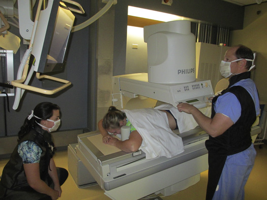
Examination Procedure
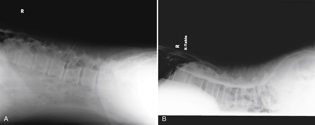
Premedication of the patient for myelography may be necessary, depending on the patient. The patient should be well hydrated, however, because a nonionic water-soluble contrast medium is used. To reduce apprehension and prevent alarm at unexpected maneuvers during the procedure, the radiographer should explain the details of myelography to the patient before the examination begins. The patient should be informed that the angulation of the examining table will change repeatedly and acutely. The patient should also be told why their head must be maintained in a fully extended position when the table is tilted to the Trendelenburg position. The radiographer must ensure that the patient will be safe when the table is acutely angled and that everything possible is being done to avoid causing unnecessary discomfort. Most facilities require an informed consent form to be completed and signed by the patient and physician. The risks and benefits of the procedure and of possible alternatives should be addressed.
Scout images, including a cross-table lateral lumbar spine prone (Fig. 14.10), are often requested. Some physicians/practitioners prefer to have the patient placed on the table in the prone position for the spinal puncture. Alternately, some physicians/practitioners have the patient adjusted in the lateral position, with the spine flexed to widen the interspinous spaces for easier introduction of the needle.
A patient lies face down on a table below a fluroscopy tower. An image receptor is placed adjacent to her abdomen.
Fig. 14.10  Lateral scout projection of cross-table lumbar spine myelogram.
The physician/practitioner may withdraw CSF for laboratory analysis. Approximately 9 to 12 mL of nonionic contrast medium is slowly injected under intermittent imaging. After completing the injection, the physician removes the spinal needle. Travel of the column of contrast medium is observed and controlled fluoroscopically. Angulation of the table allows gravity to direct the contrast medium to the area of interest. Spot images are taken throughout the procedure. The radiographer obtains images at the level of any blockage or distortion in the outline of the contrast column. Conventional radiographic studies, with the central ray directed vertically or horizontally, may be performed as requested by the radiologist. The conus projection is used to show the conus medullaris. For this projection, the patient is placed in the AP position with the central ray centered to T12–L1. A 10 × 12-inch (24 × 30-cm) exposure field is used. Cross-table lateral radiographs are obtained using a crosswise image receptor with a grid and close collimation (Figs. 14.11 through 14.15).
Two myelograms of the lumbar spine. In A, a needle tip is inserted in the subarachnoid space. In B, the same image is repeated with contrast.
Fig. 14.11  (A) Lumbar myelogram. Cross-table lateral showing needle tip in the subarachnoid space. (B) Lumbar myelogram. Cross-table lateral showing contrast enhancement.
The position of the patient’s head must be guarded as the contrast medium column nears the cervical area to prevent the medium from passing into the cerebral ventricles. Acute extension of the head compresses the cisterna magna and prevents further ascent of the contrast medium. Because the cisterna magna is situated posteriorly, neither forward nor lateral flexion of the head will compress the cisternal cavity. The technologist should employ proper radiation protection practices, including wearing lead gloves if support of the patient’s head during fluoroscopy is deemed necessary.
After completion of the procedure, the patient must be monitored in an appropriate recovery area. Most physicians/practitioners recommend that the patient’s head and shoulders be elevated 30 to 45 degrees during recovery. Bed rest for several hours is recommended, and fluids are encouraged. The puncture site must be examined before the patient is released from the recovery area. If the myelogram is performed on an outpatient basis, the patient should be instructed regarding limitations, including no driving, and warning signs of adverse reactions.
A myelogram of the spinal cord with an arrow pointing to the subarachnoid space.
Fig. 14.15  Myelogram. Lateral projection showing narrowing of the subarachnoid space (arrow).
Lumbar Puncture

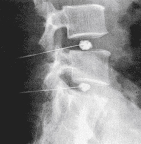
Vertebral Augmentation

Vertebral augmentation includes several percutaneous techniques aimed at stabilizing weakened vertebral bodies. Vertebroplasty, kyphoplasty, and mesh-container-plasty are interventional radiology procedures used to treat spinal osteoporotic compression fractures and other pathologies, such as bone weakened by neoplasia of the vertebral bodies that do not respond to conservative treatment. Vertebral compression fractures (VCFs) are common, especially in older patients with a history of osteoporosis. Estimates indicate that osteoporosis causes more than 700,000 vertebral fractures per year in the United States. About half of these fractures occur silently without any pain. Some fractures are extremely painful, however, and severely limit the patient’s quality of life. The morbidity of symptomatic VCFs is significant, causing chronic pain, sleep loss, depression, and a loss of the ability to perform activities of daily living. Vertebral augmentation is used in cases of severe pain that does not improve over many weeks of conservative treatment.
Percutaneous vertebroplasty is defined as the injection of a radiopaque bone cement (e.g., polymethyl methacrylate) into a painful compression fracture under fluoroscopic guidance. This procedure is typically performed in the special procedures suite or the operating room with the patient sedated but awake. A specialized trocar needle is advanced into the fractured vertebral body under fluoroscopy (Fig. 14.17). Intraosseous venography using nonionic contrast media is performed to confirm needle placement. When the physician is satisfied with the needle placement, the cement is injected (Fig. 14.18). The cement stabilizes fracture fragments and leads to reduction in pain. Postprocedural imaging includes AP and lateral projections of the spine to confirm cement position (Fig. 14.19). A CT scan may also be performed.
A patient lies on the stomach on a table. The head and stomach are rested on a cushion.
Fig. 14.16  Prone position for lumbar puncture and myelography. Fluoroscopic image demonstrating spinal needle localization.
A myelogram of a magnified part of the spine. A thin needle is lodged inside.
Fig. 14.17  Lateral projection of a compressed vertebral body with bone needle in place.
A myelogram of a magnified part of the spine. Bone cement is injected using a needle.
Fig. 14.18  Bone cement injected during vertebroplasty under image guidance.
Percutaneous kyphoplasty differs from vertebroplasty in that a balloon catheter is used to expand the compressed vertebral body to near its original height before injection of the bone cement. Inflation of the balloon creates a pocket for the placement of the cement. Kyphoplasty can help restore the spine to a more normal curvature and reduce hunchback deformities.
Percutaneous mesh-container-plasty utilizes a bone expansion brace to cut the bone tissues. After the brace is withdrawn, a mesh container is advanced into the cavity and the cement is injected into the container. This technique restores vertebral body height and strengthens bony trabeculae.
Two myelograms A and B of the spine show the bone cement in L 1 as a darkened region.
Fig. 14.19  (A) and (B) AP and lateral projections show bone cement in L1.
The success of these procedures is measured by significant reduction of pain, reduced disability, and improved quality of life reported by the patient. With proper patient selection and technique, success rates of 80% to 90% have been reported. Vertebral augmentation procedures have risks of serious complications, however. Major complications occur in less than 1% of patients treated for compression fractures. The most common complication is leakage of the cement before it hardens. Pulmonary embolism and death, although rare, have been reported. Patients should be encouraged to discuss risks, benefits, and alternatives with their physicians. Technologists who perform these procedures need to be properly educated and ensure that informed consent has been documented.

Other Neuroradiographic Procedures

Provocative Diskography
Diskography is a procedure performed under fluoroscopic guidance to determine whether the disc is the source of a patient’s chronic back pain. The examination is performed with a small quantity of water-soluble nonionic iodinated medium injected into the center of the disk. Diskography is used in the investigation of internal disk lesions, such as rupture of the nucleus pulposus, which cannot be shown by other imaging procedures (Fig. 14.20). Patients are given only a local anesthetic so that they remain fully conscious and able to inform the physician about pain when the needles are inserted and the injection is made. Attempts are made to replicate the patient’s chronic pain during the injection. CT is usually performed after diskography to look for clefts or tears. Spinal fusion is often recommended based on a positive provocation of pain. The need for this procedure should be carefully evaluated because there is controversy regarding the sensitivity and specificity of the examination. Some authors have suggested that diskography may increase the chance of later disk disruption. MRI and CT have largely replaced diskography.
Interventional Pain Management
Image-guided interventional pain management is becoming a common treatment for chronic back pain that does not respond to conservative treatment. Pretreatment assessment of the patient’s pain and a thorough history are necessary. Fluoroscopy, CT, and ultrasonography are often used to confirm needle placement. Interventional pain management physicians perform a variety of injections using corticosteroids and local anesthetics to reduce inflammation and improve symptoms. Procedures can be performed at all levels of the spine and include facet injections, nerve root blocks, and epidural steroid injections. Various needle types can be used, but needles with a stylet are most common to prevent tissue from being trapped in the lumen. Size and tip configuration are determined by the physician. Patients are placed in the prone position (Fig. 14.21). A pillow placed under the pelvis may help with patient comfort. C-arm fluoroscopy is commonly used to determine needle placement. The C-arm may have to be rotated several times to identify the needle path. Images are taken to document the procedure, needle position, and contrast distribution. PA and lateral projections are needed to confirm needle depth. The tip of the needle and an identifiable bony landmark must be included in the images. The precise nature of the injections is thought to improve patient outcomes compared with blind injections. The success of the treatment is based on the patient’s self-report of pain reduction.
A myelogram of the cervical spine. The normal nucleus pulposus of round contour type is visible.
Fig. 14.20  Lumbar diskogram showing normal nucleus pulposus of round contour type.
A patient lies on the stomach on a table with a C-arm setup. The head is rested on a cushion. Two medical practitioners assist him.
Fig. 14.21  Patient set up with C-arm for pain management injection.

Definition of Terms