Part TwonImaging Principles
Contributor Andrew Woodward, MA, RT(R)(CT)(QM)
This period of technologic transition necessitates that students have an understanding of all image acquisition technologies, because they will find themselves working in imaging departments that acquire images by using only digital technology, only film-screen technology, or a combination of both.
This part provides an introduction to radiographic technique and image quality for both film-screen imaging and digital imaging. The study of radiographic technique and image quality includes factors that determine the accuracy with which structures that are being imaged are reproduced in the image. Each of these factors has a specific effect on the final image, and the technologist must strive to maximize these factors to produce the best image possible at the lowest achievable dose.
This part also describes methods of digital image acquisition, discusses the application of digital imaging, and provides an introduction to the important principles of radiation safety.
Technical considerations for both analog and digital imaging technology are discussed in the following sections.
Exposure Factors
For each radiographic image obtained, the radiographer must select exposure factors on the control panel of the imaging equipment. The exposure factors required for each examination are determined by numerous variables, including the density/atomic number and thickness of the anatomic part, any pathology present, and image acquisition technology. Fig. 1.125 is an example of a more current radiographic control console.
Exposure factors, sometimes referred to as technique factors, include the following:
-
- • Kilovoltage (kVp)—controls the energy (penetrating power) of the x-ray beam. This can also be referred to as kilovoltage peak (kVp)—the maximum electrical potential used to create the x-ray photons within the x-ray tube.
- • Milliamperage (mA)—controls the quantity or number of x-rays produced.
- • Exposure time (ms)—controls the duration of the exposure, usually expressed in milliseconds.
Each of these exposure factors has a specific effect on the signal collected to produce the radiographic image. When performing radiographic procedures, technologists must apply their knowledge of exposure factors and imaging principles to ensure that images obtained are of the highest quality possible while exposing patients to the lowest radiation dose possible.
Image Quality
Spatial Resolution
Spatial resolution is defined as the recorded sharpness of structures on the image. Resolution on a radiographic image is demonstrated by the clarity or sharpness of fine structural lines and borders of tissues or structures on the image. Resolution is also known as detail, recorded detail, image sharpness, or definition. Resolution of images generally is measured and expressed as line pairs per millimeter (lp/mm), in which a line pair is seen as a single line and an interspace of equal width. The higher the line pair measure, the greater is the resolution; it is typically 5 to 6 lp/mm for general imaging. Lack of visible sharpness or resolution is known as blur or unsharpness.
Geometric Factors Affecting Spatial Resolution
Geometric factors that control or influence resolution consist of focal spot size, source–image receptor distance (SID), and object–image receptor distance (OID). The effect of OID is explained and illustrated in Fig. 1.131.
The use of the small focal spot results in less geometric unsharpness (Fig. 1.126). To illustrate, a point source is used commonly as the source of x-rays in the x-ray tube; however, the actual source of x-rays is an area on the anode known as the focal spot. Most x-ray tubes exhibit dual focus; that is, they have two focal spots: large and small. Use of the small focal spot results in less unsharpness of the image, or an image with a decreased penumbra. Penumbra refers to the unsharp edges of objects in the projected image. However, even with the use of the small focal spot, some penumbra is present.
Motion
The greatest deterrent to image sharpness as related to positioning is motion. Two types of motion influence radiographic detail: voluntary and involuntary.


Voluntary motion is that which the patient can control. Motion from breathing or movement of body parts during exposure can be prevented or at least minimized by controlled breathing and patient immobilization. Support blocks, sandbags, or other immobilization devices can be used to reduce motion effectively. These devices are most effective for examination of upper or lower limbs, as will be demonstrated throughout this text.
Involuntary motion cannot be controlled by the patient at will. Therefore, involuntary motion, such as peristaltic action of abdominal organs, tremors, or chills, is more difficult, if not impossible, to control.
If motion unsharpness is apparent on the image, the technologist must determine whether this blurring or unsharpness is due to voluntary or involuntary motion. This determination is important, because these two types of motion can be controlled in various ways.
Difference between voluntary and involuntary motion
Voluntary motion is visualized as generalized blurring of linked structures, such as blurring of the thoracic bony and soft tissue structures as evident in Fig. 1.127. Voluntary motion can be minimized through the use of high mA and short exposure times. Increased patient cooperation is another factor that may contribute to decreased voluntary motion; a thorough explanation of the procedure and clear breathing instructions may prove helpful.
Involuntary motion is identified by localized unsharpness or blurring. This type of motion is less obvious but can be visualized on abdominal images as localized blurring of the edges of the bowel, with other bowel outlines appearing sharp (gas in the bowel appears as dark areas). Study Fig. 1.128 carefully to see this slight blurring in the left upper abdomen, indicated by arrows. The remaining edges of the bowel throughout the abdomen appear sharp. Fig. 1.127, by comparison, demonstrates overall blurring of the heart, ribs, and diaphragm. A clear explanation of the procedure by the technologist may aid in reducing voluntary motion; however, a decrease in exposure time with an associated increase in mA is the best and sometimes the only way to minimize motion unsharpness caused by involuntary motion.
Summary of Spatial Resolution Factors
Use of a small focal spot, an increase in SID, and a decrease in OID result in less geometric unsharpness and increased resolution. Patient motion also affects image quality; short exposure times and increased patient cooperation help to minimize voluntary motion unsharpness. Involuntary motion unsharpness is controlled only by short exposure times.
Distortion
The second image quality factor is distortion, which is defined as the misrepresentation of object size or shape as projected onto radiographic recording media. Two types of distortion have been identified: size distortion (magnification) and shape distortion.
No radiographic image reproduces the exact size of the body part that is being radiographed. This is impossible to do because a degree of magnification or distortion or both always exists as a result of OID and divergence of the x-ray beam. Nevertheless, distortion can be minimized and controlled if some basic principles are used as a guide.
X-Ray Beam Divergence
X-ray beam divergence is a basic but important concept in the study of radiographic positioning. It occurs because x-rays originate from a small source in the x-ray tube (the focal spot) and diverge as they travel to the IR (Fig. 1.129). The field size of the x-ray beam is limited by a collimator that consists of adjustable lead attenuators or shutters. The collimator and shutters absorb the x-rays on the periphery, controlling the size of the x-ray beam.


The center point of the x-ray beam, which is called the central ray (CR), theoretically has no divergence; the least amount of distortion is seen at this point on the image. All other aspects of the x-ray beam strike the IR at some angle, with the angle of divergence increasing to the outermost portions of the x-ray beam. The potential for distortion at these outer margins is increased.
Fig. 1.129 demonstrates three points on a body part (marked A, B, and C) as projected onto the IR. Greater magnification is demonstrated at the periphery (A and B) than at the point of the central ray (C). Because of the effect of the divergent x-ray beam, combined with at least some OID, this type of size distortion is inevitable. It is important for technologists to control closely and minimize distortion as much as possible.
Controlling Factors
Following are four primary controlling factors of distortion:
SID
The first controlling factor for distortion is SID. The effect of SID on size distortion (magnification) is demonstrated in Fig. 1.130. Note that less magnification occurs at a greater SID than at a shorter SID. This is the reason that chest radiographs are obtained at a minimum SID of 72 inches (180 cm) rather than of 40 to 48 inches (100 to 120 cm), which is commonly used for most other examinations. A 72-inch (180-cm) SID results in less magnification of the heart and other structures within the thorax.
Minimum 40-inch (100-cm) SID
It has been a long-standing common practice to use 40 inches (100 cm) as the standard SID for most skeletal radiographic examinations. However, in the interest of improving image resolution by decreasing magnification and distortion, it is becoming more common to increase the standard SID to 44 inches or 48 inches (110 cm or 120 cm). Additionally, it has been shown that increasing the SID from 40 to 48 inches reduces the entrance or skin dose even when the requirement for increased mAs is considered. In this textbook, the suggested SID listed on each skeletal positioning page is a minimum of 40 inches, with 44 inches or 48 inches recommended if the equipment and departmental protocol allow.
OID
The second controlling factor for distortion is OID. The effect of OID on magnification or size distortion is illustrated clearly in Fig. 1.131. The closer the object being radiographed is to the IR, the less are the magnification and shape distortion and the better is the resolution.
Object–Image Receptor Alignment
A third important controlling factor of distortion is object–IR alignment. This refers to the alignment or plane of the object that is being radiographed in relation to the plane of the image receptor. If the object plane is not parallel to the plane of the IR, distortion occurs. The greater the angle of inclination of the object or the IR, the greater the amount of distortion. For example, if a finger being radiographed is not parallel to the IR, the interphalangeal joint spaces will not be open because of the overlapping of bones, as is demonstrated in Fig. 1.132.
Effect of improper object-IR alignment
In Fig. 1.133, the digits (fingers) are supported and aligned parallel to the image receptor, resulting in open interphalangeal joints and undistorted phalanges.


In Fig. 1.134, in which the digits are not parallel to the IR, the interphalangeal joints of the digits are not open, and possible pathology within these joint regions may not be visible. Note the open joints of the digits in Fig. 1.135 compared with Fig. 1.136 (see arrows). Additionally, the phalanges will be either foreshortened or elongated.
These examples demonstrate the important principle of correct object-IR alignment. The plane of the body part that is being imaged must be as near parallel to the plane of the IR as possible to produce an image of minimal distortion.
CR Alignment
The fourth and final controlling factor for distortion is central ray alignment (centering), an important principle in positioning. As was previously stated, only the center of the x-ray beam, the CR, has no divergence because it projects that part of the object at 90°, or perpendicular to the plane of the IR (refer to Fig. 1.129). Therefore, the least possible distortion occurs at the CR. Distortion increases as the angle of divergence increases from the center of the x-ray beam to the outer edges. For this reason, correct centering or correct central ray alignment and placement is important in minimizing image distortion.
Examples of correct CR placement for an AP knee are shown in Figs. 1.137 and 1.138. The CR passes through the knee joint space with minimal distortion, and the joint space should appear open.
Fig. 1.139 demonstrates correct centering for an AP distal femur, in which the CR is correctly directed perpendicular to the IR and centered to the mid distal femur. However, the knee joint is now exposed to divergent rays (as shown by the arrow), and this causes the knee joint to appear closed (Fig. 1.140).
CR angle
For most projections, the CR is aligned perpendicular, or 90°, to the plane of the IR. For certain body parts, however, a specific angle of the CR is required, as is indicated by the positioning descriptions in this text as the CR angle. This means that the CR is angled from the vertical in a cephalic or caudad direction so as to use distortion intentionally without superimposing anatomic structures.
Summary of Factors That May Affect Distortion
Use of the correct SID while minimizing OID, ensuring the object and IR are aligned, and correctly aligning or centering the CR to the part can minimize distortion on a radiographic image (Table 1.6).
Scatter Radiation and Grids
Grids
Because the amount of scatter increases with the thickness of the tissue irradiated, it generally is recommended that a grid should be used for radiography of any body part that is thicker than 10 cm. Depending on the examination, the grid may be portable or may be built into the x-ray equipment. It is positioned between the patient and the IR and absorbs much of the scatter radiation before it hits the IR. Absorption of scatter is a key event that increases image contrast.
Correct Use of Grids
An in-depth discussion of grid construction and characteristics is beyond the scope of this text. However, several rules must be followed to ensure optimal image quality when grids are used. Incorrect use of grids results in loss of optical density across all or part of the radiographic image; this feature is called grid cutoff. Grid cutoff occurs in various degrees and has several causes. Causes of grid cutoff include the following:


TABLE 1.6

Off-center grid
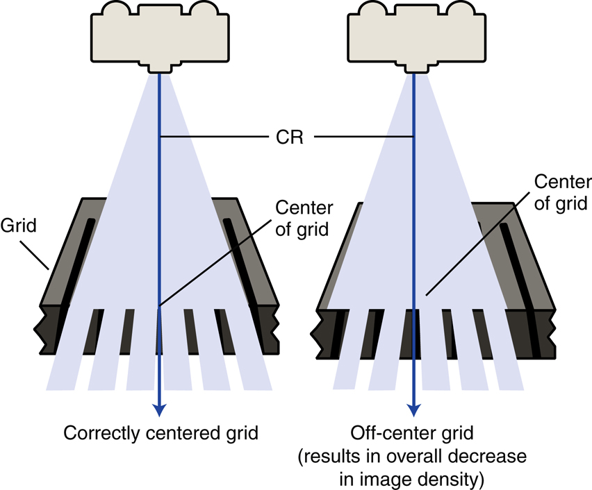
The CR must be centered along the center axis of the grid. If it is not, lateral decentering is said to occur. The more the CR is off center from the centerline of the grid, the greater is the cutoff that results (Fig. 1.141).
In certain clinical situations in which it is difficult to position the area of interest in the center of the grid, the grid may have to be turned so that the lead strips run perpendicular to the length of the patient to allow accurate centering (e.g., horizontal beam lateral lumbar spine).
Exception: decubitus—short dimension (SD)–type linear grids
An exception to the more common lengthwise focused grid with the lead strips and center axis running lengthwise with the grid is the decubitus-type crosswise linear grid. This grid, in which the lead strips and center axis are running crosswise along the shorter dimension of the grid, is useful for horizontal beam decubitus-type projections. For these projections, the grid is placed lengthwise with the patient, but the CR is centered along the crosswise axis of the grid to prevent grid cutoff.
Off-level grid
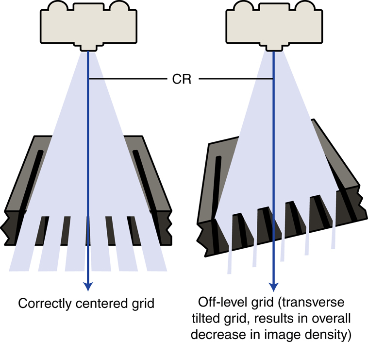
With angling, the CR must be angled along the long axis of the lead strips. Angling across the grid lines results in grid cutoff. Off-level grid cutoff also occurs if the grid is tilted; the CR hits the lead lines at an angle (Fig. 1.142).
Off-focus grid
A focused grid must be used at a specified SID if grid cutoff is to be prevented. Grids typically have a minimum and a maximum usable SID; this is called the focal range. The focal range is determined by the grid frequency (number of grid strips per inch or centimeter) and the grid ratio (height of lead strips compared with the space between them). Portable grids generally have a lower grid frequency and a lower grid ratio than fixed grids or bucky-type grids. A common grid ratio for portable grids is 6:1 or 8:1 compared with 12:1 for bucky grids. This indicates a greater focal range for portable grids, but SID limitations still exist to prevent grid cutoff (Fig. 1.143). Each technologist should know which types of portable grids are available and should know the focal range of each.
Upside-down focused grid
Each grid is labeled to indicate the side that must be positioned to face the x-ray tube. The lead strips are tilted or focused to allow the x-ray beam to pass through unimpeded (if the SID is within the focal range and the grid is correctly placed). If the grid is positioned upside-down, the image will show severe cutoff (Fig. 1.144).

