Chapter 3: Abdomen
Contributions By Kelli Welch Haynes, Ed.D., RT(R), Contributors to Past Editions Dan L. Hobbs, MSRS, RT(R)(CT)(MR), John P. Lampignano, MEd, RT(R)(CT), Kathy M. Martensen, BS, RT(R), and Barry T. Anthony, RT(R)
Radiographic Anatomy
Abdominal Radiography
This chapter covers the anatomy and positioning for images of the abdomen. To examine the abdomen radiographically, one or more projections may be performed. The most common image is an anteroposterior (AP) supine abdomen, also sometimes called a KUB (kidneys, ureters, and bladder) because of the regions visualized. These are taken without the use of contrast media. Radiographs of the abdomen (KUB) are commonly performed prior to fluoroscopic abdominal examinations, which are performed with the use of contrast media to rule out certain pathologies.
Acute Abdominal Series
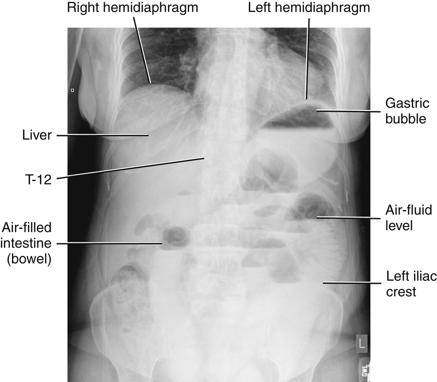
Certain acute or emergency conditions of the abdomen may develop from conditions such as bowel obstruction, perforations involving free intraperitoneal air (air outside the digestive tract), excessive fluid in the abdomen (ascites), or a possible intra-abdominal mass. These acute or emergency conditions require what is commonly referred to as an “acute abdominal series,” wherein several abdominal images are taken in different positions to demonstrate air-fluid levels, free air, or both within the abdominal cavity. Typically, a supine KUB along with an upright AP or decubitus abdomen and a PA or AP chest are performed to complete the series.
Abdominal radiography requires an understanding of anatomy and relationships of the organs and structures within the abdominopelvic cavity.
Abdominal Muscles
Many muscles are associated with the abdominopelvic cavity. The most important in abdominal radiography are the right and left hemi-diaphragms and the right and left psoas (so′-es) major and minor muscles. The right hemi-diaphragm is attached anteriorly to the fifth rib and posteriorly at the level of the tenth rib. The left hemi-diaphragm is located near the first intercostal space. The psoas major muscles are located laterally to the lumbar vertebrae.
The diaphragm is an umbrella-shaped muscle that separates the abdominal cavity from the thoracic cavity. The diaphragm must be perfectly motionless during imaging of the abdomen or the chest. Motion of the patient’s diaphragm can be stopped when appropriate breathing instructions are given to the patient.
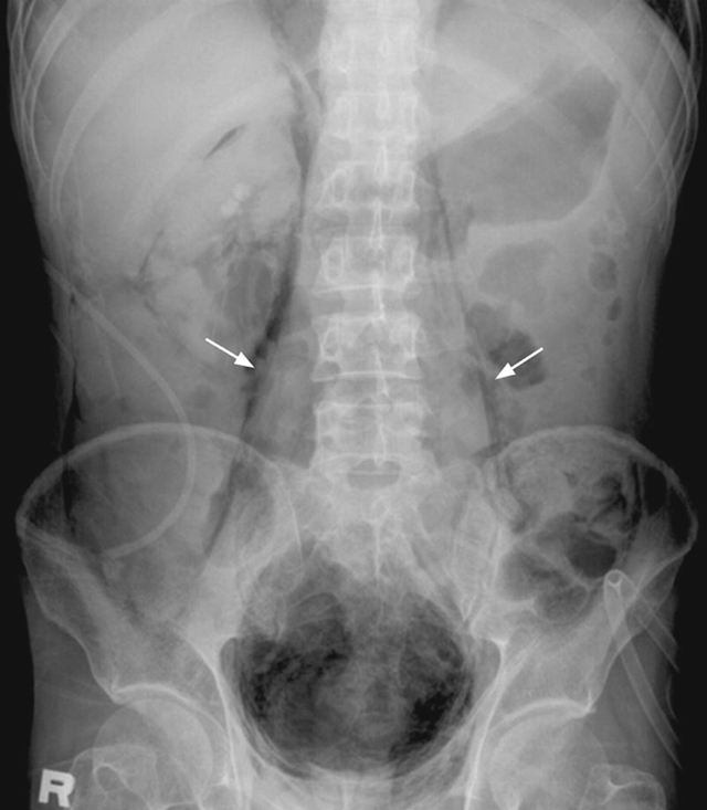
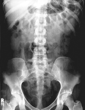
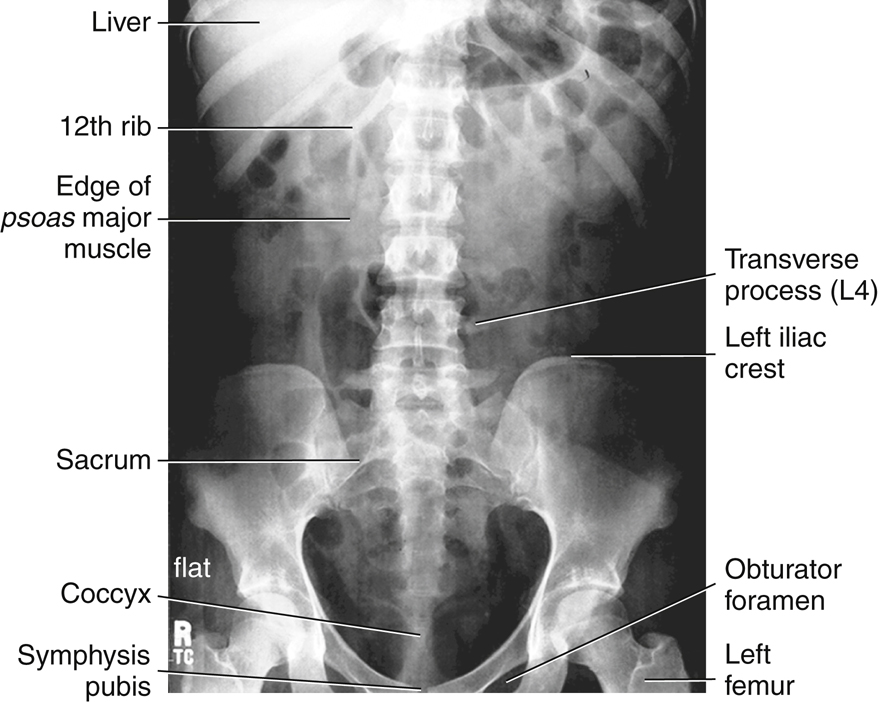
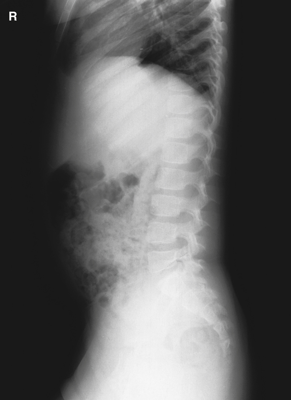
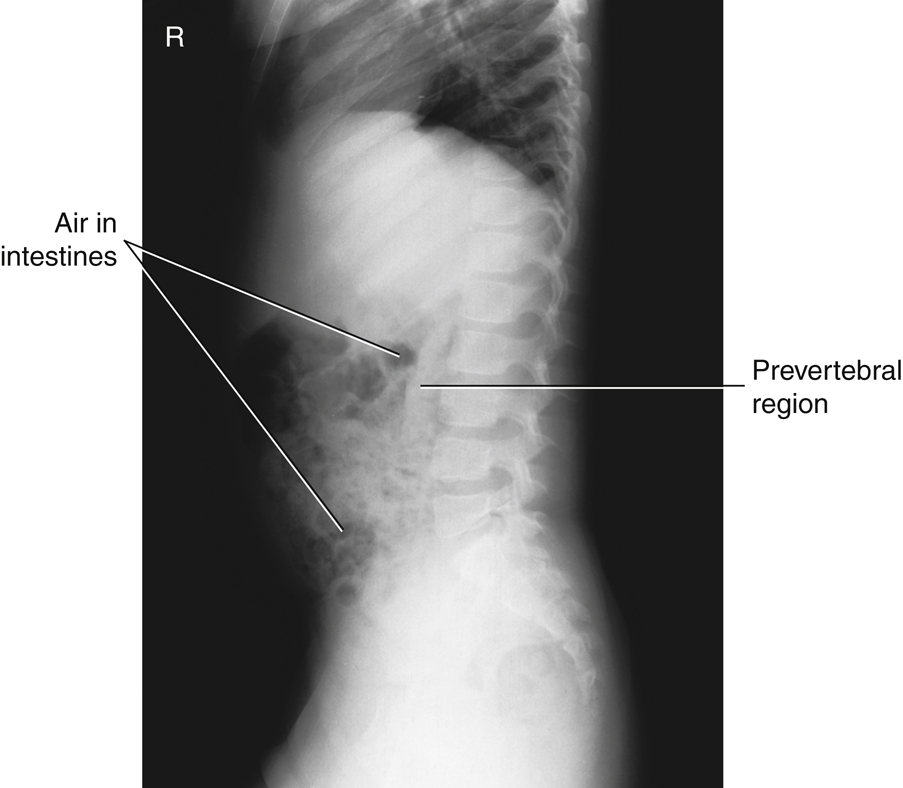
The two psoas major and minor muscles are located on either side of the lumbar vertebral column. The lateral borders of these two muscles should be faintly visible on a diagnostic abdominal image of a small to average-sized patient when correct exposure factors are used (see arrows, Figs. 3.1 and 3.2).
Abdominal Organ Systems
The various organ systems found within the abdominopelvic cavity are presented briefly in this chapter. Each system is described in greater detail in later chapters devoted to the specific systems.
Digestive System
The digestive system, along with its accessory organs, the liver, gallbladder, and pancreas, fills much of the abdominal cavity. The six organs of the digestive system are as follows:
Oral Cavity, Pharynx, and Esophagus
The oral cavity (mouth) and the pharynx (oropharynx and laryngopharynx) are common to the respiratory system and the digestive system, as illustrated in Fig. 2.4 (see Chapter 2). The esophagus is located in the mediastinum of the thoracic cavity.


Stomach and Small and Large Intestines
The three digestive organs within the abdominal cavity are the stomach and small and large intestines (Fig. 3.3).
Stomach
The stomach is the first organ of the digestive system that is located entirely within the abdominal cavity. The stomach is an expandable reservoir for swallowed food and fluids. The size and shape of the stomach vary depending on the volume of its contents and on the body habitus of the patient
Gastro is a common combining form denoting a relationship to the stomach (the Greek word gaster means “stomach”). The term gastrointestinal (GI) tract or system describes the entire digestive system, starting with the stomach and continuing through the small and large intestines.
Small Intestine
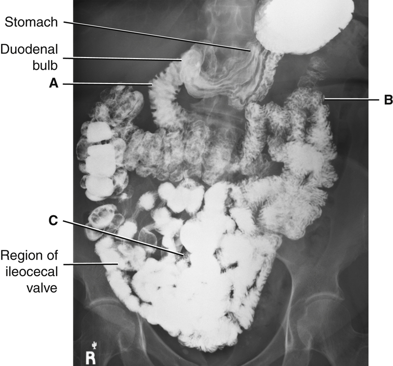
The small intestine continues from the stomach as a long, tubelike convoluted structure about 15 to 18 feet (4.5 to 5.5 m) in length. The three parts of the small intestine, as labeled in descending order in Figs. 3.4 and 3.5, are as follows: duodenum (doo″-o-de′-num) (A); jejunum (je-joo′-num) (B); and ileum (il′-eum) (C).
Duodenum (A)
The first portion of the small intestine, the duodenum, is the shortest, but widest, in diameter of the three segments. It is about 10 inches (25 cm) in length. When filled with contrast medium, the duodenum looks like the letter C. The proximal portion of the duodenum is the duodenal bulb, or cap. It has a characteristic shape that is usually well demonstrated on barium studies of the upper GI tract. Ducts from the liver, gallbladder, and pancreas drain into the duodenum to aid in digestive functions.
Jejunum and ileum (B and C)
The remainder of the small bowel lies in the central and lower abdomen. The first two-fifths, following the duodenum, are the jejunum, and the distal three-fifths are the ileum. The orifice (valve) between the distal ileum and the cecum portion of the large intestine is the ileocecal valve.
Radiographic Images of Stomach and Small Intestine
Air seldomly fills the entire stomach or small intestine on an abdominal image of a healthy, ambulatory adult. Fig. 3.5 demonstrates the stomach, small intestine, and proximal large intestine filled with radiopaque barium sulfate . Note the duodenal bulb and the long, convoluted loops of the three labeled parts of the small intestine located in the mid-abdomen and lower abdomen.
Large Intestine
The sixth and last organ of digestion is the large intestine, which begins in the right lower quadrant at the junction of the small intestine and the ileocecal valve. The portion of the large intestine below the ileocecal valve is a saclike portion named the cecum. The appendix (vermiform appendix) is attached to the posteromedial aspect of the cecum (Fig. 3.6).
The vertical portion of the large bowel, above the cecum, the ascending colon, joins the transverse colon at the right colic (kol′-ik, referring to colon) flexure. The transverse colon joins the descending colon at the left colic flexure. Alternative secondary names for the two colic flexures are hepatic (right) and splenic (left) flexures, based on their proximity to the liver and spleen, respectively.
The descending colon continues as the S-shaped sigmoid colon in the lower left abdomen. The rectum is the final 6 inches (15 cm) of the large intestine. The rectum ends at the anus, the sphincter muscle at the terminal opening of the large intestine.
As seen in body habitus illustrations, the shape and location of the large intestine varies greatly, with the transverse colon located high in the abdomen of wide hypersthenic body types and low in the abdomen of slender hyposthenic and asthenic body types (see also Chapter 13).


Spleen
The spleen is the part of the lymphatic system that, along with the heart and blood vessels, is part of the circulatory system. It is an important abdominal organ that occupies a space posterior and to the left of the stomach in the left upper quadrant, as shown in Fig. 3.7.
The spleen may be visualized faintly on abdominal images, particularly if the organ is enlarged. The spleen is a fragile organ and is sometimes lacerated during trauma to the lower left posterior rib cage.
Accessory Digestive Organs
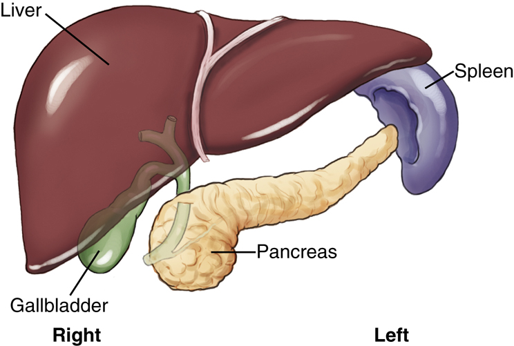
Three accessory organs of digestion, also located in the abdominal cavity, are the (1) pancreas, (2) liver, and (3) gallbladder. Accessory organs of digestion are outside the digestive tract but aid in digestion via the materials they secrete into the digestive tract.
Pancreas
The pancreas, which is not visualized on an abdominal image, is an elongated gland that is located posterior to the stomach and near the posterior abdominal wall, between the duodenum and the spleen. The average length is about 6 inches (12.5 cm). The head of the pancreas is nestled in the C-loop of the duodenum, and the body and tail of the pancreas extend toward the upper left quadrant of the abdomen. This relationship of the duodenum and the head of the pancreas sometimes is referred to as “the romance of the abdomen.”
The pancreas is part of the endocrine (internal) secretion system and the exocrine (external) secretion system. The endocrine portion of the pancreas produces essential hormones, such as insulin, which aids in controlling the blood sugar level of the body. As part of its exocrine functions, the pancreas produces large amounts (1½ quarts [1500 mL] daily) of digestive juices that move to the duodenum, through a main pancreatic duct, as needed for digestion.
Liver
The liver is the largest solid organ in the body, occupying the majority of the right upper quadrant of the abdomen. The liver has numerous functions, one of which is the production of bile that assists in the emulsification (breakdown) of fats.
Gallbladder
The gallbladder is a pear-shaped sac located posterior and inferior to the liver. If bile produced in the liver is not necessary at the current time for fat emulsification, it is stored and concentrated for future use in the gallbladder. The gallbladder contracts and releases the stored bile when stimulated by an appropriate hormone (cholecystokinin). In most cases, the gallbladder cannot be visualized without the use of contrast media. This is because the gallbladder and the biliary ducts are similar in tissue density and subject contrast to the surrounding abdominal soft tissues. The anatomy of the gallbladder and biliary ducts is described in greater detail in Chapter 12.
Cholelithiasis
Cholelithiasis is the presence of one or more calculi (gallstones) in the gallbladder.
1
Gallstones are composed of either cholesterol or a pigment made of bile salts, phosphate, and carbonate. Cholesterol-based gallstones are more commonly found in populations within the United States (80%), whereas the pigment-based stones are more commonly found in populations within Asia. These variances are most generally associated with diet.
Only about 20% of all gallstones contain enough calcium to allow visualization on an abdominal image. The majority of gallstones are radiolucent (not visible radiographically).
2
Alternative imaging modalities, such as diagnostic ultrasound, are better able to detect the presence and location of radiolucent gallstones.
CT Sectional Images
Computed tomography (CT) images through various levels of the abdomen are used to demonstrate anatomic relationships of the digestive organs and their accessory organs, in addition to the spleen.
Fig. 3.8 demonstrates an axial view of the upper abdomen at the level of T10 or T11 (tenth or eleventh thoracic vertebra) just below the diaphragm. Note the proportionately large size of the liver at this level in the right upper quadrant of the abdomen and the cross-sectional view through the stomach to the patient’s left of the liver. The spleen is visualized posterior to the stomach in the left upper quadrant of the abdomen.
Fig. 3.9 is an axial image inferior to Fig. 3.8 through the mid-abdomen at the approximate level of L2 (second lumbar vertebra). The abdominal aorta and inferior vena cava lie anterior to
the vertebral body. The kidneys are seen lateral to the psoas muscles. The dark air-filled portion of the transverse colon is on top (anteriorly), indicating that the patient was lying in a supine position for this CT scan.


Urinary System
The urinary system is another important abdominal system. Although this system is introduced in this chapter, it is discussed in detail in Chapter 14.
The urinary system comprises the following (Fig. 3.10):
Each kidney drains via its own ureter to the single urinary bladder. The bladder, which is situated superior and posterior to the symphysis pubis, stores urine. Under voluntary control, the stored urine passes to the exterior environment via the urethra. The two suprarenal (adrenal) glands of the endocrine system are located at the superomedial portion of each kidney. The bean-shaped kidneys are located on either side of the lumbar vertebral column. The right kidney is typically situated a little more inferior than the left kidney because of the presence of the liver on the right.
Waste materials and excess water are eliminated from the blood by the kidneys and are transported through the ureters to the urinary bladder.
Excretory or Intravenous Urogram
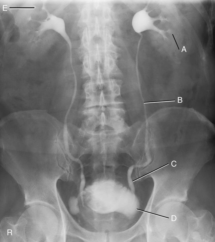
The kidneys are usually faintly demonstrated on an abdominal image because of a fatty capsule that surrounds each kidney. The contrast medium examination shown in Fig. 3.11 is an excretory or intravenous urogram (IVU), which is an examination of the urinary system performed with intravenous contrast medium. During this examination, the hollow organs of this system are visualized with the use of the contrast medium that has been filtered from the blood flow by the kidneys. The organs as labeled are the left kidney (A), the left proximal ureter (B), the left distal ureter (C) before emptying into the urinary bladder (D), and the right kidney (E).
NOTE:The term intravenous pyelogram (IVP) often was previously used for this examination. However, this is not an accurate term for this examination. The terms excretory urogram (EU) and intravenous urogram (IVU) are both current and correct terms.
Sectional Image
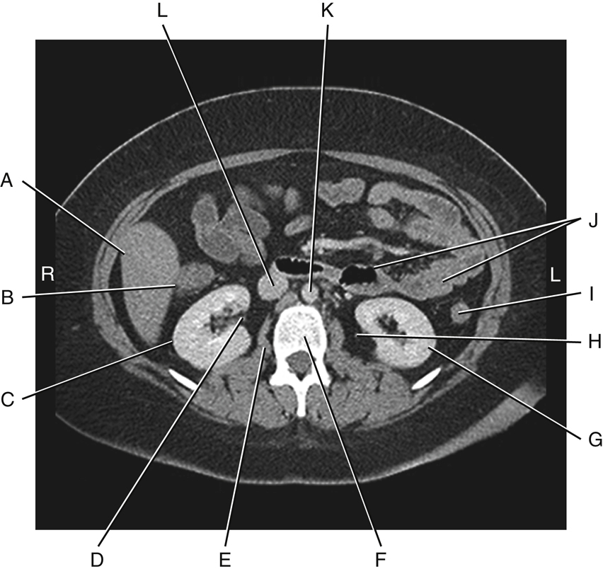
The sectional CT image (Fig. 3.12) may appear confusing at first because of the numerous small, odd-shaped structures that are demonstrated. However, as you study the relationships between these structures and imagine a thin “slice” view through the level of about L2–L3 of the drawings (see Fig. 3.10) and on the previous page (see Fig. 3.7), you may use the image to identify the anatomic positions and relationships of the structures previously discussed. The structures labeled in Fig. 3.12 are:
Two major blood vessels of the abdomen are also seen, labeled K and L. K is the large abdominal aorta, and L is the inferior vena cava.

Abdominal Cavity
Four important terms that describe the anatomy of the abdominal cavity appear on the drawings to the right and are described subsequently. These four terms are:
Peritoneum
Most of the abdominal structures and organs, in addition to the wall of the abdominal cavity in which they are contained, are covered to varying degrees by a large serous, double-walled, saclike membrane called the peritoneum. The total surface area of the peritoneum is approximately equal to the total surface area of the skin that covers the entire body.
A greatly simplified cross-section of the abdominal cavity is shown in Fig. 3.13. Two types of peritoneum exist: parietal and visceral. The two-layered peritoneum that adheres to the abdominal cavity wall is the parietal peritoneum, whereas the portion that covers an organ is the visceral peritoneum. The space or cavity between the parietal and visceral portions of the peritoneum is the peritoneal cavity. This space is only a potential cavity because normally it is filled with various organs, such as the loops of bowel. This cavity also contains some serous lubricating-type fluid, which allows organs to move against each other without friction. An abnormal accumulation of this serous fluid is a condition called ascites (see Clinical Indications section later in the chapter).
A layer of visceral peritoneum only partially covers certain organs that are more closely attached to the posterior abdominal wall (see Fig. 3.13). At this level, the ascending and descending colon, the aorta, and the inferior vena cava are only partially covered; therefore, this lining would not be considered mesentery, and these structures and organs are called retroperitoneal, as described in the next section.
Mesentery
The peritoneum forms large folds that bind the abdominal organs to each other and to the walls of the abdomen. Blood and lymph vessels, and the nerves that supply these abdominal organs, are contained within these folds of peritoneum. One of these double folds that hold the small intestine in place is known as mesentery. Mesentery is the double fold of peritoneum that extends anteriorly from the posterior abdominal wall to completely envelop a loop of small bowel. Mesentery is the specific term for a double fold of peritoneum that loosely connects the small intestine to the posterior abdominal wall (Fig. 3.14).
Omentum
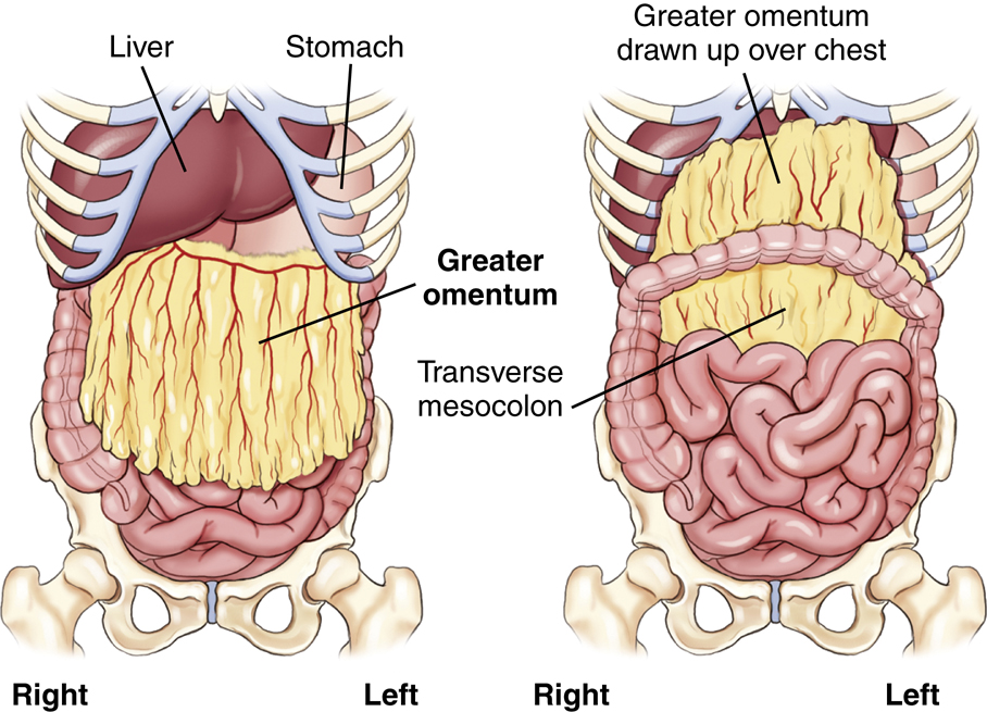
The term omentum refers to a specific type of double-fold peritoneum that extends from the stomach to another organ (see Fig. 3.14). The lesser omentum extends superiorly from the lesser curvature of the stomach to portions of the liver. The greater omentum connects the transverse colon to the greater curvature of the stomach inferiorly. The greater omentum drapes over the small bowel, then folds back on itself to form an apron along the anterior abdominal wall.
If one dissected the abdomen through the mid-anterior wall, the first structure encountered beneath the parietal peritoneum would be the greater omentum. Varying amounts of fat are deposited in the greater omentum, which serves as a layer of insulation between the abdominal cavity and the exterior. This is sometimes called the “fatty apron” because of its location and the amount of fat contained therein (Fig. 3.15).


Mesocolon
The peritoneum that attaches the colon to the posterior abdominal wall is the mesocolon. The prefix meso- is used to refer to mesentery-type folds from which other abdominal organs are suspended. Four forms of mesocolon exist, each named according to the portion of the colon to which it is attached: ascending, transverse, descending, and sigmoid or pelvic. The transverse mesocolon is shown in Fig. 3.15 as the visceral peritoneum that loosely connects the transverse colon to the posterior abdominal wall.
Greater Sac and Lesser Sac
The illustration in Fig. 3.16 shows the two parts of the peritoneal cavity. The major portion of the peritoneal cavity is the greater sac and is commonly referred to as simply the peritoneal cavity. A smaller portion of the upper posterior peritoneal cavity located posterior to the stomach is the lesser sac. This sac has a special name, the omentum bursa.
This drawing shows the mesentery connecting one loop of small intestine (ileum) to the posterior abdominal wall. A full drawing of a normal abdomen would have many loops of small bowel connected to the posterior wall by mesentery.
Retroperitoneal and Infraperitoneal Organs
The organs shown in Fig. 3.17 are considered either retroperitoneal (retro, meaning “backward” or “behind”) or infraperitoneal (infra, meaning “under” or “beneath”) in relation to the peritoneal cavity (Table 3.1).
Retroperitoneal Organs
Structures closely attached to the posterior abdominal wall that are retroperitoneal are the kidneys and ureters, adrenal glands, pancreas, C-loop of duodenum (aspect adjacent to head of pancreas), ascending and descending colon, upper rectum, abdominal aorta, and inferior vena cava.
These retroperitoneal structures are less mobile, within the abdomen, than other intraperitoneal organs. For example, Fig. 3.16 shows that the stomach, small intestine, and transverse colon are only loosely attached to the abdominal wall by long loops of different types of peritoneum; these structures change, or vary greatly, in their position within the abdomen compared with retroperitoneal or infraperitoneal structures.
Infraperitoneal Organs
Located under or beneath the peritoneum, in the true pelvis, are the lower rectum, urinary bladder, and reproductive organs.
Intraperitoneal Organs
Organs within the abdominal cavity that are partially or completely covered by some type of visceral peritoneum, but are not retroperitoneal or infraperitoneal, may be called intraperitoneal (intra, meaning “within”). These organs, which have been removed from the drawing in Fig. 3.17, include the liver, gallbladder, spleen, stomach, jejunum, ileum, cecum, and transverse and sigmoid colon.
Male Versus Female Peritoneal Enclosures
One significant difference exists between male and female peritoneal enclosures. The lower aspect of the peritoneum is a closed sac in the male but not in the female. In males, the lower peritoneal sac lies above the urinary bladder, totally separating the reproductive organs from the organs within the peritoneal cavity. In females, the uterus, uterine (fallopian) tubes, and ovaries pass directly into the peritoneal cavity (see Fig. 3.16).


TABLE 3.1
Quadrants and Regions
To facilitate description of the locations of various organs or other structures within the abdominopelvic cavity, the abdomen may be divided into four quadrants or nine regions.
Four Abdominal Quadrants
If two imaginary perpendicular planes (at right angles) were passed through the abdomen at the umbilicus (or navel), they would divide the abdomen into four quadrants (Figs. 3.18 and 3.19). One plane would be transverse through the abdomen at the level of the umbilicus, which on most people is at the level of the intervertebral disk between L4 and L5 (fourth and fifth lumbar vertebrae), which is at about the level of the iliac crests on a female.
The vertical plane would coincide with the midsagittal plane, or midline, of the abdomen and would pass through both the umbilicus and the symphysis pubis. These two planes would divide the abdominopelvic cavity into four quadrants: right upper quadrant (RUQ), left upper quadrant (LUQ), right lower quadrant (RLQ), and left lower quadrant (LLQ).
NOTE:The four-quadrant system is used most frequently in imaging for localizing a particular organ or for describing the location of abdominal pain or other symptoms (Table 3.2).
TABLE 3.2
| RUQ | LUQ | RLQ | LLQ |
|---|---|---|---|
|
Liver
Gallbladder
Right colic (hepatic) flexure
Duodenum (C-loop)
Head of pancreas
Right kidney
Right suprarenal gland
|
Spleen
Stomach
Left colic (splenic) flexure
Tail of pancreas
Left kidney
Left suprarenal gland
|
Ascending colon
Appendix (vermiform)
Cecum
2⁄3 of ileum
Ileocecal valve
|
Descending colon
Sigmoid colon
2⁄3 of jejunum
|

Nine Abdominal Regions
The abdominopelvic cavity also can be divided into nine regions through the use of two horizontal or transverse planes and two vertical planes. The two transverse/horizontal planes are the transpyloric plane and the transtubercular plane. The two vertical planes are the right and left lateral planes (Fig. 3.20).
The transpyloric plane is at the level of the lower border of L1 (first lumbar vertebra), and the transtubercular plane is at the level of L5. The right and left lateral planes are parallel to the midsagittal plane and are located midway between it and each anterior superior iliac spine (ASIS).
Names of Regions
The names of these nine regions are given in the following list. Technologists should be familiar with the locations and names of these nine regions. However, in general, locating most structures and organs within the four-quadrant system is sufficient for imaging purposes because of variables that affect specific locations of organs, such as body habitus, body position, and age (see organ outlines in Fig. 3.20 for general locations of organs within these nine regions).


Topographic Landmarks
Abdominal borders and organs within the abdomen are not visible from the exterior, and because these soft tissue organs cannot be palpated directly, certain bony landmarks are used for this purpose.
NOTE:Palpation must be performed gently because the patient may have painful or sensitive areas within the abdomen and pelvis. Also, ensure the patient is informed of the purpose of palpation before beginning.
Seven Landmarks of the Abdomen
The following seven palpable landmarks are important in positioning the abdomen or locating organs within the abdomen (Figs. 3.21 and 3.22). You should practice finding these bony landmarks on yourself before attempting to locate them on another person or on a patient for the first time.
Positioning for abdominal radiographs in AP or posteroanterior (PA) projections requires quick and accurate localization of these landmarks on all patient body types.
- 1. Xiphoid process (level of T9–T10): The tip of the xiphoid process is the most inferior process of the sternum. This landmark can be palpated best by first gently pressing on the soft abdomen below the distal sternum, then moving upward carefully against the firm, distal margin of the xiphoid process. This landmark approximates the superior anterior portion of the diaphragm, which is also the superior margin of the abdomen. However, this is not a primary landmark for positioning the abdomen because of variation in body types and the importance of including all of the lower abdomen on images of the abdomen.
- 2. Inferior costal (rib) margin (level of L2–L3): This landmark is used to locate upper abdominal organs, such as the gallbladder and stomach.
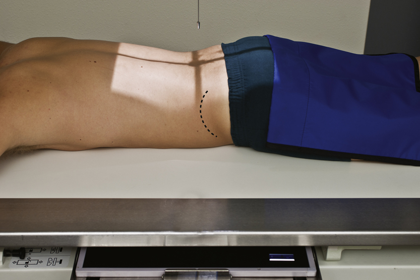
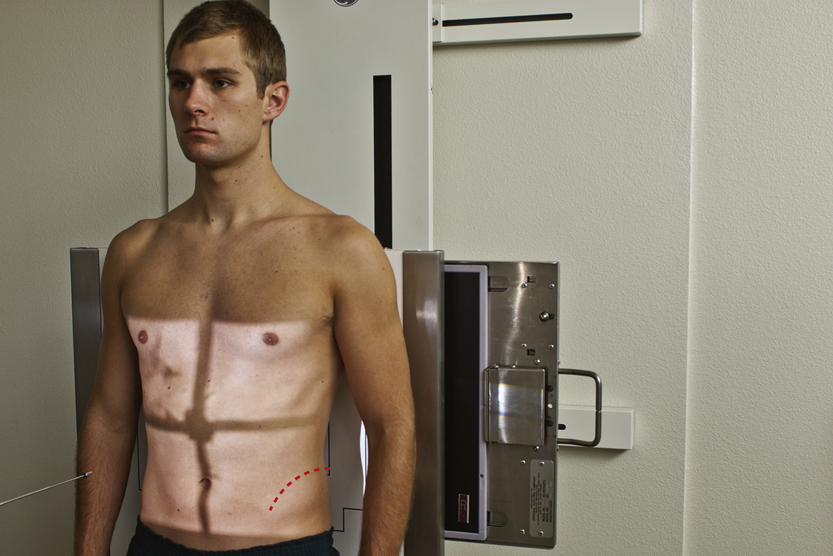
- 3. Iliac crest (level of L4–L5 vertebral interspace): The crest of the ilium is the uppermost portion of the curved border of the ilium. The iliac crest can be palpated easily by pressing inward and downward along the mid-lateral margin of the abdomen. The uppermost, or most superior, portion of this crest is the most commonly used abdominal landmark and corresponds approximately to the level of the mid-abdominopelvic region, which is also at or just slightly below the level of the umbilicus on most people.
NOTE: Ensuring the entire upper abdomen, including the diaphragm, is included on the radiographic image may require centering about 2 inches (5 cm) above the level of the crest for most patients, which subsequently may cause some of the important lower abdomen not to be included in the image. Therefore, a second projection centered lower would be required to include this lower region.
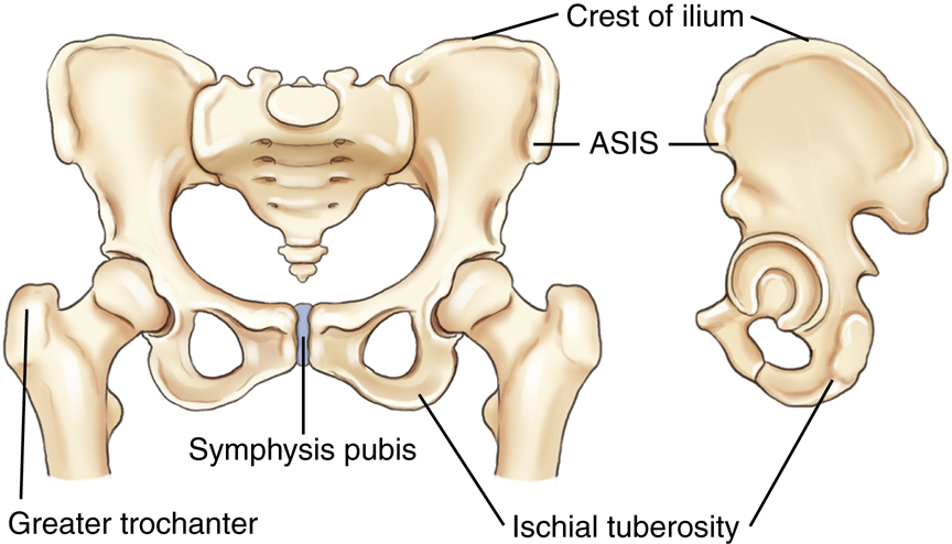
- 4. Anterior superior iliac spine: The ASIS can be found by locating the iliac crest, then palpating anteriorly and inferiorly until a prominent projection or “bump” is felt (more prominent on females). This landmark is commonly used for positioning of pelvic and vertebral structures but can also serve as a secondary landmark for general abdominal positioning (Fig. 3.23).
- 5. Greater trochanter: This landmark is more easily palpated on thin patients. Gentle but very firm palpation is required to feel the movement of the trochanter with one hand, while rotating the leg internally and externally at the knee area with the other hand. This is not as precise a landmark as the other bony landmarks of the pelvis, but the prominence of the greater trochanter is at about the same level as the superior border of the symphysis. With practice, the greater trochanter can be used as a secondary landmark for abdominal positioning.
- 6. Symphysis pubis: The symphysis pubis is the anterior junction (joint) of the two pelvic bones. The most superior anterior portion of the pubis can be palpated when the patient is in a supine position. This landmark corresponds to the inferior margin of the abdomen. However, palpation of this area may be embarrassing to some patients and palpating the greater trochanter may be a better option.
- 7. Ischial tuberosity: This landmark can be used to determine the lower margin on a PA abdomen with the patient in a prone position. These two bony prominences, which can be palpated most easily on thin patients, bear most of the weight of the trunk when one is seated. The lower margins of the ischial tuberosities are about 0.4 to 1.5 inches (1 to 4 cm) below or distal to the symphysis pubis. This landmark may be used for positioning a PA projection of the colon when the rectal area is to be included on the IR. However, this may be uncomfortable and embarrassing for the patient, and other landmarks can and should be used when possible.


Radiographic Positioning
Patient Preparation
Patient preparation for abdominal imaging includes removal of all clothing and any radiopaque items that may be in the area to be imaged. The patient should wear a hospital gown with the opening and ties in the back (if this type of gown is used). Shoes and socks may remain on the feet. Generally, no patient instructions are required before the examination unless contrast media studies are also scheduled.
General Positioning Considerations
Make patients as comfortable as possible on the radiographic table. A pillow under the head and support under the knees enhance comfort for a supine abdomen. Place clean linen on the table and cover patients to keep them warm and to protect their modesty.
Breathing Instructions
A key factor in quality abdominal imaging is the prevention of motion. Motion may result from voluntary movement, such as breathing, or from involuntary movement, such as peristaltic action of the bowel. The difference between these two types of motion is illustrated in Chapter 1. However, to prevent any potential motion in abdominal radiography, the shortest exposure time possible should be used.
A second method to prevent voluntary motion is by providing careful breathing instructions to the patient. Most abdominal radiographs are taken on expiration; the patient is instructed to “take in a deep breath—let it all out and hold it—do not breathe.” Before making the exposure, ensure the patient is following instructions and sufficient time has been allowed for all breathing movements to cease.
Abdominal images are exposed on expiration, with the diaphragm in a superior position for better visualization of abdominal structures.
Image Markers
Correctly placed R and L markers corresponding to the appropriate side of the patient and “up side” indicator markers, such as short arrows, for erect and decubitus projections should be visible without superimposing abdominal structures. The marker(s) must be placed on the IR before exposure. It is not acceptable practice to indicate the side of the body postexposure.
Radiation Protection
Good radiation protection practices are especially important in abdominal imaging because of the proximity of the radiation-sensitive gonadal organs.
Repeat Exposures
Careful positioning and selection of correct exposure factors are means to reduce unnecessary exposure from repeat examinations. Providing clear breathing instructions also assists in eliminating repeat exposures that often result from motion caused by breathing during the exposure.
Close Collimation
For abdominal radiographs of small patients, some side collimation to skin borders is possible; ensure it does not exclude any pertinent abdominal anatomy.
Collimation on the top and bottom for adults should be adjusted directly to the margins of the IR, allowing for divergence of the x-ray beam.
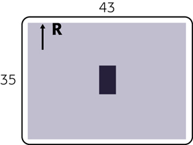
NOTE: Vertical collimation (up/down) may result in collimating off essential anatomy on average-sized adults when using a typical 14 × 17-inch (35 × 43-cm) field size.
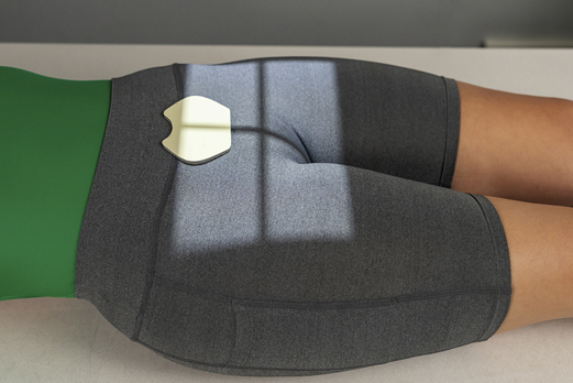
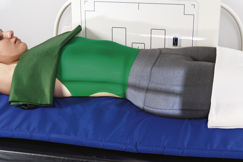
Gonadal Shielding
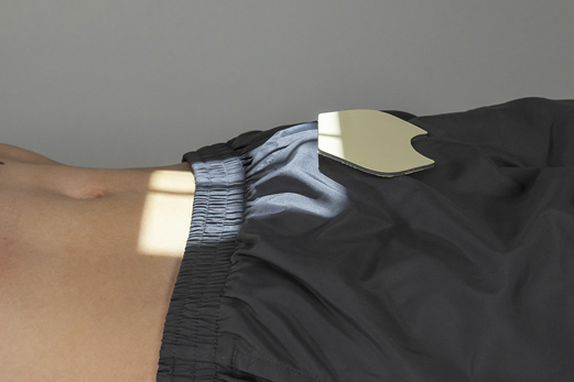
For abdominal images, gonadal shields should be used for male patients, with the upper edge of the shield carefully placed at the pubic symphysis (Fig. 3.24). For female patients, gonadal shields should be used only when such shields do not obscure essential anatomy in the lower abdominopelvic region (Fig. 3.25). Generally, the decision to shield female gonads on abdominal radiographs should be made by a physician to determine whether essential anatomy would be obscured. The top of an ovarian shield should be at or slightly above the level of ASIS, and the lower border should be at the symphysis pubis.
Pregnancy Protection
See Chapter 1, regarding safeguards for potential early pregnancies with abdominal or pelvic projections.
Exposure Factors
The principal exposure factors for abdominal images are as follows:
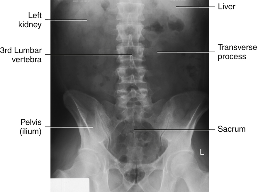
Correctly exposed abdominal images on an average-sized patient should faintly demonstrate the lateral borders of the psoas muscles, lower liver margin, kidney outlines, and the transverse processes of the lumbar vertebrae. The kVp should be set at a level that will allow for appropriate penetrability to visualize various abdominal structures, including possible small semiopaque stones in the gallbladder or kidneys.
Special Patient Considerations
Pediatric Applications
Motion prevention is of utmost importance in pediatric patients, and short exposure times are essential. Children younger than 13 years of age require a reduction in kVp and mAs based on measured part thickness. Confirmed technique factors for children of various sizes and ages for the equipment that is being used should always be available to minimize repeat exposures. Grids may not be necessary for pediatric abdominal radiographic procedures (if measured thickness is less than 10 cm).
Geriatric Applications
Older patients often require extra care and patience in explaining what is expected of them. Careful breathing instructions are essential, as is assistance in helping patients move into the required position. Extra radiolucent padding under the back and buttocks for thin patients and blankets to keep patients warm add greatly to their comfort on supine abdomen radiographic procedures.
Bariatric Patient Considerations
Positioning of the bariatric patient for abdomen projections is similar to that for the sthenic patient. The challenge is often in palpation for bony landmarks, such as the iliac crest and symphysis pubis, on the morbidly obese patient. The technologist may need to move folds of adipose tissue and skin to locate these landmarks, which may be embarrassing for the patient. It may be more feasible to use the xiphoid process (T9–T10) or the lower costal margin (L2–L3) to determine the upper margin of the IR. The ASIS may be easier to palpate to determine the lower abdomen margin. Some technologists may use the umbilicus (“belly button”) as an alternative to the iliac crest. However, due to extension of the abdomen, skin folds, and possible past surgeries, this often proves to be an inaccurate landmark.
It is critical to image the entire abdomen to the skin margins because the large intestine often extends the width of the abdomen. This is accomplished by taking two exposures of the abdomen with a landscape alignment to capture any abnormal anatomy, gas patterns, or pathology. The first projection would image the upper abdomen (top of IR at the level of the xiphoid process), whereas the second projection would slightly overlap about 1 to 2 inches (3 to 5 cm) to visualize all abdominal anatomy. The bottom of the second IR should be placed at the level of the symphysis pubis to image the lower abdominopelvic structures (Figs. 3.26 and 3.27). This alteration in the routine protocol would be recommended for the supine abdomen (KUB) and erect abdomen studies.


Digital Imaging Considerations
The guidelines that should be followed with digital imaging of the abdomen as described in this chapter are summarized as follows:
- 1. Four-sided collimation: Collimation to the body part being imaged and accurate centering are most important in digital imaging of the abdomen.
- 2. Exposure factors: It is important that the ALARA principle (as low as reasonably achievable) be followed in regard to patient exposure to radiation and that the lowest exposure factors required to obtain a diagnostic image be used. This includes the highest kVp and the lowest mAs that result in desirable image quality.
- 3. Post-processing evaluation of exposure indicator: The exposure indicator on the final processed image must be checked to verify that the exposure factors used were in the correct range to ensure optimal quality with the least amount of radiation to the patient. The technologist should assess these after each image.
Alternative Modalities
CT and MRI
CT and magnetic resonance imaging (MRI) are very useful in the evaluation and early diagnosis of small neoplasms involving abdominal organs, such as the liver and pancreas. With the use of intravenous, iodinated contrast media, CT imaging can discriminate between a simple cyst and a solid neoplasm.
Both CT and MRI also provide valuable information in assessing the extent to which neoplasms have spread to surrounding tissues or organs. For example, MRI may be used to demonstrate blood vessels within neoplasms and to assess their relationship and involvement with surrounding organs without the need for contrast media injection.
MRI is also used to visualize the biliary and pancreatic ducts. Endoscopic retrograde cholangiopancreatography (ERCP), a fluoroscopic procedure in which a contrast medium is injected endoscopically, is used to visualize the biliary and pancreatic ducts as well (described in Chapter 19).
Sonography
Ultrasound has become the method of choice when imaging the gallbladder for detection of gallstones (in the gallbladder or bile ducts). Ultrasound is of limited use in the evaluation of the hollow viscus of the GI tract for bowel obstruction or perforation, but along with CT, it is very useful in detecting and evaluating lesions or inflammation of soft tissue organs such as the liver or pancreas. Ultrasound is widely used, along with CT, for demonstrating abscesses, cysts, or tumors involving the kidneys, ureters, or bladder.
Ultrasound with graded compression, in combination with clinical evaluation, can be used successfully to diagnose acute appendicitis; this is the recommended approach for pediatric patients. However, CT is considered the ideal imaging modality to demonstrate an abscess or thickened wall surrounding the inflamed appendix. CT, with the use of intravenous contrast media, can demonstrate the location, extent, and degree of involvement of the surrounding tissues.
5
Nuclear Medicine
Nuclear medicine is useful as a noninvasive means of evaluating GI motility and reflux as related to possible bowel obstruction. It is also useful for evaluation of suspected lower GI bleeding.
With the injection of specific radionuclides, nuclear medicine imaging can be used to examine the entire liver, the major bile ducts and gallbladder.
Clinical Indications
An AP supine image of the abdomen (KUB) is generally taken before contrast medium is introduced into the various abdominal organ systems for evaluation and diagnosis of diseases and conditions involving these systems (Table 3.3). Clinical indications and terms specifically related to each of these systems are provided in Chapters 12 and 13.
The acute abdomen series, as described in this chapter, is performed most commonly to evaluate and diagnose conditions or diseases related to bowel obstruction or perforation. This evaluation requires visualization of air-fluid levels and possible intraperitoneal “free” air with the use of a horizontal beam and erect or decubitus body positions. Following are terms and pathologic diseases or conditions that are related to the acute abdominal series examination.
- Ascites (ah-si′-tez) is an abnormal accumulation of fluid in the peritoneal cavity of the abdomen. It is usually caused by long-standing (chronic) conditions such as cirrhosis of the liver or by metastatic disease to the peritoneal cavity.
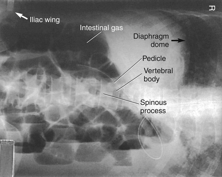
- Pneumoperitoneum refers to free air or gas in the peritoneal cavity. This is a serious condition for which surgery is required when it is caused by perforation of a gas-containing viscus, such as a gastric or duodenal ulcer. It also can be caused by trauma that penetrates the abdominal wall. Small amounts of residual air may be evident radiographically 2 to 3 weeks after abdominal surgery. Air is best demonstrated with a horizontal beam, erect abdomen, or chest image, with which even a small amount of free air can be seen as it rises to the highest position under the diaphragm.
- Dynamic (with power or force) or mechanical bowel obstruction is the complete or nearly complete blockage of the flow of intestinal contents. Causes include the following:
-
- • Fibrous adhesions: The most common cause of mechanically based obstruction, in which a fibrous band of tissue interrelates with the intestine, creating a blockage.
- • Crohn’s (krons) disease: Also known as regional enteritis, a chronic inflammation of the intestinal wall that results in bowel obstruction in at least half of affected patients. The cause is unknown. Crohn’s disease is most common in young adults and is characterized by loops of small intestine joined by fistulas or connected openings with adjacent loops of intestine. The two most common sites of intestinal involvement in Crohn’s disease are the terminal ileum and proximal colon. 5
- • Intussusception: The telescoping of a section of bowel into another loop, which creates an obstruction. Intussusception is most common in the distal small intestine region (terminal ileum), and it is more common in children than in adults. This condition requires treatment within 48 hours to prevent necrosis (tissue death).
-
TABLE 3.3
Summary of Clinical Indications Condition or Disease Most Common Radiographic Examination Possible Radiographic Appearance Exposure Factor Adjustment a Ascites Acute abdomen series General abdominal haziness Increase, depending on severity (+ or + +) Pneumoperitoneum (air in peritoneal cavity) Acute abdomen series—erect chest or abdomen Thin, crest-shaped radiolucency under dome of right hemidiaphragm on erect Decrease (−) Dynamic (Mechanical Bowel) Obstruction Fibrous adhesions Acute abdomen series Distended loops of air-filled small intestine Decrease, depending on severity of distention (− or − −) Crohn’s disease Acute abdomen series Distended loops of air-filled small intestine (cobblestone appearance) Decrease, depending on severity of distention (− or − −) Intussusception (most common in children) Acute abdomen series Air-filled “coiled spring” appearance Decrease (−) Volvulus (most common in sigmoid colon) Acute abdomen series Large amounts of air in sigmoid with tapered narrowing at site of volvulus (beak sign) Slight decrease (−) Ileus (nonmechanical obstruction), adynamic or paralytic Acute abdomen series Large amounts of air in entire dilated small and large intestine with air-fluid levels visualized Decrease, depending on severity of distention (− or − −) Ulcerative Colitis Severe case may lead to toxic megacolon and bowel perforation AP abdomen Deep air-filled mucosal protrusions of colon wall, usually in rectosigmoid region Decrease (−) Acute abdomen series for possible free air (barium enema contraindicated) Dilated loop of colon Decrease (−) 
- • Volvulus: The twisting of a loop of intestine, which creates an obstruction. Volvulus may require surgery for correction.
- Ileus (nonmechanical bowel obstruction) is categorized as adynamic (without power or force) ileus and most frequently is caused by peritonitis, or paralytic (paralysis) ileus, which is caused by a lack of intestinal motility. Paralytic ileus occurs frequently in postoperative patients, usually 24 to 72 hours after abdominal surgery. In contrast to mechanical obstruction, it rarely leads to perforation, and the radiographic appearance is characterized by a large amount of air and fluid, with air-fluid levels visible in a significantly dilated small and large intestine and no visible distinct point of obstruction (in contrast to a mechanical obstruction).
- Ulcerative colitis is a chronic disease involving inflammation of the colon that occurs primarily in young adults and most frequently involves the rectosigmoid region. In some cases, it becomes a very severe acute process, causing serious complications, such as toxic megacolon (extreme dilation of a segment of colon) with potential perforation into the peritoneal cavity. Barium enema is strongly contraindicated with symptoms of toxic megacolon.
Routine and Special Projections
AP Projection: Supine Position—Abdomen
KUB
Clinical Indications
Technical Factors
Shielding
Shield radiosensitive tissues outside region of interest.
Patient Position
Part Position

- • Center of IR to level of iliac crests, with bottom margin at symphysis pubis (Fig. 3.28) (see NOTES)
- • No rotation of pelvis or shoulders (check that both ASIS are the same distance from the tabletop)
CR
Recommended Collimation
14 × 17 inches (35 × 43 cm), field of view or collimate on four sides to anatomy of interest
Respiration
Make the exposure at end of expiration (allow about 1 second delay after expiration to allow involuntary motion of bowel to cease).
NOTES:A tall hyposthenic or asthenic patient may require two images placed portrait (Fig. 3.30)—one centered lower to include the symphysis pubis (bottom margin of first IR at symphysis) and the second centered higher to include the upper abdomen and diaphragm (top margin of second IR at xiphoid).
A broad hypersthenic patient may require two 14 × 17-inch (35 × 43-cm) IRs placed landscape, one centered lower to include the symphysis pubis and the second for the upper abdomen, with a minimum of 1 to 2 inches (3 to 5 cm) overlap (Fig. 3.29).

PA Projection—Prone Position: Abdomen
Clinical Indications
NOTE:This projection is less desirable than AP if the kidneys are of primary interest because of the increased object–image receptor distance (OID). However, this projection is helpful to lower exposure due to tissue compression as it leads to reduced part thickness.
Technical Factors

Shielding
Shield radiosensitive tissues outside region of interest
Patient Position
- • Prone with midsagittal plane of body centered to midline of table or IR (Fig. 3.33)
- • Legs extended with support under ankles
- • Arms up beside head; clean pillow provided
Part Position
CR
Recommended Collimation
14 × 17 inches (35 × 43 cm), field of view or collimate on four sides to anatomy of interest
Respiration
Make exposure at end of expiration.
NOTE:Tall, asthenic patients may require two images placed portrait; broad, hypersthenic and bariatric patients may require two images placed landscape.
Lateral Decubitus Position (AP Projection)—Abdomen
Clinical Indications
Important: Patient should be on his or her side a minimum of 5 minutes before exposure (to allow air to rise or abnormal fluids to accumulate); 10 to 20 minutes is preferred, if possible, for best visualization of potentially small amounts of intraperitoneal air
Left lateral decubitus position best visualizes free intraperitoneal air in the area of the liver in the right upper abdomen away from the gastric bubble
Technical Factors
Marker: Place arrow or other appropriate marker to indicate “up” side.
Shielding
Shield radiosensitive tissues outside region of interest.
Patient Position
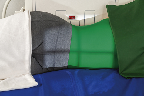
- • Lateral recumbent on radiolucent pad, firmly against table or vertical grid device (with wheels on cart locked so as not to move away from table)
- • Patient on firm surface, such as a cardiac or back board, positioned under the sheet to prevent sagging and anatomy cutoff (Fig. 3.36)
- • Knees partially flexed, one on top of the other, to stabilize patient
- • Arms up near head; clean pillow provided
Part Position
- • Adjust patient and cart/table so that center of IR and CR are approximately 2 inches (5 cm) above level of iliac crests (to include diaphragm). Upper margin of IR is approximately at level of axilla.
- • Ensure no rotation of pelvis or shoulders.
- • Adjust height of IR to center midsagittal plane of patient to center of IR, but ensure that upside of abdomen is clearly included on the IR.

CR
Recommended Collimation
Respiration
Make exposure at end of expiration.

AP Projection: Erect Position—Abdomen
Clinical Indications
Perform erect abdominal image first if the patient comes to the department ambulatory or in a wheelchair in an erect position.
Technical Factors
Marker: Include erect marker on IR.

Shielding
Patient Position
Part Position
- • Do not rotate pelvis or shoulders.
- • Adjust height of IR so that the center is approximately 2 inches (5 cm) above iliac crest (to include diaphragm), which for the average patient places the top of the IR approximately at the level of the axilla (Fig. 3.39).
CR
Recommended Collimation
Respiration
Exposure should be made at end of expiration.
NOTE:Patient should be upright a minimum of 5 minutes, but 10 to 20 minutes is desirable, if possible, before exposure for visualizing small amounts of intraperitoneal air. If a patient is too weak to maintain an erect position, a lateral decubitus should be performed. For hypersthenic patients, two landscape IRs may be required to include the entire abdomen.

Dorsal Decubitus Position (Right or Left Lateral)—Abdomen
Clinical Indications
Technical Factors

Shielding
Patient Position
- • Supine on radiolucent pad, side against table or vertical grid device; secure cart so that it does not move away from table or grid device.
- • Ensure that neither the patient nor the cart is tilted in relation to the IR.
- • Pillow under head, arms up beside head; support under partially flexed knees may be more comfortable for the patient (Fig. 3.42).
Part Position
- • Adjust patient and cart so that center of IR and CR is at level of iliac crest or 2 inches (5 cm) above iliac crest to include diaphragm.
- • Ensure that no rotation of pelvis or shoulders exists (both ASIS should be the same distance from tabletop).
- • Adjust height of IR to align midcoronal plane with centerline of IR.
CR
Recommended Collimation
Collimate to upper and lower abdomen soft tissue borders. Close collimation is important because of increased scatter produced by exposure of tissue outside the area of interest
Respiration
Exposure is made at end of expiration.
NOTE:This may be taken as a right or left lateral; appropriate R or L lateral marker should be used, indicating the side closest to IR.
Lateral Position—Abdomen
Clinical Indications
Technical Factors

Shielding
Patient Position
- • Patient in lateral recumbent position on right or left side, pillow for head
- • Elbows flexed, arms up, knees and hips partially flexed, pillow between knees to maintain a lateral position (Fig. 3.45)
- • Ensure patient is not tilted
Part Position
CR
Recommended Collimation
Collimate closely to upper and lower IR borders and to anterior and posterior skin borders to minimize scatter.
Respiration
Suspend breathing on expiration.

Acute Abdominal Series—Acute Abdomen
(1). AP Supine, (2) Erect (or Lateral Decubitus) Abdomen, (3) PA Chest
Departmental Routine
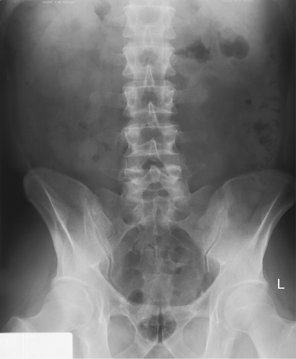
The acute abdomen series typically consists of three projections: AP supine abdomen (Fig. 3.48), AP erect abdomen, and a PA chest projection. However, acute abdomen routines may vary, depending on the institution. Students and technologists should be aware of the routine for their departments.
The PA chest is commonly included in the acute abdomen series because the erect chest allows free intraperitoneal air under the diaphragm to be visualized. The erect abdomen also visualizes free air, if the IR is centered high enough to include the diaphragm; however, the exposure technique for the chest best visualizes small amounts of this free air if present.
NOTE:Acute abdomen routines for pediatric patients generally include only an AP supine abdomen and one horizontal beam projection to demonstrate air-fluid levels. For patients younger than 2 or 3 years of age, a left lateral decubitus may be difficult to obtain, and an AP erect abdomen with an immobilization device such as a Pigg-O-Stat (Modern Way Immobilizers, Inc, Clifton, Tennessee) is preferred (see Chapter 16).
Specific Clinical Indications for Acute Abdominal Series
- • Ileus (nonmechanical small bowel obstruction) or mechanical ileus (obstruction of bowel from hernia, adhesions)
- • Ascites (abnormal fluid accumulation in abdomen)
- • Perforated hollow viscus (e.g., bowel or stomach, evident by free intraperitoneal air)
- • Intra-abdominal mass (neoplasms—benign or malignant)
- • Postoperative (abdominal surgery)
Perform erect images first if patient comes to the department in an erect position.
Positional Guidelines
Review positional guidelines as described on preceding pages for AP supine, AP erect, and PA chest.
Patient and Part Positioning
Most department routines for the erect abdomen include centering high to demonstrate possible free intraperitoneal air under the diaphragm, even if a PA chest is included in the series.
Breathing Instructions
Chest projections exposed on full inspiration; abdomen exposed on expiration.
CR
CR to level of iliac crest on supine and approximately 2 inches (5 cm) above level of crest to include diaphragm on erect or decubitus radiographs
NOTES:Left lateral decubitus replaces erect position if the patient is too ill to stand.
Horizontal beam is necessary for visualization of air-fluid levels.
Erect PA chest (Fig. 3.49) or AP erect abdomen (Fig. 3.50) best visualizes free air under diaphragm.
For left lateral decubitus, patient should be on the right side for a minimum of 5 minutes before exposure (10 to 20 minutes preferred) to demonstrate potential small amounts of intraperitoneal air (Fig. 3.51).


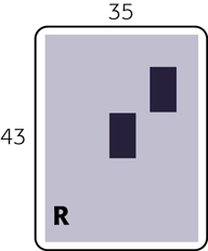
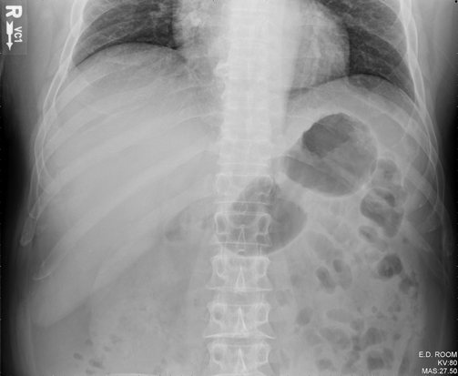
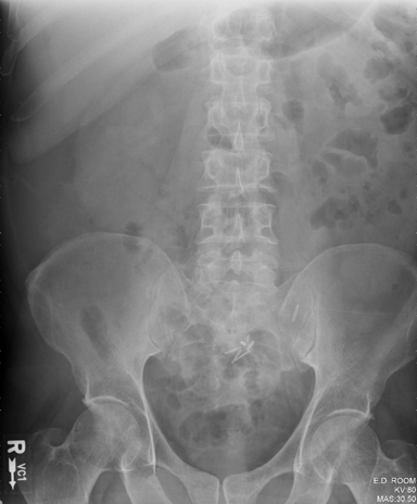
Radiographs for Critique
This section consists of an ideal projection (Image A) along with one or more projections that may demonstrate positioning and/or technical errors. Critique Figures C3.52 through C3.54. Compare Image A to the other projections and identify the errors. While examining each image, consider the following questions:
- 1. Is all essential anatomy demonstrated on the image?
- 2. What positioning errors are present that compromise image quality?
- 3. Are technical factors optimal?
- 4. Is there evidence of collimation and pre-exposure anatomical side markers visible on the image?
- 5. Do these errors require a repeat exposure?
Feedback for each set of images is located on the faculty Evolve site.

C courtesy of Dr. Jeremy Jones, Radiopaedia.org, rID: 34067.

C courtesy of Abdominal X-ray Interpretation. Available at https://geekymedics.com/abdominal-x-ray-interpretation/.
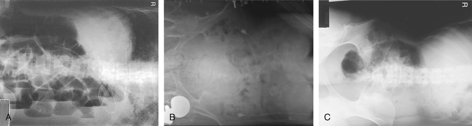
A modified from McQuillen Martensen K: Radiographic image analysis, ed 4, St Louis, 2015, Saunders; B copyright Nicholas Joseph Jr. [Radiograph #95; http://www.ceessentials.net/article24.html].