Chapter 5: Humerus and Shoulder Girdle
Contributions By Christopher I. Wertz, MSRS, RT(R)
Contributors to Past Editions John P. Lampignano, MEd, RT(R)(CT), Dan L. Hobbs, MSRS, RT(R)(CT)(MR), Linda S. Lingar, MEd, RT(R)(M), and Donna Davis, MEd, RT(R)(CV)
Radiographic Anatomy
Upper Limb (Extremity)
The hand, wrist, forearm, and elbow of the upper limb were described in Chapter 4. This chapter describes the humerus and the shoulder girdle, which includes the clavicle and scapula (
Fig. 5.1
).
Humerus
The humerus is the largest and longest bone of the upper limb. Its length on an adult equals approximately one-fifth of body height. The humerus articulates with the scapula (shoulder blade) at the shoulder joint. The anatomy of the distal humerus and of the elbow joint was described in Chapter 4.
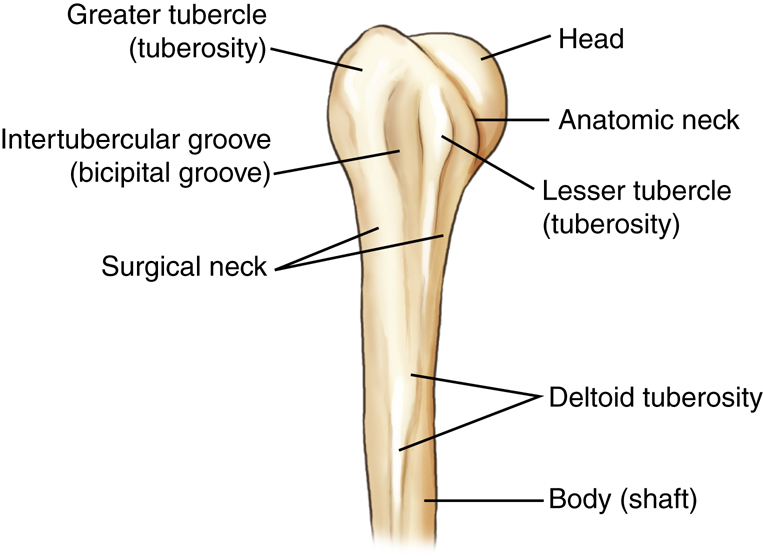
Proximal Humerus
The proximal humerus is the part of the upper arm that articulates with the scapula, making up the shoulder joint. The most proximal part is the rounded head of the humerus. The slightly constricted area directly below and lateral to the head is the anatomic neck, which appears as a line of demarcation between the rounded head and the adjoining greater and lesser tubercles.
The process directly below the anatomic neck on the anterior surface is the lesser tubercle (tu′-ber-k′l). The larger lateral process is the greater tubercle, to which the pectoralis major and supraspinatus muscles attach. The deep groove between these two tubercles is the intertubercular (in″-ter-tu-ber′-ku-lar) sulcus (bicipital groove). The tapered area below the head and tubercles is the surgical neck, and distal to the surgical neck is the long body (shaft) of the humerus.
The surgical neck is so named because it is the site of frequent fractures requiring surgery. Fractures at the thick anatomic neck are rarer.
The deltoid tuberosity is the roughened raised triangular elevation along the anterolateral surface of the body (shaft) to which the deltoid muscle is attached.
Anatomy of Proximal Humerus on Radiograph
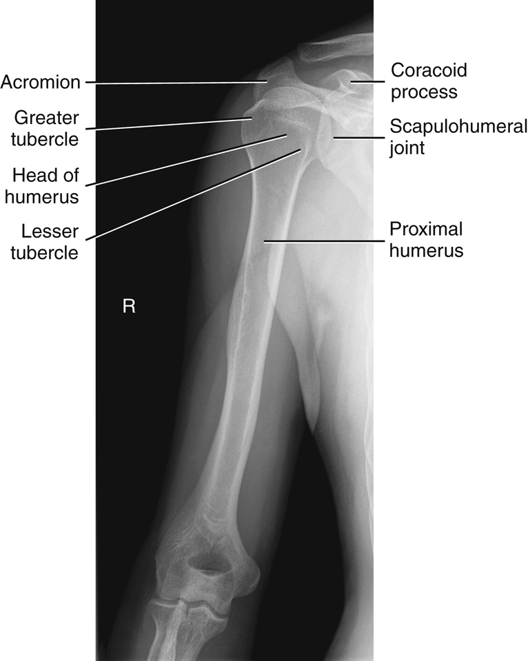
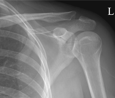
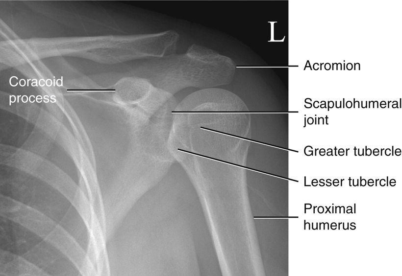
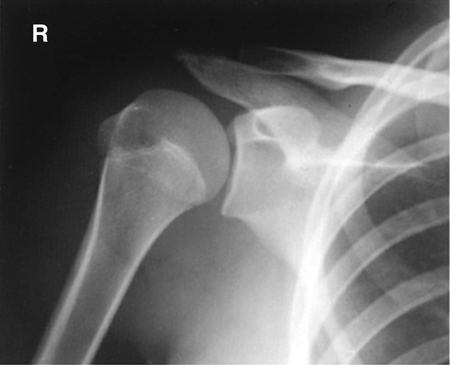
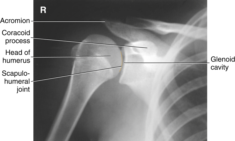
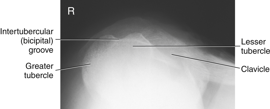
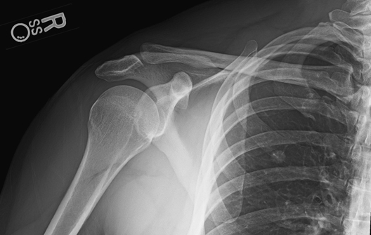
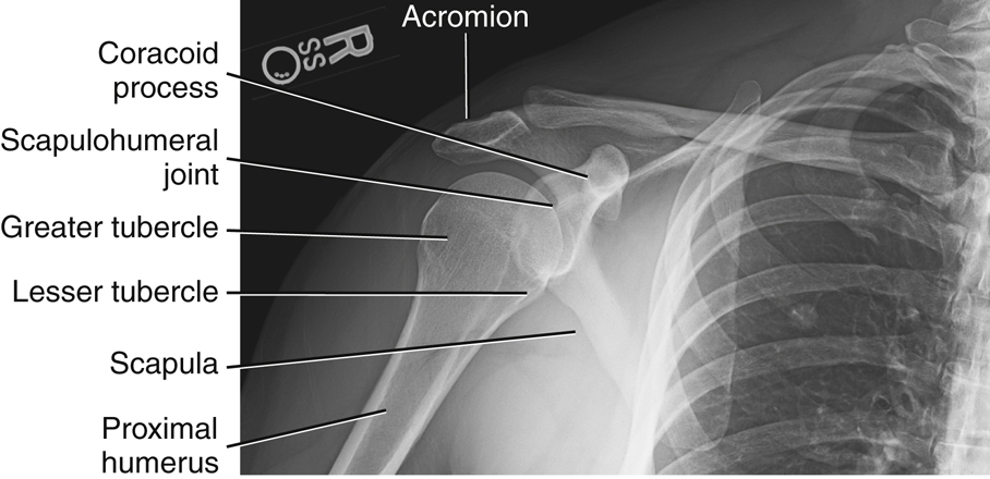
Fig. 5.2 shows a neutral rotation (natural position of the arm without internal or external rotation). This places the humerus in an oblique position midway between an anteroposterior (AP) (external rotation) and a lateral (internal rotation). Fig. 5.3 is an AP radiograph of the shoulder taken with external rotation, which places the humerus in a true AP or frontal position.
Some anatomic parts are more difficult to visualize on radiographs than on drawings. However, a good understanding of the location of various parts and the relationship between them helps in this identification. The following parts are shown in Fig. 5.3:
The relative location of the greater and lesser tubercles is significant in determining a true frontal view or a true AP projection of the proximal humerus. The lesser tubercle is located anteriorly and the greater tubercle is located laterally in a true AP projection.


Shoulder Girdle
The shoulder girdle consists of two bones: the clavicle and the scapula (Fig. 5.4). The function of the clavicle and scapula is to connect each upper limb to the trunk or axial skeleton. Anteriorly, the shoulder girdle connects to the trunk at the upper sternum; however, posteriorly, the connection to the trunk is incomplete because the scapula is connected to the trunk by muscles only.
Each shoulder girdle and each upper limb connect at the shoulder joint between the scapula and the humerus. Each clavicle is located over the upper anterior rib cage. Each scapula is situated over the upper posterior rib cage.
The upper margin of the scapula is at the level of the second posterior rib, and the lower margin is at the level of the seventh posterior rib (T7). The lower margin of the scapula corresponds to T7, also used as a landmark for location of the central ray (CR) for chest positioning (see Chapter 2).
Clavicle
The clavicle (collarbone) is a long bone with a double curvature that has three main parts: two ends and a long central portion. The lateral or acromial (ah-kro′-me-al) extremity (end) of the clavicle articulates with the acromion of the scapula. This joint or articulation is called the acromioclavicular (ah-kro″-me-o-klah-vik′-u-lar) joint and generally can be readily palpated.
The medial or sternal extremity (end) articulates with the manubrium, which is the upper part of the sternum. This articulation is called the sternoclavicular (ster″-no-klah-vik′-u-lar) joint. This joint also is easily palpated, and the combination of the sternoclavicular joints on either side of the manubrium helps to form an important positioning landmark called the jugular (jug′-u-lar) notch.
The body (shaft) of the clavicle is the elongated portion between the two extremities. The acromial end of the clavicle is flattened and has a downward curvature at its attachment with the acromion. The sternal end is more triangular in shape, broader, and is directed downward to articulate with the sternum.
In general, the size and shape of the clavicle differ between males and females. The female clavicle is usually shorter and less curved than the male clavicle. The male clavicle tends to be thicker and more curved, usually being most curved in heavily muscled men.
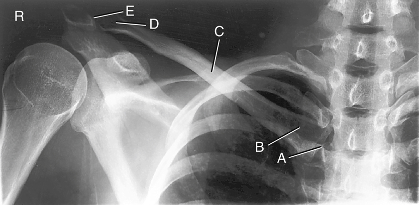
Radiograph of the Clavicle
The AP radiograph of the clavicle in Fig. 5.5 reveals the two joints and the three parts of the clavicle:

Scapula
The scapula (shoulder blade), which forms the posterior part of the shoulder girdle, is a flat triangular bone with three borders, three angles, and two surfaces. The three borders are the medial (vertebral) border, which is the long edge or border near the vertebrae; the superior border, or the uppermost margin of the scapula; and the lateral (axillary) border, or the border nearest the axilla (ak-sil′-ah) (Fig. 5.6). Axilla is the medical term for the armpit.
Anterior View
The three corners of the triangular scapula are called angles (Fig. 5.7). The lateral angle, sometimes called the head of the scapula, is the thickest part and ends laterally in a shallow depression called the glenoid cavity (fossa).
The humeral head articulates with the glenoid cavity of the scapula to form the scapulohumeral (skap″-u-lo-hu′-mer-al) joint, also known as the glenohumeral joint, or shoulder joint.
The constricted area between the head and the body of the scapula is the neck. The superior and inferior angles refer to the upper and lower ends of the medial or vertebral border. The body (blade) of the scapula is arched for greater strength. The thin, flat, lower part of the body sometimes is referred to as the wing or ala of the scapula, although these are not preferred anatomic terms.
The anterior surface of the scapula is termed the costal (kos′-tal) surface because of its proximity to the ribs (costa literally means “rib”). The middle area of the costal surface presents a large concavity or depression, known as the subscapular fossa.
The acromion is a long, curved process that extends laterally over the head of the humerus. The coracoid process is a thick, beaklike process that projects anteriorly beneath the clavicle. The suprascapular notch is a notch on the superior border that is partially formed by the base of the coracoid process.
Posterior View
Fig. 5.8 shows a prominent structure on the dorsal, or posterior, surface of the scapula, called the spine. The elevated spine of the scapula starts at the vertebral border as a smooth triangular area and continues laterally to end at the acromion. The acromion overhangs the shoulder joint posteriorly.
The posterior border or ridge of the spine is thickened and is termed the crest of the spine. The spine separates the posterior surface into an infraspinous (in″-frah-spi′-nus) fossa and a supraspinous fossa. Both fossae serve as surfaces of attachment for shoulder muscles. The names of these muscles are associated with their respective fossae.
Lateral View
The lateral view of the scapula demonstrates relative positions of the various parts of the scapula (Fig. 5.9). The thin scapula looks like the letter Y in this position. The upper parts of the Y are the acromion and the coracoid process. The acromion is the expanded distal end of the spine that extends superiorly and posteriorly to the glenoid cavity (fossa). The coracoid process is located more anteriorly in relationship to the glenoid cavity or shoulder joint.
The lower portion of the Y is the body of the scapula. The posterior surface or back portion of the thin body portion of the scapula is the dorsal surface. The spine extends from the dorsal surface at its upper margin. The anterior surface of the body is the ventral (costal) surface. The lateral (axillary) border is a thicker edge or border that extends from the glenoid cavity to the inferior angle (see Fig. 5.9)


Review Exercise with Radiographs
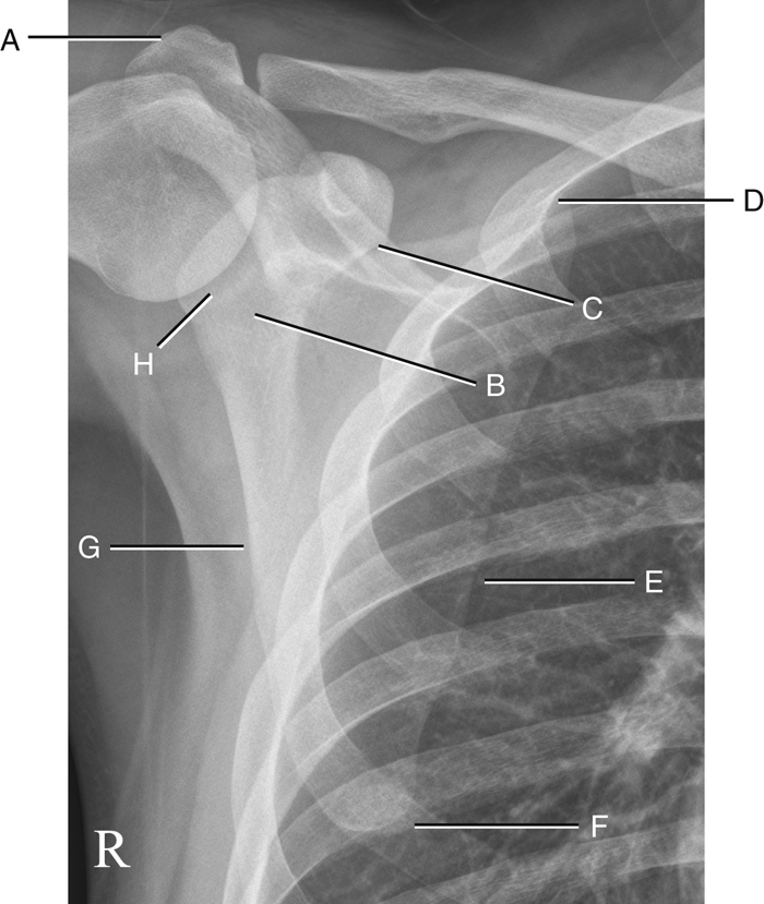
AP Projection
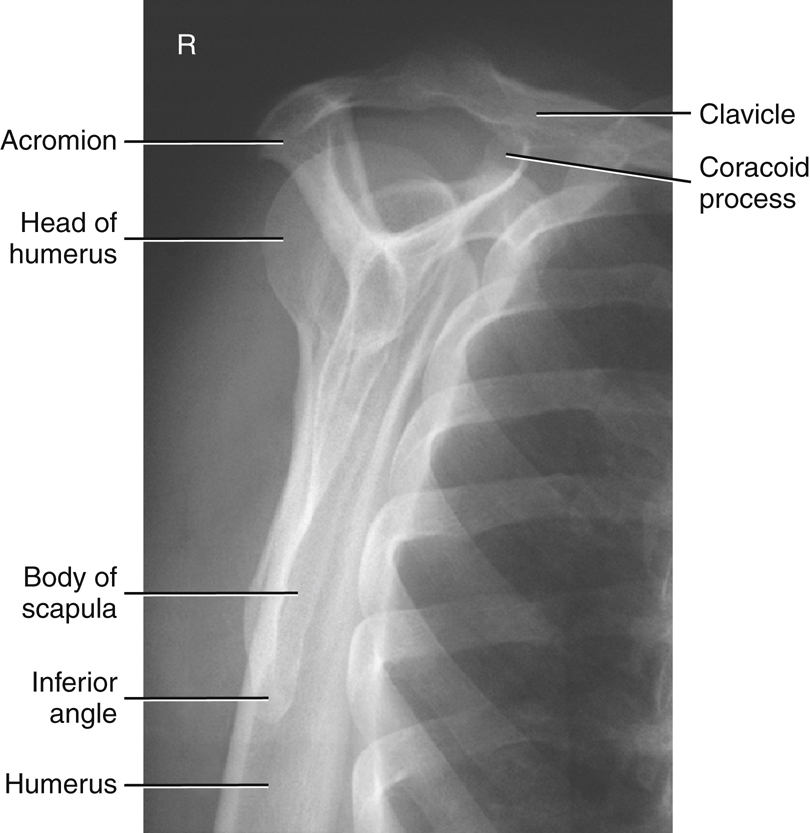
Fig. 5.10 is an AP projection of the scapula taken with the arm abducted so as not to superimpose the scapula. Knowing the shapes and relationships of anatomic parts should help one to identify each of the following parts:
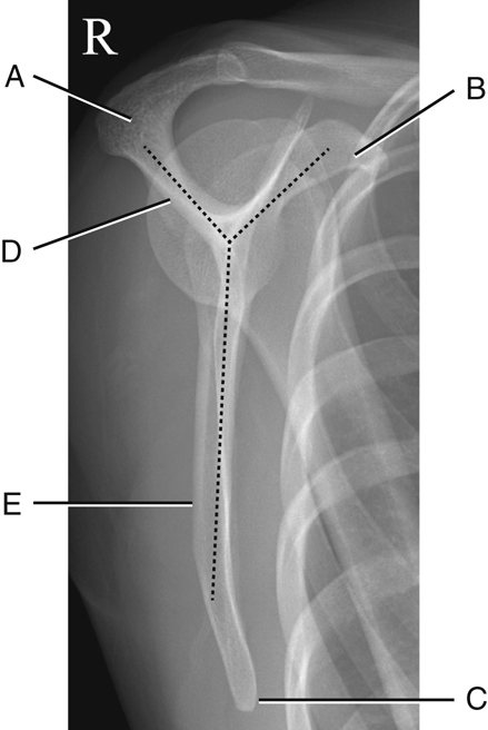
Lateral Projection
In Fig. 5.11 the posteroanterior (PA) oblique–scapular Y lateral projection of the scapula was taken with the patient in an anterior oblique position and with the upper body rotated until the scapula is separated from the rib cage in a true end-on or lateral projection. This lateral view of the scapula presents a Y shape, wherein the acromion and the coracoid process make up the upper legs of the Y, and the body makes up the long lower leg. The scapular Y position gets its name from this Y shape, resulting from a true lateral view of the scapula.
The labeled parts as seen on this view are as follows:
Proximal Humerus and Scapula
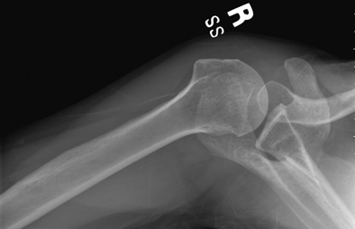
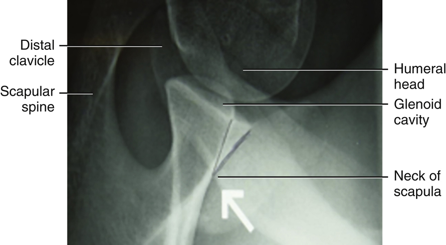
Inferosuperior Axial Projection
This projection (as shown in Fig. 5.12) results in a lateral view of the head and neck of the humerus. It also demonstrates the relationship of the humerus to the glenoid cavity, which makes up the scapulohumeral (glenohumeral) joint.
The anatomy of the scapula may appear confusing in this position, but understanding the relationships between the various parts facilitates identification.
-
- Part A of Fig. 5.13 is the tip of the coracoid process, which is located anterior to the shoulder joint and would be seen superiorly with the patient lying on her back (see Fig. 5.12).
- Part B is the glenoid cavity, which is the articulating surface of the lateral angle or head of the scapula.
- Part C is the spine of the scapula, which is located posteriorly with the patient lying on her back (see Fig. 5.12).
- Part D is the acromion, which is the extended portion of the spine that is superimposed over the humerus in this position.


Classification of Joints
Three joints or articulations are involved in the shoulder girdle: sternoclavicular joint, acromioclavicular joint, and scapulohumeral joint (glenohumeral or shoulder joint) (Fig. 5.14).
Classification
The three shoulder girdle joints (articulations) classified as synovial joints are characterized by a fibrous capsule that contains synovial fluid.
Mobility Type
The mobility type of all three of these joints is freely movable, or diarthrodial. All synovial joints are by nature of their structure freely movable. The only difference between these three joints is their movement type.
Movement Type
The scapulohumeral (glenohumeral) or shoulder joint involves articulation between the head of the humerus and the glenoid cavity of the scapula. The movement type is a ball-and-socket (spheroidal) joint, which allows great freedom of movement. These movements include flexion, extension, abduction, adduction, circumduction, and medial (internal) and lateral (external) rotation.
The glenoid cavity is very shallow, allowing the greatest freedom in mobility of any joint in the human body but at some expense to its strength and stability. Strong ligaments, tendons, and muscles surround the joint, providing stability. However, stretching of the muscles and tendons can cause separation or dislocation of the humeral head from the glenoid cavity. Dislocations at the shoulder joint occur more frequently than at any other joint in the body, creating the need for frequent radiographic examinations of the shoulder to evaluate for structural damage. The shoulder girdle also includes two joints involving both ends of the clavicle, called the sternoclavicular and acromioclavicular joints.
The sternoclavicular joint is a double plane, or gliding, joint because the sternal end of the clavicle articulates with the manubrium or upper portion of the sternum and the cartilage of the first rib. A limited amount of gliding motion occurs in nearly every direction.
The acromioclavicular joint is also a small synovial joint of the plane, or gliding,
movement
type between the acromial end of the clavicle and the medial aspect of the acromion of the scapula. Two types of movement occur at this joint. The primary movement is a gliding action between the end of the clavicle and the acromion. Some secondary rotary movement also occurs as the scapula moves forward and backward with the clavicle. This movement allows the scapula to adjust its position as it remains in close contact with the posterior chest wall. However, the rotary type of movement is limited, and this joint generally is referred to as a plane, or gliding-type, joint. Table 5.1 presents a summary of the shoulder girdle joints.

TABLE 5.1

Radiographic Positioning
Proximal Humerus Rotation
Radiographs of the Proximal Humerus
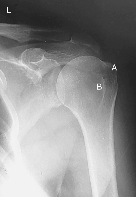
Rotational views of the proximal humerus or shoulder girdle are commonly taken on nontrauma patients when gross fractures or dislocations of the humerus have been ruled out. These AP rotational projections delineate well the scapulohumeral joint (shoulder joint), revealing possible calcium deposits or other pathology. Note specifically the location and shapes of the greater tubercle (A) and the lesser tubercle (B) on these external, internal, and neutral rotation radiographs (Figs. 5.16, 5.18, and 5.20).
By studying the position and relationships of the greater and lesser tubercles on a radiograph of the shoulder, you can determine the rotational position of the arm. This understanding enables you to know which rotational view is necessary for visualization of specific parts of the proximal humerus.
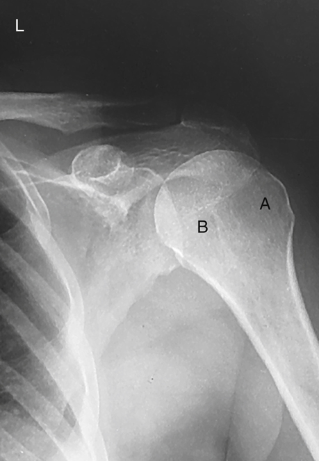
External Rotation
The external rotation position represents a true AP projection of the humerus in the anatomic position, as determined by the epicondyles of the distal humerus. Positioning requires supination of the hand and external rotation of the elbow so that the interepicondylar line is parallel to the image receptor (IR) (Fig. 5.15).
NOTE: You can check this on yourself by dropping your arm at your side and externally rotating your hand and arm while palpating the epicondyles of your distal humerus.
On the external rotation radiograph (see Fig. 5.16), the greater tubercle (A), which is located anteriorly in a neutral position, is now seen laterally in profile. The lesser tubercle (B) now is located anteriorly, just medial to the greater tubercle.
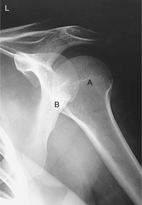
Internal Rotation
For the internal rotation position, the hand and arm are rotated internally until the epicondyles of the distal humerus are perpendicular to the IR, placing the humerus in a true lateral position. The hand must be pronated and the elbow adjusted to place the epicondyles perpendicular to the IR (Fig. 5.17).
The AP projection of the shoulder taken in the internal rotation position (see Fig. 5.18) is a lateral position of the proximal humerus in which the greater tubercle (A) now is rotated around to the anterior and medial aspect of the proximal humerus. The lesser tubercle (B) is seen in profile medially.
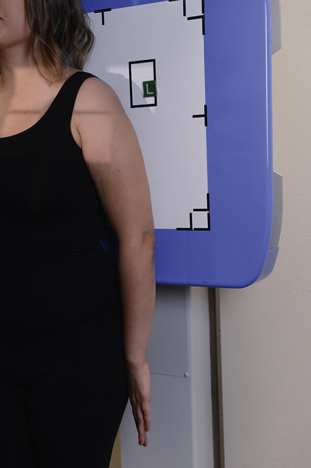
Neutral Rotation
Neutral rotation is appropriate for a trauma patient when rotation of the part is unacceptable. The epicondyles of the distal humerus appear at an approximate 45° angle to the IR (Fig. 5.19). A 45° oblique position of the humerus results when the palm of the hand is facing inward toward the thigh. The neutral position is approximately midway between the external and internal positions and places the greater tubercle anteriorly but still lateral to the lesser tubercle, as can be seen on the radiograph in Fig. 5.20.


Positioning and Exposure Considerations
General positioning considerations for the humerus and shoulder girdle (clavicle and scapula) are similar to those for other upper and lower limb procedures.
Technical Considerations
Depending on part thickness, the humerus can be exposed with or without a grid. Grids generally are used when the humerus projection is performed erect with the use of a Bucky. However, adult shoulders generally measure 10 to 15 cm, and the use of a grid is required. Other technical considerations are listed subsequently. Children and thin, asthenic adults may measure less than 10 cm, requiring exposure factor adjustments without the use of grids. Acromioclavicular (AC) joints generally also measure less than 10 cm and require less kVp (70 to 75) without grids. However, this practice can vary, depending on department protocol, and grids are often used for AC joints to reduce scatter radiation. But the use of a grid results in added dose to the patient caused by the required increase in exposure factors.
Average Adult Humerus and Shoulder
- 1. Medium kVp, 70 to 85, with grid for shoulder thickness >10 cm (<10 cm, 70 to 75 kVp without grid)
- 2. Higher milliampere (mA) with short exposure times
- 3. Small focal spot
- 4. Center cell for automatic exposure control (AEC) if used for the shoulder (manual techniques may be recommended with certain projections, such as humerus and AC joints)
- 5. Adequate mAs for sufficient density (brightness) (for visualization of soft tissues, bone margins, and trabecular markings of all bones)
- 6. 40- to 44-inch (100- to 110-cm) source–image receptor distance (SID) except for AC joints, which may use a 72-inch (180-cm) SID for less beam divergence. This is highly effective in demonstrating comparative studies of the AC joints with both joints in a single exposure.
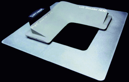
- 7. Compensating filter: The use of a boomerang filter for AP projections of the shoulder and scapula permits both soft tissues and bony anatomy to be demonstrated clearly. It is especially effective in demonstrating the acromion and AC joint region while allowing for optimal visualization of the denser shoulder joint region (Figs. 5.21 and 5.22).
Radiation Protection
Gonadal Shielding
Generally, gonadal shielding is important for upper limb radiography because of the proximity of parts of the upper limb, such as the hands or wrists, to the gonads when radiography is performed with the patient in a supine position. The relationship of the divergent x-ray beam to the pelvic region when a patient is in an erect seated position also necessitates gonadal protection. Protecting radiosensitive regions of the body whenever possible for procedures is good practice and reassures the patient.
Shielding of Thyroid, Lungs, and Breasts
Radiography of the shoulder region may deliver potentially significant doses to the thyroid, lung regions, and to the breasts, all of which are radiosensitive organs. Close collimation to the area of interest is important, as is providing contact shields over portions of the lungs, breast, and thyroid regions that do not obscure the area of interest.

Special Patient Considerations
Pediatric Applications
The routines used for radiographic examinations of the humerus and shoulder girdle generally do not vary significantly from adult to pediatric patients, although it is essential that exposure technique be decreased to compensate for the decrease in tissue quantity and density (brightness). Patient motion plays an important role in pediatric radiography. Immobilization often is necessary to assist the child in maintaining the proper position. Sponges and tape are very useful, but caution is necessary when sandbags are used because of the weight of the sandbags.
Parents frequently are asked to assist with the radiographic examination of their child. If parents are permitted in the radiography room during the exposure, proper shielding must be provided. To ensure maximum cooperation, the technologist should speak to the child in a soothing manner and should use words that the child can easily understand.
Geriatric Applications
It is essential to provide clear and complete instructions to an older patient. Routine humerus and shoulder girdle examinations may have to be altered to accommodate the physical condition of an older patient. Reduction in radiographic technique may be necessary as a result of destructive pathologies commonly seen in geriatric patients.
Bariatric Patient Considerations
With bariatric patients, alternative palpation points (the jugular notch and AC joint) should be used for shoulder projections instead of the coracoid process. If you choose to use the AC joint to identify the shoulder joint, go 2 inches (5 cm) inferior to the AC joint and ½ inch (1.25 cm) medial to locate the scapulohumeral joint.
Use a boomerang compensating filter for AP projections of the shoulder and scapula because of the increased shoulder thickness. This permits greater visibility of both soft tissue and bony anatomy. Perform positions erect when possible for patient comfort and to reduce object–image receptor distance (OID) and part distortion as a result of curved shoulders. Collimation is critical to reduce scatter reaching the image receptor. The proximal humerus should be performed with a grid. Although it will add to the patient dose, it will reduce scatter radiation and increase image contrast and visibility of the anatomy.
Digital Imaging Considerations
Specific guidelines should be followed when digital imaging systems are used for imaging the humerus and shoulder girdle. These guidelines were described in greater detail in Chapter 4 for the upper limb and are summarized here:
- 1. Collimation: Close collimation is important for ensuring that the final image after processing is of optimal quality.
- 2. Accurate centering: Because of the way the digital image plate reader scans the exposed imaging plate, it is important that the body part and the CR be accurately centered to the IR.
- 3. Exposure factors: With regard to patient exposure, the ALARA principle (as low as reasonably achievable) must be followed: the lowest exposure factors required to obtain a diagnostic image should be used. This involves using the highest kVp and the lowest mAs that result in a final image of diagnostic quality.
- 4. Post-processing evaluation of exposure indicator: After the image has been processed and is ready for viewing, the technologist must assess the exposure indicator to verify that the exposure factors used met ALARA standards and produced a quality image.
Alternative Modalities and Procedures
Arthrography
Arthrography sometimes is used to image soft tissue pathologies such as rotator cuff tears associated with the shoulder girdle. This procedure, which is described in greater detail in Chapter 19, requires the use of a radiographic contrast medium injected into the joint capsule under fluoroscopy and sterile conditions.
Computed Tomography (CT) and Magnetic Resonance Imaging (MRI)
CT and MRI often are used on the shoulder to evaluate soft tissue and skeletal involvement of lesions and soft tissue injuries. Sectional CT images also are excellent for determining the extent of fracture. MRI, with or without the use of a contrast agent, is useful in the diagnosis of rotator cuff injuries. CT arthrography, as described in Chapter 18, can be performed instead of or in conjunction with conventional arthrography.
Nuclear Medicine (NM)
Nuclear medicine bone scans are useful in demonstrating osteomyelitis, metastatic bone lesions, and cellulitis. Nuclear medicine scans demonstrate pathology within 24 hours of onset. Nuclear medicine is more sensitive than radiography because it assesses the physiologic aspect instead of the anatomic aspect.
Sonography
Ultrasound is useful for musculoskeletal imaging of joints such as the shoulder to evaluate soft tissues within the joint for possible rotator cuff tears; bursa injuries; or disruption and damage to nerves, tendons, or ligaments. These studies can be used as an adjunct to more expensive MRI studies. Ultrasound also allows for dynamic evaluation during joint movement.
Clinical Indications
Clinical indications involving the shoulder girdle with which all technologists should be familiar include the following conditions.
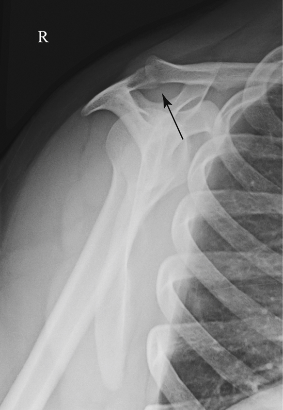
- AC joint separation refers to trauma to the upper shoulder region resulting in a partial or complete tear of the AC or coracoclavicular (CC) ligament or both ligaments. AC joint injuries represent nearly half of all athletic shoulder injuries, often resulting from a fall onto the tip of the shoulder with the arm in adduction. Currently there are six classifications of AC joint separation, ranging from a sprain to a complete separation of the distal clavicle from acromion as a result of ligament tears. 1
- Acromioclavicular dislocation refers to an injury in which the distal clavicle usually is displaced superiorly. This injury most commonly is caused by a fall and is more common in children than adults. 2
- Bankart lesion is an injury of the anteroinferior aspect of the glenoid labrum. This type of injury often is caused by anterior dislocation of the proximal humerus. Repeated dislocation may result in a small avulsion fracture in the anteroinferior region of the glenoid rim.
- Bursitis (ber-sy′-tis) is an inflammation of the bursae, or fluid-filled sacs enclosing the joints. The shoulder is the most common joint to develop bursitis, with repetitive motion being the most common cause. However, trauma, rheumatoid arthritis, and infection can also produce bursitis. 3 It generally involves the formation of calcification in associated tendons, causing pain and limitation of joint movement.
- Hill-Sachs defect is a compression fracture of the articular surface of the posterolateral aspect of the humeral head that often is associated with an anterior dislocation of the humeral head.
- Idiopathic chronic adhesive capsulitis (frozen shoulder) is a disability of the shoulder joint that is caused by chronic inflammation in and around the joint. It is characterized by pain and limitation of motion. (Idiopathic means of unknown cause.)
- Impingement syndrome is impingement of the greater tuberosity and soft tissues on the coracoacromial ligamentous and osseous arch, generally during abduction of the arm. 4
- Osteoarthritis, also called degenerative joint disease (DJD), is a noninflammatory joint disease characterized by gradual deterioration of the articular cartilage with hypertrophic bone formation. DJD is the most common type of arthritis and is considered part of the normal aging process. It generally occurs in persons older than 50 years, chronically bariatric persons, and athletes.
- Osteoporosis (os″-te-o-po-ro′-sis) and resultant fractures are to the result of a reduction in the quantity of bone or atrophy of skeletal tissue. Osteoporosis occurs in postmenopausal women and elderly men, resulting in bony trabeculae that are scanty and thin. Most fractures sustained by women older than 50 years are related to osteoporosis.
- Rheumatoid (ru′-ma-toyd) arthritis (RA) is a chronic systemic disease characterized by inflammatory changes that occur throughout the connective tissues of the body. The inflammation begins in synovial membranes and can later involve the articular cartilage and bony cortex. RA occurs more frequently in women than men. Radiographic evidence of RA includes loss of joint space, destruction cortical bone and bony deformity. 1
- Rotator cuff pathology is an acute or a chronic traumatic injury to one or more of the rotator cuff muscles: teres minor, supraspinatus, infraspinatus, and subscapularis. Rotator cuff injuries limit the range of motion of the shoulder. The most common injury of the rotator cuff is impingement of the supraspinatus tendon as it passes beneath the acromion, caused by a subacromial bone spur. Repeated irritation associated with the bone spur can lead to a partial or complete tear of the supraspinatus tendon, as evident on MRI and sonographic examination of the shoulder (Figs. 5.23 and 5.24).
- Shoulder dislocation is traumatic removal of the humeral head from the glenoid cavity. Of shoulder dislocations, 95% are anterior, in which the humeral head is projected anterior to the glenoid cavity.
- Tendonitis (ten″-de-ni′-tis) is an inflammatory condition of the tendon that usually results from a strain.
Table 5.2 presents a summary of clinical indications.
Routine, Alternate, and Special Projections
Routine, alternate, and special projections of the humerus, shoulder, clavicle, AC joints, and scapula are demonstrated and described on the following pages.

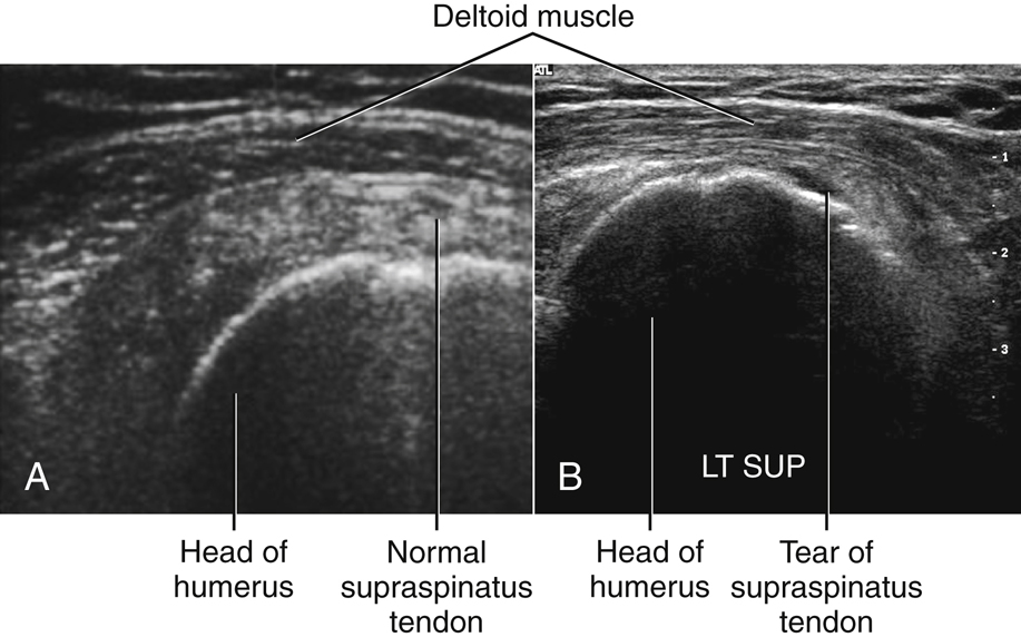
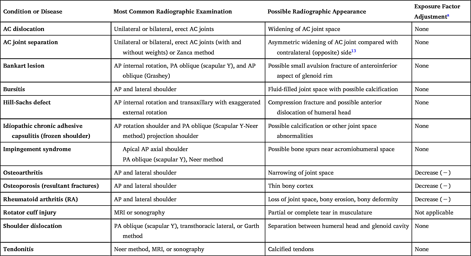
TABLE 5.2
| Condition or Disease | Most Common Radiographic Examination | Possible Radiographic Appearance | Exposure Factor Adjustment a |
|---|---|---|---|
| AC dislocation | Unilateral or bilateral, erect AC joints | Widening of AC joint space | None |
| AC joint separation | Unilateral or bilateral, erect AC joints (with and without weights) or Zanca method | Asymmetric widening of AC joint compared with contralateral (opposite) side 13 | None |
| Bankart lesion | AP internal rotation, PA oblique (scapular Y), and AP oblique (Grashey) | Possible small avulsion fracture of anteroinferior aspect of glenoid rim | None |
| Bursitis | AP and lateral shoulder | Fluid-filled joint space with possible calcification | None |
| Hill-Sachs defect | AP internal rotation and transaxillary with exaggerated external rotation | Compression fracture and possible anterior dislocation of humeral head | None |
| Idiopathic chronic adhesive capsulitis (frozen shoulder) | AP rotation shoulder and PA oblique (Scapular Y-Neer method) projection shoulder | Possible calcification or other joint space abnormalities | None |
| Impingement syndrome |
Apical AP axial shoulder
PA oblique (scapular Y), Neer method
|
Possible bone spurs near acromiohumeral space | None |
| Osteoarthritis | AP and lateral shoulder | Narrowing of joint space | Decrease (−) |
| Osteoporosis (resultant fractures) | AP and lateral shoulder | Thin bony cortex | Decrease (−) |
| Rheumatoid arthritis (RA) | AP and lateral shoulder | Loss of joint space, bony erosion, bony deformity | Decrease (−) |
| Rotator cuff injury | MRI or sonography | Partial or complete tear in musculature | Not applicable |
| Shoulder dislocation | PA oblique (scapular Y), transthoracic lateral, or Garth method | Separation between humeral head and glenoid cavity | None |
| Tendonitis | Neer method, MRI, or sonography | Calcified tendons | None |
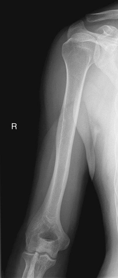
AP Projection: Humerus
WARNING: Do not attempt to rotate the arm if a fracture or dislocation is suspected.
Clinical Indications
Technical Factors
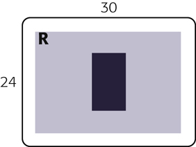
- • Minimum SID—40 inches (100 cm)
- • IR size–portrait (large enough to include entire humerus)
- • 14 × 17 inches (35 × 43 cm) may be needed to place cassette diagonally to include both joints
- • For pediatric patient, 10 × 12 inches (24 × 30 cm)
- • Grid (nongrid for humerus <10 cm thickness)
- • kVp range: 70–85

Shielding
Shield radiosensitive tissues outside region of interest.
Patient Position
Part Position

- • Rotate body toward affected side as needed to bring shoulder and proximal humerus into contact with cassette.
- • Align humerus with long axis of IR, unless diagonal placement is needed to include both shoulder and elbow joints.
- • Extend hand and forearm as far as patient can tolerate.
- • Abduct arm slightly and gently supinate hand so that epicondyles of elbow are parallel and equidistant from IR.
CR
Recommended Collimation
Collimate on sides to soft tissue borders of humerus and shoulder. (Lower margin of collimation field should include the elbow joint and approximately 1 inch (2.5 cm) minimum of proximal forearm.)
Respiration
Suspend respiration during exposure.


Rotational Lateral—Lateromedial orMediolateral Projections: Humerus
WARNING: Do not attempt to rotate the arm if a fracture or dislocation is suspected (see Trauma Horizontal Beam Lateral, p. 189).
Clinical Indications
Technical Factors

Shielding
Shield radiosensitive tissues outside region of interest.
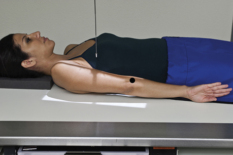
Patient and Part Position
- • Position patient erect or supine as for lateromedial or mediolateral projection.
- • Lateromedial: Position patient erect with back to IR and elbow partially flexed, with body rotated toward affected side as needed to bring humerus and shoulder in contact with cassette. Internally rotate arm as needed for lateral position; epicondyles are perpendicular to IR (Figs. 5.29 and 5.30).
- • Mediolateral: Face patient toward IR (Fig. 5.31) and oblique as needed (20° to 30° from PA) to allow close contact of humerus with IR; flex elbow 90° as shown.
- • Adjust image receptor height so that shoulders and elbow joints are equidistant from ends of it.
CR
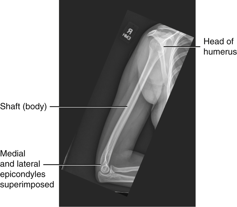
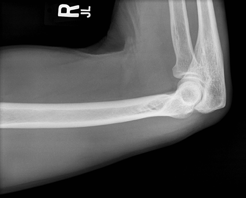
Recommended Collimation
Collimate on four sides to soft tissue border of humerus, ensuring that all of shoulder and elbow joints are included (Fig. 5.32).
Respiration
Suspend respiration during exposure.


Trauma Horizontal Beam Lateral—Lateromedial Projection:Mid-To-Distal Humerus
Distal Humerus
WARNING: Do not attempt to rotate the arm if a fracture or dislocation is suspected.
This projection is used in conjunction with the Transthoracic Lateral, p. 14.
Clinical Indications
Technical Factors

Shielding
Shield radiosensitive tissues outside region of interest.
Patient and Part Position
- • With patient recumbent, perform image as a horizontal beam lateral, placing support under the arm (Fig. 5.34).
- • Flex elbow if possible, but do not attempt to rotate arm; projection should be 90° from AP.
- • Gently place image receptor between arm and thorax (top of IR to axilla).
CR
Recommended Collimation
Collimate to soft tissue margins. Include distal humerus and midhumerus, elbow joint, and proximal forearm.
Respiration
Suspend respiration during exposure. (This step is important in preventing movement of the image receptor during the exposure.)


Transthoracic Lateral Projection: Humerus (Trauma)
Clinical Indications
Technical Factors

Shielding
Shield radiosensitive tissues outside region of interest.
Patient Position
Place patient in an erect or a supine position. (The erect position, which may be more comfortable for the patient, is preferred.) Place patient in lateral position with side of interest closest to IR (Fig. 5.37). With patient supine, place portable grid lines horizontally and center CR to centerline to prevent grid cutoff (Fig. 5.37, inset).
Part Position
- • Place affected arm at patient’s side in neutral rotation; drop shoulder if possible.
- • Raise opposite arm and place hand over top of head; elevate shoulder as much as possible to prevent superimposition of affected shoulder.
- • Center mid-diaphysis of affected humerus and center of IR to CR as projected through thorax.
- • Ensure that thorax is in a true lateral position or has slight anterior rotation of unaffected shoulder to minimize superimposition of humerus by thoracic vertebrae.
CR
Recommended Collimation
Collimate on four sides to area of interest.
Respiration
Orthostatic (breathing) technique is preferred if patient can cooperate. Patient should be asked to breathe gently in short, shallow breaths without moving affected arm or shoulder. (This allows best visualization of humerus by blurring out ribs and lung structures.)
NOTE: If patient is in too much pain to drop injured shoulder and elevate uninjured arm and shoulder high enough to prevent superimposition of shoulders, angle CR 10° to 15° cephalad.


AP Projection—External Rotation: Shoulder (Nontrauma)
AP Proximal Humerus
WARNING: Do not attempt to rotate the arm if a fracture or dislocation is suspected (see preceding trauma routine).
Clinical Indications
Technical Factors

Shielding
Shield radiosensitive tissues outside region of interest.
Patient Position
Perform radiograph with patient in an erect or a supine position. (The erect position is usually less painful for patient, if condition allows.) Rotate body slightly toward affected side if necessary to place shoulder in contact with IR or tabletop (Fig. 5.40).
Part Position
CR
Recommended Collimation
Collimate on four sides, with lateral and upper borders adjusted to soft tissue margins.
Respiration
Suspend respiration during exposure.
NOTE: The coracoid process may be difficult to palpate directly on most patients, but it can be approximated; it is approximately 2 inches (5 cm) inferior to the lateral portion of the more readily palpated AC joint.


AP Projection—Internal Rotation: Shoulder (Nontrauma)
Lateral Proximal Humerus
WARNING: Do not attempt to rotate the arm if a fracture or dislocation is suspected (see trauma projections, p. 200–203).
Clinical Indications
Technical Factors

Shielding
Shield radiosensitive tissues outside region of interest.
Patient Position
Perform radiograph with patient in an erect or supine position. (The erect position is usually less painful for patient, if condition allows.) Rotate body slightly toward affected side, if necessary, to place shoulder in contact with IR or tabletop (Fig. 5.43).
Part Position
CR
Recommended Collimation
Collimate on four sides, with lateral and upper borders adjusted to soft tissue margins.
Respiration
Suspend respiration during exposure.

Inferosuperior Axial Projection: Shoulder (Nontrauma)
Lawrence Method 5
WARNING: Do not attempt to rotate the arm or force abduction if a fracture or dislocation is suspected.
Clinical Indications
Technical Factors

Shielding
Shield radiosensitive tissues outside region of interest.
Patient Position
Position patient supine with shoulder raised approximately 2 inches (5 cm) from tabletop by placing support under arm and shoulder to place body part near center of IR (Fig. 5.46).
Part Position
- • Move patient toward the front edge of tabletop and place a cart or other arm support against front edge of table to support abducted arm.
- • Rotate head toward opposite side, place vertical cassette on table as close to neck as possible, and support with sandbags.
- • Abduct arm 90° from body if possible; keep in external rotation, palm up, with support under arm and hand.
CR
Recommended Collimation
Collimate closely on four sides.
Respiration
Suspend respiration during exposure.
An alternative position is exaggerated external rotation
4
(Fig. 5.47). Anterior dislocation of the humeral head may result in a compression fracture of the articular surface of the humeral head, called the Hills-Sachs defect. This pathology is best demonstrated by exaggerated external rotation, wherein the thumb is pointed down and posteriorly approximately 45°.


PA Axial Transaxillary Projection: Shoulder (Nontrauma)
Modified Bernageau Method
WARNING: Do not attempt to rotate, force extension, or abduct the arm if a fracture or dislocation is suspected.
Clinical Indications
Technical Factors

Shielding
Shield radiosensitive tissues outside region of interest.
Patient Position
Part Position
- • The arm is raised superiorly to 160° to 180° flexion. 6
- • The head is turned away from the affected arm.
CR
- • CR is directed 30° caudally and centered at the level of the scapular spine to pass through the scapulohumeral joint. 6
Recommended Collimation
Collimate closely on four sides.
Respiration
Suspend respiration during exposure.

Inferosuperior Axial Projection: Shoulder (Nontrauma)
Clements Modification 7
WARNING: Do not attempt to rotate the arm or force abduction if a fracture or dislocation is suspected.
Clinical Indications
Technical Factors

Shielding
Shield radiosensitive tissues outside region of interest.
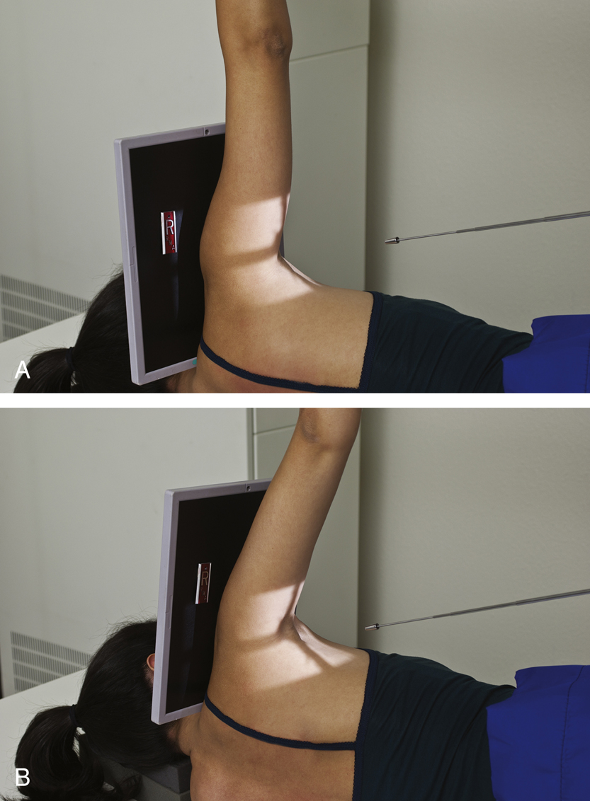
Patient Position
Place patient in the lateral recumbent position with the affected arm up.
Part Position
- • Abduct arm 90° from body if possible (Fig. 5.53A).
CR
- • Direct horizontal CR perpendicular to IR.
- • If patient cannot abduct the arm 90°, angle the tube 5° to 15° toward the axilla (Fig. 5.53B).
Recommended Collimation
Collimate closely on four sides.
Respiration
Suspend respiration during exposure.
AP Oblique Projection—Glenoid Cavity: Shoulder (Nontrauma)
Grashey Method
Clinical Indications
Technical Factors

Shielding
Shield radiosensitive tissues outside region of interest.
Patient Position
Perform radiograph with patient in an erect or a supine position. (The erect position is usually less painful for patient, if condition allows.)
Part Position
- • Rotate body 35° to 45° toward affected side (see NOTE) (Fig. 5.55). If the position is performed with the patient in the recumbent position, place supports under elevated shoulder and hip to maintain this position.
- • Center mid-scapulohumeral joint to CR and to center of IR.
- • Adjust image receptor so that top of IR is approximately 2 inches (5 cm) above shoulder and side of IR is approximately 2 inches (5 cm) from lateral border of humerus (Fig. 5.56).
- • Abduct arm slightly with arm flexed and in neutral rotation.
CR
Recommended Collimation
Collimate so that upper and lateral borders of the field are to the soft tissue margins.
Respiration
Suspend respiration during exposure.
NOTE: Degree of rotation varies, depending on how flat or round the patient’s shoulders are or if position is performed recumbent rather than erect. Having a rounded or curved shoulder or using the recumbent position requires more rotation to place the body of the scapula parallel to the IR.

Apical AP Axial Projection: Shoulder 8
Clinical Indications
Technical Factors

Shielding
Shield radiosensitive tissues outside region of interest.
Patient Position
Perform radiograph with patient in an erect or a recumbent position. (The erect position is usually less painful for patient, if condition allows.)
Part Position
- • Position patient into AP, erect position with no rotation.
- • Extend and slightly abduct arm and hand is placed into neutral rotation.
- • Adjust image receptor so that top of IR is approximately 1 inch (2.5 cm) above shoulder and side of IR is approximately 2 inches (5 cm) from lateral border of humerus (Fig. 5.59).
CR
Recommended Collimation
Collimate so that upper and lateral borders of the field are to the soft tissue margins.
Respiration
Suspend respiration during exposure.

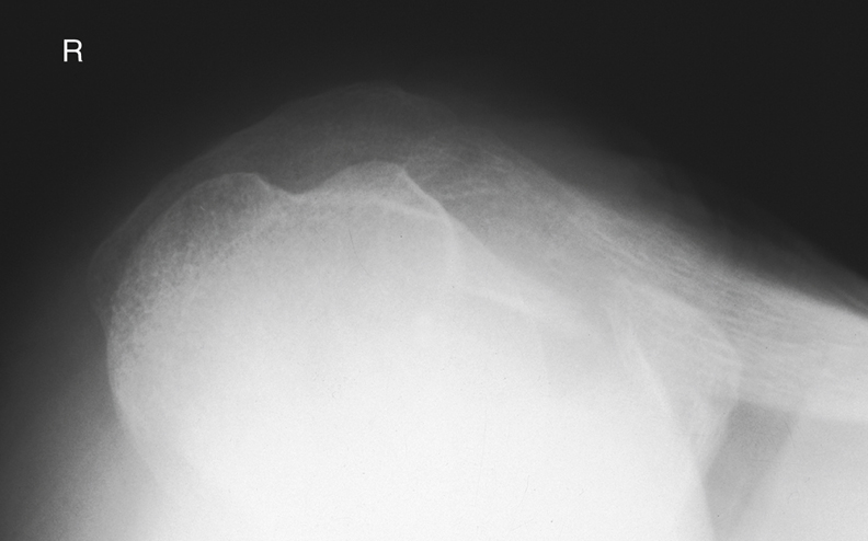
Tangential Projection—Intertubercular (Bicipital) Sulcus: Shoulder (Nontrauma)
Fisk Modification
Clinical Indications
Technical Factors
Shielding
Shield radiosensitive tissues outside region of interest.
Patient and Part Position
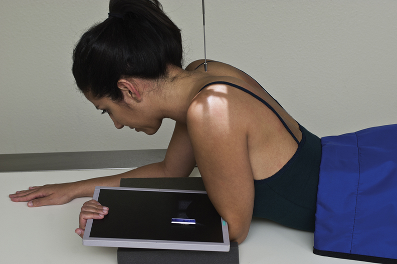
Erect (Fisk Modification)
- • Patient standing, leaning over end of table with elbow flexed and posterior surface of forearm resting on table, hand supinated holding image receptor, head turned away from affected side (lead shield placed between back of IR and forearm reduces backscatter to IR) (Fig. 5.62)
- • Patient leaning forward slightly to place humerus 10° to 15° from vertical
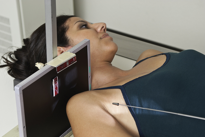
Supine
- • Patient supine, arm at side, hand supinated
- • Vertical image receptor placed on table against top of shoulder and against neck (head turned away from affected side) (Fig. 5.63)
- • CR 10° to 15° posterior from horizontal, directed to groove at midanterior margin of humeral head
CR
Recommended Collimation
Collimate closely on four sides to area of anterior humeral head.
Respiration
Suspend respiration during exposure.
AP Projection—Neutral Rotation: Shoulder (Trauma)
WARNING: Do not attempt to rotate the arm if a fracture or dislocation is suspected; perform in neutral rotation, which generally places humerus in an oblique position.
Clinical Indications
Technical Factors

Shielding
Shield radiosensitive tissues outside region of interest.
Patient Position
Part Position
CR
Recommended Collimation
Collimate on four sides, with lateral and upper borders adjusted to soft tissue margins.
Respiration
Suspend respiration during exposure.


Transthoracic Lateral Projection: Proximal Humerus (Trauma)
Lawrence Method
Clinical Indications
Technical Factors
- • Minimum SID—40 inches (100 cm)
- • IR size—10 × 12 inches (24 × 30 cm), portrait
- • Grid, vertical, CR to centerline
- • kVp range: 70–80
- • Minimum of 3 seconds exposure time with orthostatic (breathing) technique (4 or 5 seconds is desirable). This technique will blur the surrounding pulmonary structures while keeping the proximal humerus in a relatively stationary position.

Shielding
Shield radiosensitive tissues outside region of interest.
Patient Position
Perform radiograph with patient in erect or supine position. (The erect position is preferred and may be more comfortable for patient.) Place patient in lateral position with side of interest against IR. With patient supine, place grid lines vertically and center CR to centerline to prevent grid cutoff (Figs. 5.70 and 5.71).
Part Position
- • Place affected arm at patient’s side in neutral rotation; drop shoulder if possible.
- • Raise opposite arm and place hand over top of head; elevate shoulder as much as possible to prevent superimposition of affected shoulder.
- • Center surgical neck and center of IR to CR as projected through thorax.
- • Ensure that thorax is in a true lateral position or has slight anterior rotation of unaffected shoulder to minimize superimposition of humerus by thoracic vertebrae.
CR
Recommended Collimation
Collimate on four sides to area of interest.
Respiration
Expose on full inspiration. Orthostatic (breathing) technique is preferred if patient can cooperate. Patient should be asked to breathe gently short, shallow breaths without moving affected arm or shoulder. (This best visualizes proximal humerus by blurring out ribs and lung structures.)
NOTE: If patient is in too much pain to drop injured shoulder and elevate uninjured arm and shoulder fully to prevent superimposition of shoulders, angle CR 10° to 15° cephalad.


PA Oblique Projection—Scapular Y Lateral: Shoulder (Trauma)
WARNING: Do not attempt to rotate the arm if a fracture or dislocation is suspected.
Clinical Indications
Technical Factors

Shielding
Shield radiosensitive tissues outside region of interest.
Patient Position
Perform radiograph with patient in erect or recumbent position. (The erect position is usually more comfortable for the patient.)
Part Position
- • Rotate into an anterior oblique position as for a lateral scapula with patient facing IR. Palpate the superior angle of the scapula and AC joint articulation. Rotate the patient until an imaginary line between those two points is perpendicular to IR. Because of differences among patients, the amount of body obliquity may range from 45° to 60° (Fig. 5.74). Center scapulohumeral joint to CR and to center of IR.
- • Abduct arm slightly if possible so as not to superimpose proximal humerus over ribs; do not attempt to rotate arm.
CR
Recommended Collimation
Collimate on four sides to area of interest.
Respiration
Suspend respiration during exposure.
NOTE: If necessary, because of the patient’s condition, this PA oblique (scapular Y lateral) may be taken recumbent in the opposite AP oblique position with injured shoulder elevated (see Lateral Scapula, Recumbent).


Tangential Projection—Supraspinatus Outlet: Shoulder (Trauma)
Neer Method 9
WARNING: Do not attempt to rotate the arm if a fracture or dislocation is suspected.
Clinical Indications
- • Fractures or dislocations of proximal humerus and scapula
- • Specifically demonstrates coracoacromial arch for supraspinatus outlet region for possible shoulder impingement 10

Technical Factors

Shielding
Shield radiosensitive tissues outside region of interest.
Patient Position
Take radiograph with patient in erect or recumbent position. (The erect position is usually more comfortable for patient.)
Part Position
- • With patient facing IR, rotate into anterior oblique position as for a lateral scapula.
- • Palpate superior angle of scapula and AC joint articulation. Rotate patient until an imaginary line between those two points is perpendicular to IR. Because of differences among patients, the amount of body obliquity may range from 45° to 60°. Center scapulohumeral joint to CR and to center of IR (Fig. 5.78).
- • Abduct arm slightly so as not to superimpose proximal humerus over ribs; do not attempt to rotate arm.
CR
- • Requires 10° to 15° CR caudal angle, centered posteriorly to pass through superior margin of humeral head, which is located approximately 1 inch (2.5 cm) superior to medial aspect of scapular spine. 11
Recommended Collimation
Collimate on four sides to area of interest.
Respiration
Suspend respiration during exposure.

AP Apical Oblique Axial Projection: Shoulder (Trauma)
Garth Method
Clinical Indications
Technical Factors

Shielding
Shield radiosensitive tissues outside region of interest.
Patient Position
Perform radiograph with patient in erect or supine position. (The erect position is usually less painful, if patient’s condition allows.) Rotate body 45° toward affected side (posterior surface of affected shoulder against IR) (Fig. 5.82).
Part Position
CR
Recommended Collimation
Collimate closely to area of interest.
Respiration
Suspend respiration during exposure.


AP and AP Axial Projections: Clavicle
Clinical Indications
Technical Factors

Shielding
Shield radiosensitive tissues outside region of interest.
Patient Position
Perform radiograph with patient in erect or supine position with arms at sides, chin raised, and looking straight ahead. Posterior shoulder should be in contact with IR or tabletop, without rotation of body (Fig. 5.85).
Part Position
CR
AP
AP Axial
- • CR 15° to 30° cephalad to midclavicle (Fig. 5.86) (see NOTE)
Recommended Collimation
Collimate to area of clavicle. (Ensure that both AC and sternoclavicular joints are included.)
Respiration
Suspend respiration at end of inhalation (helps to elevate clavicles).
Alternative PA
Radiograph also may be taken as PA projection or PA axial with 15° to 30° caudal angle.
NOTE: Thin (asthenic) patients require 25° to 30° CR angle; patients with thick shoulders and chest (hypersthenic) require 15° to 20° CR angle.
Evaluation Criteria
| AP 0° | AP AXIAL |
|---|---|
| Anatomy Demonstrated: | Anatomy Demonstrated: |
|
• Entire clavicle visualized, including both AC and sternoclavicular joints and acromion. |
• Entire clavicle visualized, including both AC and sternoclavicular joints and acromion. |
| Position: | Position: |
|
• Clavicle is demonstrated without any foreshortening. • The midclavicle is superimposed on the superior scapular angle (Fig. 5.87A). • Collimation borders should be visible. |
• Correct angulation of CR projects most of the clavicle above the scapula and second and third ribs. • Only the medial portion of the clavicle is superimposed by the first and second ribs (Fig. 5.87B). |
| Exposure: | Exposure: |
|
• Midclavicle, sternal, and acromial extremities demonstrate clear, sharp bony trabecular markings and soft tissue detail. |
• Optimal exposure demonstrates the distal clavicle and AC joint without excessive density (brightness). • Bony margins and trabecular markings should appear sharp, indicating no motion, and medial clavicle and sternoclavicular joint should be visualized through the thorax. |


AP Projection (Pearson Method): AC Joints
Bilateral with and without Weights
WARNING: Shoulder or clavicle projections should be completed first to rule out fracture, or this radiograph may be taken without weights first and checked before it is taken with weights.
Clinical Indications
Technical Factors
- • Minimum SID—40 inches (100 cm) or 72 inches (180 cm) to include both joints on the same study for broad-shouldered adult.
- • IR size—14 × 17 inches (35 × 43 cm), landscape; or two 10 × 12 inch (24 × 30 cm) landscapes for unilateral exposures
- • For broad-shouldered patients, two 8 × 10 inch (18 × 24 cm) IRs, landscape, placed side by side and exposed simultaneously to include both AC joints on a single exposure
- • “With weight” and “without weight” markers
- • Grid or nongrid (depending on size of shoulder)
- • kVp range:70–75 nongrid; 80–85 with grid on larger patients
- • AEC not recommended


Shielding
Secure gonadal shield around waist.
Patient Position
Perform radiograph with patient in erect position, posterior shoulders against cassette with equal weight on both feet; arms at side; no rotation of shoulders or pelvis; and looking straight ahead (may be taken seated if patient’s condition requires). Two sets of bilateral AC joints are taken in the same position, one without weights and one stress view with weights (Figs. 5.88 and 5.89).
Part Position
CR
Recommended Collimation
Collimate with a long, narrow light field to area of interest; upper light border should be to upper shoulder soft tissue margins.
Respiration
Suspend respiration during exposure.
Weights
After the first exposure is made without weights and the cassette has been changed, for large adult patients, strap 8- to 10-lb minimum weights to each wrist and, with shoulders relaxed, gently allow weights to hang from wrists while pulling down on each arm and shoulder. The same amount of weight must be used on each wrist. Less weight (5 to 8 lb per limb) may be used for smaller or asthenic patients, and more weight may be used for larger or hypersthenic patients. (Check department protocol for the amount of applied weight.)
NOTE: Patients should not be asked to hold onto the weights with their hands; the weights should be attached to the wrists so that the hands, arms, and shoulders are relaxed and possible AC joint separation can be determined. Holding onto weights may result in false-negative radiographs because they tend to pull on the weights, resulting in contraction rather than relaxation of the shoulder muscles.
Alternative AP Axial Projection (Alexander Method)


Alternative AP Axial Projection (Zanca Method)
This method uses a 10° to 15° cephalic angle centered at the level of the affected AC joint. It projects the AC joint superior to the acromion, providing optimal visualization (Fig. 5.90). The Zanca method also uses 50% less kilovoltage than a standard glenohumeral exposure to better visualize the soft tissue and joint detail of the AC joint.
14
This projection may be performed for suspected AC joint subluxation or dislocation and for soft tissue pathologies (Figs. 5.91 and 5.92).
Alternative Supine Position
If the patient’s condition requires, the radiograph may be taken supine. Tie both ends of a long strip of gauze to the patient’s wrists and place the strip around the patient’s feet with the knees partially flexed. Then, slowly and gently straighten the legs and pull down on the shoulders. Alternatively an assistant (with proper protective shielding) can gently pull down on the arms and shoulders (Fig. 5.93).
WARNING: This method should be used only by experienced and qualified personnel to prevent additional injury.
Evaluation Criteria
Anatomy Demonstrated:
Position:
Exposure and Markers:
- • Optimal density (brightness) and contrast clearly demonstrate AC joints and soft tissues. Bony margins and trabecular markings appear sharp indicating no motion.
- • Right and left markers and markers indicating with and without weights should be visible without superimposing essential anatomy (Fig. 5.94).


AP Projection: Scapula
Clinical Indications
Technical Factors

Shielding
Shield radiosensitive tissues outside region of interest.
Patient Position
Perform radiograph with patient in erect or supine position. (The erect position may be more comfortable for the patient.) Posterior surface of shoulder is in direct contact with tabletop or IR without rotation of thorax. (Rotation toward affected side would place the scapula into a truer posterior position, but this also would result in greater superimposition of the rib cage.)
Part Position
- • Position patient so that midscapular area is centered to CR.
- • Adjust cassette to center to CR. Top of IR should be approximately 2 inches (5 cm) above shoulder, and lateral border of IR should be approximately 2 inches (5 cm) from lateral margin of rib cage.
- • Gently abduct arm 90° and supinate hand. (Abduction moves scapula laterally to clear more of the thoracic structures (Figs. 5.95 and 5.96).
CR
Recommended Collimation
Closely collimate on four sides to area of scapula.
Respiration
Orthostatic (breathing) technique is preferred if patient can cooperate. Ask patient to breathe gently without moving affected shoulder or arm. Or suspend respiration if orthostatic technique is not preferred.


Lateral Position: Scapula—Patient Erect
See Patient Recumbent, p. 209.
Clinical Indications
Technical Factors

Shielding
Secure gonadal shield around waist.
Patient Position
Perform radiograph with patient in erect or recumbent position. (Erect position is preferred if patient’s condition allows.) Face patient toward IR in anterior oblique position.
Part Position
- • Have patient reach across front of chest and grasp opposite shoulder to demonstrate body of scapula (Figs. 5.99 and 5.100 ).or
- • Have patient drop affected arm, flex elbow, and place arm behind lower back with arm partially abducted, or just let arm hang down at patient’s side. This best demonstrates acromion and coracoid processes (Figs. 5.101 and 5.102).
- • Palpate superior angle of the scapula and AC joint articulation. Rotate the patient until an imaginary line between the two points is perpendicular to IR; this results in a lateral position of the body of the scapula. The position of the humerus (down at side or up across anterior chest) has an effect on the amount of body rotation required. Less rotation is required with arm up across anterior chest. (The flat posterior surface of body of scapula should be perpendicular to IR.)
- • Align patient to center midvertebral border to CR and to IR.
CR
Recommended Collimation
Closely collimate to area of scapula.
Respiration
Suspend respiration during exposure.
Evaluation Criteria
Anatomy Demonstrated and Position:
- • Entire scapula should be visualized in a lateral position, as evidenced by direct superimposition of vertebral and lateral borders.
- • True lateral is shown by direct superimposition of vertebral and lateral borders.
- • Body of scapula should be in profile, free of superimposition by ribs.
- • As much as possible, the humerus should not superimpose area of interest of the scapula.
- • Collimation to area of interest.
Exposure:


Lateral Position: Scapula—Patient Recumbent
See Patient Erect, p. 208.
Clinical Indications
NOTE: This position results in a magnified image because of increased OID.
Technical Factors

Shielding
Shield radiosensitive tissues outside region of interest.
Patient Position
Perform radiograph with patient in a supine position, and place affected arm across chest. Palpate AC joint articulation and superior border of the scapula and rotate patient until an imaginary line between these two points is perpendicular to the IR; this elevates the affected shoulder until body of scapula is in a true lateral position. Flex knee of affected side to help patient maintain this oblique body position.
Part Position
- • Align patient on tabletop so that center of the midlateral (axillary) border of scapula is centered to CR and IR. (Fig. 5.103)
- • Palpate borders of scapula by grasping medial and lateral borders of body of scapula with fingers and thumb (Fig. 5.103), inset). Carefully adjust body rotation as needed to bring the plane of the scapular body perpendicular to the IR.
CR
Recommended Collimation
Closely collimate to area of scapula.
Respiration
Suspend respiration during exposure.


Radiographs for Critique
This section consists of an ideal projection (Image A) along with one or more projections that may demonstrate positioning and/or technical errors. Critique Figures C5.105 through C5.107. Compare Image A to the other projections and identify the errors. While examining each image, consider the following questions:
- 1. Is all essential anatomy demonstrated on the image?
- 2. What positioning errors are present that compromise image quality?
- 3. Are technical factors optimal?
- 4. Is there evidence of collimation, and are pre-exposure anatomic side markers visible on the image?
- 5. Do these errors require a repeat exposure?
Feedback for each set of images is located on the faculty Evolve site.


