Chapter 7: Femur and Pelvic Girdle
Contributions By Beth L. Vealé, PhD, RT(R)(QM), Contributor to Past Editions and Jeannean Hall-Rollins, MRC, BS, RT(R)(CV)
Radiographic Anatomy
Lower Limb (Extremity)
In Chapter 6, three groups of bones of the lower limb—the foot, lower leg, and distal femur—were described, along with the associated knee and ankle joints (Fig. 7.1).
The lower limb bones discussed in this chapter are the proximal femur and the pelvic girdle. The joints involving these two groups of bones, also included in this chapter, are the important hip joint and the sacroiliac and symphysis pubis joints of the pelvic girdle.
Femur
The femur is the longest and strongest bone in the body. The entire weight of the body is transferred through this bone and the associated joints at each end. Therefore, these joints are a frequent source of pathology when trauma occurs. The anatomy of the mid- to distal femur was discussed in Chapter 6.
Proximal Femur
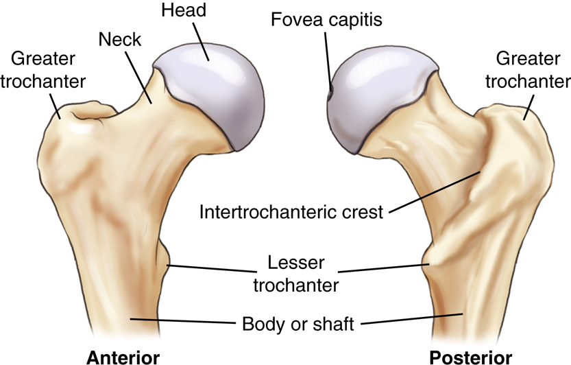
The proximal femur consists of four essential parts, the head (1), neck (2), and greater (3) and lesser trochanters (4) (tro-kan′-ters).
The head of the femur is rounded and smooth for articulation with the hip bones. It contains a depression, or pit, near its center called the
fovea capitis
(fo′-ve-ah cap′-i-tis), wherein a major ligament called the
ligament of the head of the femur,
or the
ligament capitis femoris,
is attached to the head of the femur.
The neck of the femur is a strong pyramidal process of bone that connects the head with the body or shaft in the region of the trochanters.
The greater trochanter is a large prominence located superiorly and laterally to the femoral shaft and is palpable as a bony landmark. The lesser trochanter is a smaller, blunt, conical eminence that projects medially and posteriorly from the junction of the neck and shaft of the femur. The trochanters are joined posteriorly by a thick ridge called the intertrochanteric (in″-ter-tro″-kan-ter′-ik) crest. The body or shaft of the femur is long and almost cylindrical (Fig. 7.2).
Angles of the Proximal Femur
The angle of the neck to the shaft on an average adult is approximately 125°, with a variance of ±15°, depending on the width of the pelvis and the length of the lower limbs. For example, in a long-legged person with a narrow pelvis, the femur would be nearer vertical, which then would change the angle of the neck to about 140°. This angle would be less (110° to 115°) for a shorter person with a wider pelvis.
On an average adult in the anatomic position, the longitudinal plane of the femur is approximately 10° from vertical, as shown on the left in Fig. 7.3. This vertical angle is nearer 15° on someone with a wide pelvis and shorter limbs and only about 5° on a long-legged person. This angle affects positioning and the central ray (CR) angles for a lateral knee, as described in Figs. 6.19 and 6.20.
Another angle of the neck and head of the femur that is important in radiography is the 15° to 20° anterior angle of the head and neck in relation to the body of the femur (see right drawing of Fig. 7.3). The head projects somewhat anteriorly or forward as a result of this angle. This angle becomes important in radiographic positioning; the femur and lower leg must be rotated 15° to 20° internally to place the femoral neck parallel to the image receptor (IR) for a true anteroposterior (AP) projection of the proximal femur.


Pelvis
The complete pelvis (meaning a basin) serves as the base of the trunk and forms the connection between the vertebral column and lower limbs. The pelvis consists of four bones—two hip bones (also called innominate bones), one sacrum (sa′-krum), and one coccyx (kok′-siks) (Fig. 7.4). The sacrum articulates superiorly with the fifth lumbar vertebra to form the lumbosacral joint (also called the L5–S1 joint). The right and left hip (iliac) bones articulate posteriorly with the sacrum to form the sacroiliac joints.
1
NOTE:The sacrum and the coccyx also are considered parts of the distal vertebral column and in this textbook are discussed in Chapter 9, along with the lumbar spine.
Hip Bone
Each hip bone is composed of three divisions: (1) ilium (il′-e-um), (2) ischium (is′-ke-um), and (3) pubis (pu′-bis). In a child, these three divisions are separate bones, but they fuse into one bone during the middle teens. The fusion occurs in the area of the acetabulum (as″-e-tab′-u-lum). The acetabulum is a deep, cup-shaped cavity that accepts the head of the femur to form the hip joint (Fig. 7.5).
The ilium, the largest of the three divisions, is located superior to the acetabulum. The ischium is inferior and posterior to the acetabulum, whereas the pubis is inferior and anterior to the acetabulum. Each of these three parts is described in detail in the following sections.
Ilium
Each ilium is composed of a body and an ala, or wing (Fig. 7.6). The body of the ilium is the more inferior portion near the acetabulum and includes the superior two-fifths of the acetabulum. The ala, or wing portion, is the thin and flared superior part of the ilium.
The crest of the ilium is the superior margin of the ala; it extends from the anterior superior iliac spine (ASIS) to the posterior superior iliac spine (PSIS). In radiographic positioning, the uppermost peak of the crest often is referred to as the iliac crest, but it actually extends between the ASIS and the PSIS.
Below the ASIS is a less prominent projection referred to as the anterior inferior iliac spine. Similarly, inferior to the PSIS is the posterior inferior iliac spine.
Positioning Landmarks
The two important positioning landmarks of these borders and projections are the iliac crest and the ASIS.


Ischium
The ischium is that part of the hip bone that lies inferior and posterior to the acetabulum. Each ischium is divided into a body and a ramus (Fig. 7.7). The superior portion of the body of the ischium makes up the posteroinferior two-fifths of the acetabulum. The lower portion of the body of the ischium (formerly called the superior ramus) projects caudally and medially from the acetabulum, ending at the ischial tuberosity. Projecting anteriorly from the ischial tuberosity is the ramus of the ischium.
The rounded roughened area near the junction of the lower body and the inferior rami is a landmark called the tuberosity of the ischium, or the ischial (is′-ke-al) tuberosity.
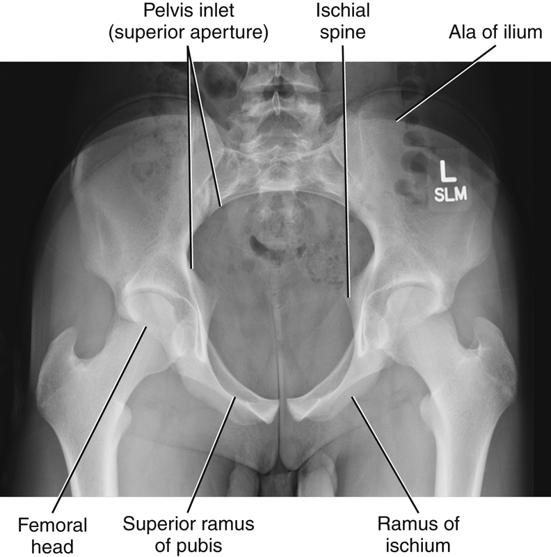
Posterior to the acetabulum is a bony projection termed the
ischial spine
. A small part of the ischial spine also is visible on a frontal view of the pelvis, as shown in Fig. 7.8. (It is also seen in the anatomy review radiograph; see Fig. 7.16.)
Directly superior to the ischial spine is a deep notch termed the
greater sciatic notch.
Inferior to the ischial spine is a smaller notch termed the
lesser sciatic notch.
Positioning Landmarks
The ischial tuberosities bear most of the weight of the body when an individual sits. They can be palpated through the soft tissues of each buttock in a prone position. However, because of discomfort and possible embarrassment to the patient, this landmark is not used as commonly as the previously described ASIS and crest of the ilium.
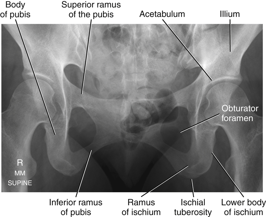
Pubis
The last of the three divisions of one hip bone is the pubis, or pubic bone. The body of the pubis is anterior and inferior to the acetabulum and includes the anteroinferior one-fifth of the acetabulum.
Extending anteriorly and medially from the body of each pubis is a superior ramus. The two superior rami meet in the midline to form an amphiarthrodial joint, the symphysis pubis (sim′-fi-sis pu′-bis), which also is correctly called the pubic symphysis. Each inferior ramus passes down and posterior from the symphysis pubis to join the ramus of the respective ischium.
The obturator foramen (ob′-tu-ra″-tor fo-ra′-men) is a large opening formed by the ramus and body of each ischium and by the pubis. The obturator foramen is the largest foramen in the human skeletal system.
Positioning Landmark
The crests of the ilium and ASIS are important positioning landmarks. The superior margin of the symphysis pubis is a possible landmark for pelvis and hip positioning and for positioning of the abdomen, because it defines the inferior margin of the abdomen. However, if other associated landmarks are available, the symphysis pubis generally is not used as a palpated landmark because of patient modesty and potential embarrassment.
Summary of Topographic Landmarks
Important positioning landmarks of the pelvis are reviewed in Fig. 7.9. The most superior aspects of the iliac crest and the ASIS are easily palpated. The ASIS is one of the more frequently used positioning landmarks of the pelvis. It also is commonly used to check for rotation of the pelvis and/or lower abdomen by determination of whether the distance between the ASIS and the tabletop is equal on both sides.
The greater trochanter of the femur can be located by firm palpation of the soft tissues of the upper thigh. Note that the prominence of the greater trochanter is at about the same level as the superior border of the symphysis pubis, whereas the ischial tuberosity is 1½ to 2 inches (4 to 5 cm) below the symphysis pubis. These distances vary between a male and a female pelvis because of general differences in shape, as described later in this chapter.


True and False Pelvis
A plane through the brim of the pelvis divides the pelvic area into two cavities. The pelvic brim is defined by the superior portion of the symphysis pubis anteriorly and by the superior, prominent part of the sacrum posteriorly. The general area above or superior to the oblique plane through the pelvic brim is termed the
greater,
or
false, pelvis.
The flared portion of the pelvis, which is formed primarily by the alae, or wings, of the ilia, forms the lateral and posterior limits of the false pelvis, whereas the abdominal muscles of the anterior wall define the anterior limits. The lower abdominal organs rest on the floor of the greater pelvis, as does the fetus within a pregnant uterus.
The area inferior to a plane through the pelvic brim is termed the
lesser,
or
true, pelvis.
The true pelvis is a cavity that is completely surrounded by bony structures. The size and shape of the true pelvis are of greatest importance during the birth process because the true pelvis forms the actual birth canal (Fig. 7.10).
True Pelvis
The oblique plane defined by the brim of the pelvis is termed the
inlet,
or
superior aperture,
of the true pelvis. The outlet, or inferior aperture, of the true pelvis is defined by the two ischial tuberosities and the tip of the coccyx (Fig. 7.11). The three sides of the triangularly shaped outlet are formed by a line between the ischial tuberosities and a line between each ischial tuberosity and the coccyx. The area between the inlet and outlet of the true pelvis is termed the
cavity
of the true pelvis. During the birth process, the baby must travel through the inlet, cavity, and outlet of the true pelvis.
Birth Canal
During a routine delivery, the baby’s head first travels through the pelvic inlet, then to the midcavity, and finally through the outlet before it exits in a forward direction, as shown in Fig. 7.12.
Because of sensitivity of the fetus to radiation, radiographs of the pelvis generally are not taken during pregnancy. If the dimensions of the birth canal of the pelvis are in question, certain ultrasound procedures can be done to evaluate for potential problems during the birth process.
Pelvic Ring
The pelvic ring is a term applied in orthopedics describing the sturdy, ringlike structure formed by the union of the ilium, ischium, and pubic bones, along with the sacrum and coccyx. This term is often used in described specific fractures that can disrupt the alignment of these bones.
2
Male Versus Female Pelvis Differences 3
There are four common shapes of the human pelvic inlet:
The general shape of the female pelvis is different enough from that of the male pelvis to enable discrimination of one from the other on pelvis radiographic images. In general, the female pelvis is wider, with the ilia more flared and more shallow from front to back (gynecoid or platypelloid). The male pelvis is narrower, deeper (anthropoid), or less flared with a heart-shaped pelvic inlet (android). In overall appearance on a frontal view, the female pelvis is wider with a round pelvic inlet. Therefore, the first difference between the male pelvis and female pelvis is the difference in the overall general shape of the entire pelvis, along with the shape differences of the pelvic inlet (Fig. 7.13).


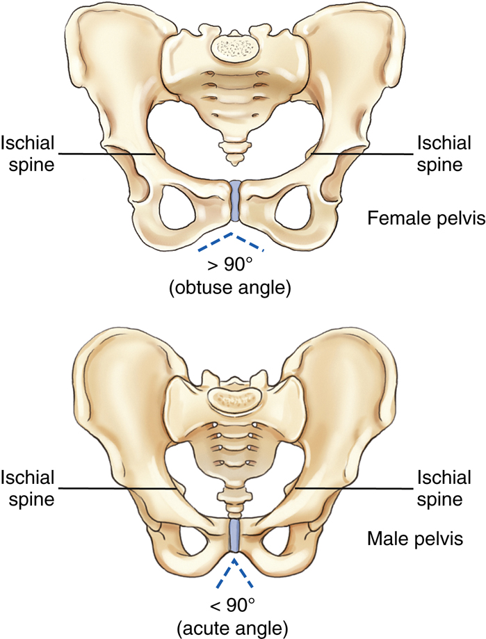
A second major difference is the angle of the pubic arch, formed by the inferior rami of the pubis just inferior to the symphysis pubis. In the female, this angle is between 80° and 85°, whereas in the male, the pubic arch usually forms an acute angle between 50° and 60°.
A third difference is that the ischial spines generally do not project as far medially toward the pelvic cavity in the female as they do in males. They are more visible along the lateral margins of the pelvic cavity in the male than in the female in the AP pelvis projection.
NOTE: The general shape of the pelvis does vary considerably from one individual to another, so the pelvis of a slender female may resemble a male pelvis. In general, however, the differences are usually obvious enough that the gender of the patient can be determined from a radiographic image of the pelvis.
See Table 7.1 for a summary of male and female pelvic characteristics.
TABLE 7.1
Male Versus Female Pelvis Radiographs
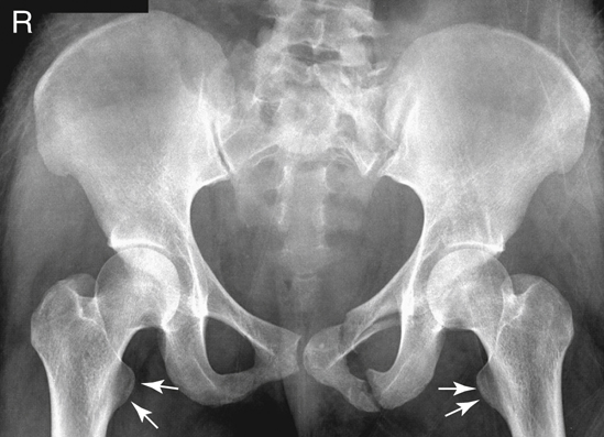
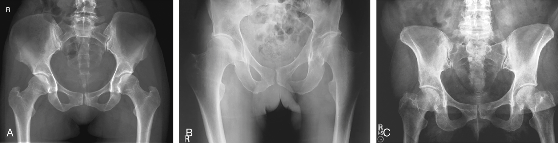
Figs. 7.14 and 7.15 are pelvic radiographs of a female subject and a male subject, respectively. Note the three differences between the typical female pelvis and typical male pelvis.
- 1. In overall shape, the male pelvis appears narrower and deeper and has a less-flared appearance of the ilia. The shape of the inlet on the male pelvis is not as large or as rounded as that of the female pelvis.
- 2. The pubic arch of the male pelvis has a smaller angle compared to the greater angle on the female pelvis. This angle is commonly one of the more noticeable differences.
- 3. Radiographic presence of the ischial spines along the lateral margins of the pelvic cavity is less pronounced with the female pelvis.


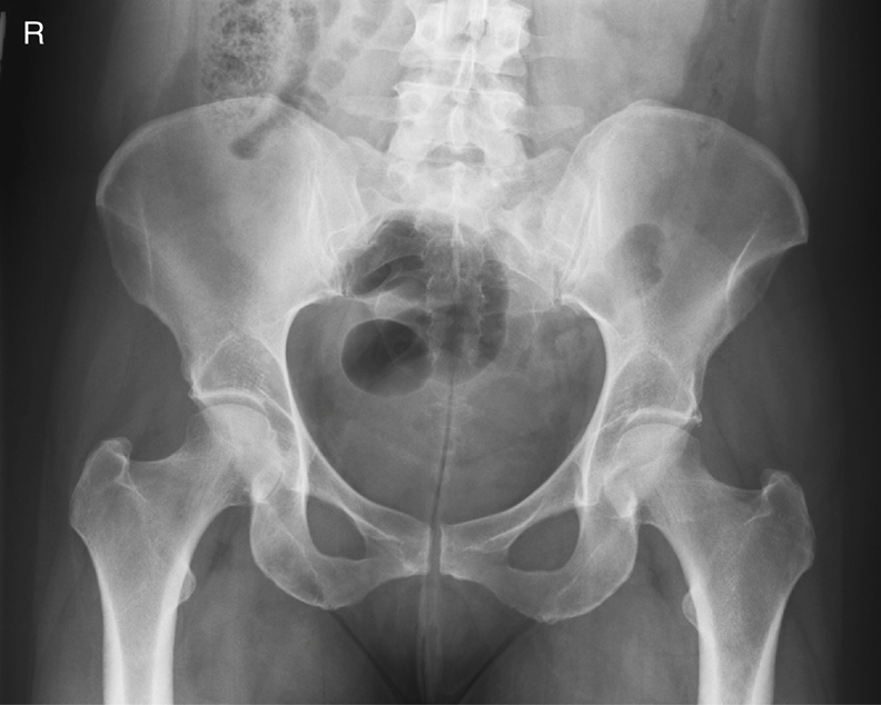
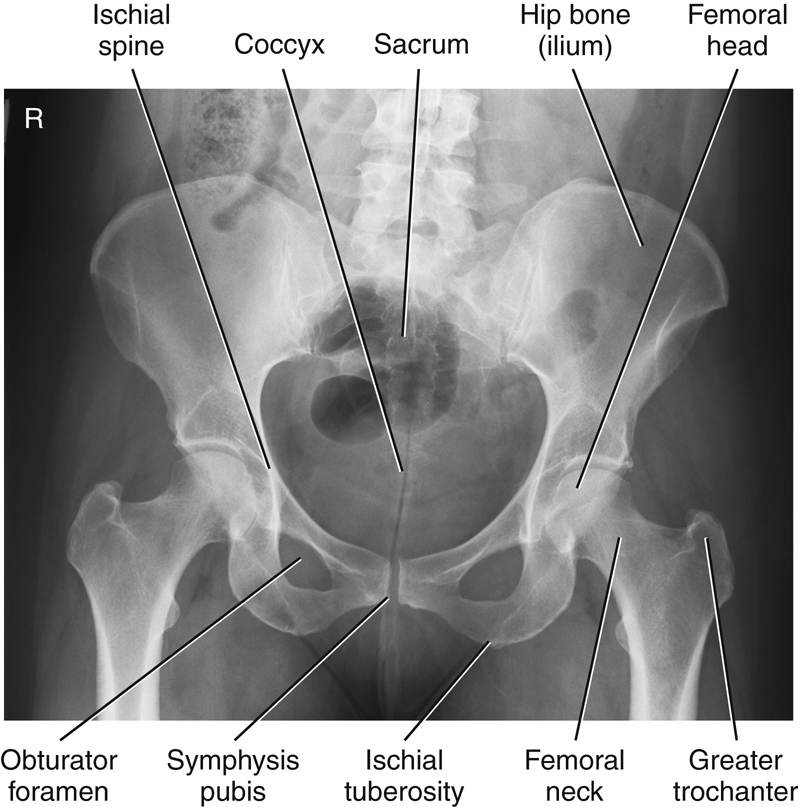
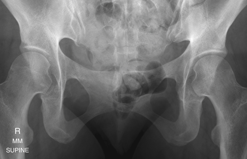
Review Exercise with Radiographs
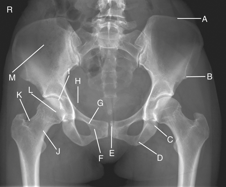
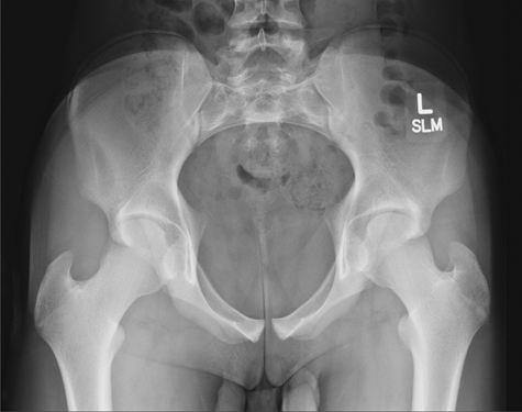
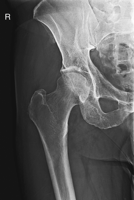
Key pelvic anatomy is labeled on the AP pelvis radiograph of Fig. 7.16. A good review exercise is to cover up the answers (listed below) while identifying the labeled parts.
- A. Iliac crest
- B. ASIS (anterior end of crest)
- C. Body of left ischium
- D. Ischial tuberosity
- E. Symphysis pubis (pubic symphysis)
- F. Inferior ramus of right pubis
- G. Superior ramus of right pubis
- H. Right ischial spine
- I. Acetabulum of right hip
- J. Neck of right femur
- K. Greater trochanter of right femur
- L. Head of right femur
- M. Ala, or wing, of right ilium
Lateral Hip
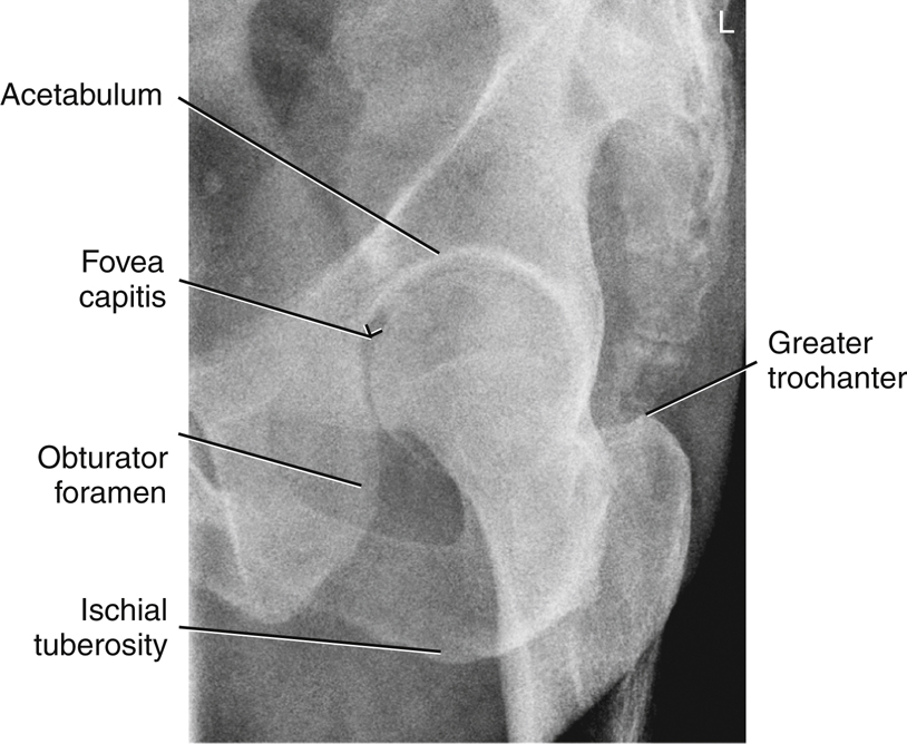
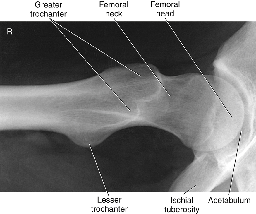
Fig. 7.17 presents a lateral radiograph of the proximal femur and hip, taken with an axiolateral projection (Danelius-Miller method), as demonstrated by the positioning in Fig. 7.18. Answers to the labeled parts are as follows:


Classification Of Joints (FIG. 7.19)
The number of joints or articulations of the proximal femora and pelvis is limited, with the hip joint being the most obvious. These joints of the pelvis, in the following list, again are described according to their classification, mobility type, and movement type.
-
- Sacroiliac joints: joints between the sacrum and each ilium
- Symphysis pubis: structure between the right and left pubic bones
- Union of acetabulum: temporary growth joint of each acetabulum that solidifies in the midteen years
- Hip joints: joints between the head of the femur and the acetabulum of the pelvis
Sacroiliac Joints (Fig. 7.20)
The sacroiliac joints are wide flat joints located on each side obliquely between the sacrum and each ilium. These joints are situated at an unusual oblique angle, requiring special positioning to visualize the joint spaces radiographically.
The sacroiliac joint is classified as a synovial joint in that it is enclosed in a fibrous articular capsule that contains synovial fluid. The bones are joined by firm sacroiliac ligaments. Generally, synovial joints by their nature are considered freely movable, or diarthrodial, joints. However, the sacroiliac joint is a special type of synovial joint that permits little movement. Due to its unique structure and movement, it’s type of movement is irregular gliding. The reason for this classification is that the joint surfaces are very irregularly shaped and the interconnecting bones are snugly fitted because they serve a weight-bearing function. This shape restricts movement, and the cavity of the joint or the joint space may be reduced in size or even nonexistent in older persons, especially in males. Positioning of the sacroiliac joints is described in Chapter 9.
Symphysis Pubis
The symphysis pubis is the articulation of the right and left pubic bones located in the midline of the anterior pelvis. The most superior anterior aspect of this joint is palpable and is an important positioning landmark, as described earlier.
The symphysis pubis is classified as a cartilaginous joint of the symphysis subtype in that only limited movement is possible (amphiarthrodial). The two articular surfaces are separated by a fibrocartilaginous disk and are held together by certain ligaments. This interpubic disk of fibrocartilage is a relatively thick pad (thicker in females than males) that is capable of being compressed or partially displaced, thereby allowing limited movement of these bones, as in the case of pelvic trauma or during the childbirth process in females.
Union of Acetabulum
The three divisions of each hip bone are separate bones in a child but come together in the acetabulum by fusing during the middle teens to become completely indistinguishable in an adult. Therefore, this structure is classified as a cartilaginous-type joint of the synchondrosis subtype, which is immovable, or synarthrodial, in an adult. This joint is considered a temporary type of growth joint that is similar to the joints between the epiphyses and diaphyses of long bones in growing children.
Hip Joint
The hip joint is classified as a synovial type, which is characterized by a large fibrous capsule that contains synovial fluid. It is a freely movable, or diarthrodial, joint and is the truest example of a ball and socket (spheroidal) movement type. See Table 7.2 for a summary of the pelvic joints.
The head of the femur forms more than half a sphere as it fits into the relatively deep, cup-shaped acetabulum. This connection makes the hip joint inherently strong as it supports the weight of the body while still permitting a high degree of mobility. The articular capsule surrounding this joint is strong and dense, with the thickest part being superior, as would be expected because it is in line with the weight-bearing function of the hip joints. A series of strong bands of ligaments surround the articular capsule and joint in general, making this joint very strong and stable.
Movements of the hip joint include flexion and extension, abduction and adduction, medial (internal) and lateral (external) rotation, and circumduction.


TABLE 7.2

Radiographic Positioning
Positioning Considerations
Locating the Femoral Head and Neck
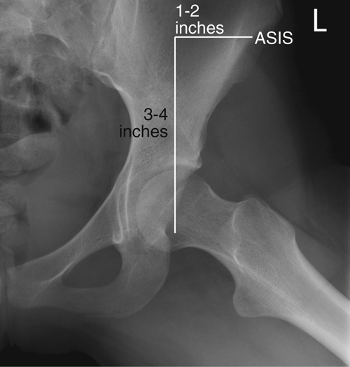
A long-standing traditional method used to locate the femoral head and neck is first to determine the midpoint of a line between the ASIS and the symphysis pubis. The neck is approximately 2½ inches (6 to 7 cm), and the head 1½ inches (4 cm) distal and at right angles to the midpoint of this line (Figs. 7.21 and 7.22).
The greater trochanters are shown to be located on the same horizontal line as the symphysis pubis. However, the greater trochanters are difficult to palpate accurately on large or bariatric patients, and palpation of the symphysis pubis can be embarrassing for the patient. Therefore, a second method is suggested for locating the femoral head or neck that uses only the ASIS, which is easily palpated on all types of patients. The level of the symphysis pubis is between 3 and 4 inches (8 to 10 cm) inferior to the level of the ASIS. Therefore, the femoral neck can be readily located as being 1 to 2 inches (3 to 5 cm) medial and 3 to 4 inches (8 to 10 cm) distal to the ASIS. This level also places it on the same horizontal plane as the symphysis pubis and the greater trochanters.
As was previously demonstrated, significant differences exist between the male pelvis and the female pelvis, but with some practice and allowances for male and female differences, both of these methods work well for locating the femoral head or neck for hip positioning.
Appearance of Proximal Femur in Anatomic Position
As was described earlier in this chapter under anatomy of the proximal femur, the head and neck of the femur project approximately 15° to 20° anteriorly or forward with respect to the rest of the femur and the lower leg. Thus, when the leg is in the true anatomic position, as for a true AP leg, the proximal femur actually is rotated posteriorly 15° to 20° (Fig. 7.23). Therefore, the femoral neck appears shortened and the lesser trochanter is visible when the leg and ankle are truly AP, as in a true anatomic position.
Internal Rotation of Leg
By internally rotating the entire lower limb, the proximal femur and hip joint are positioned in a true AP projection. The neck of the femur is now parallel to the imaging surface and will not appear foreshortened.
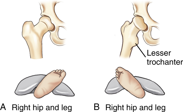
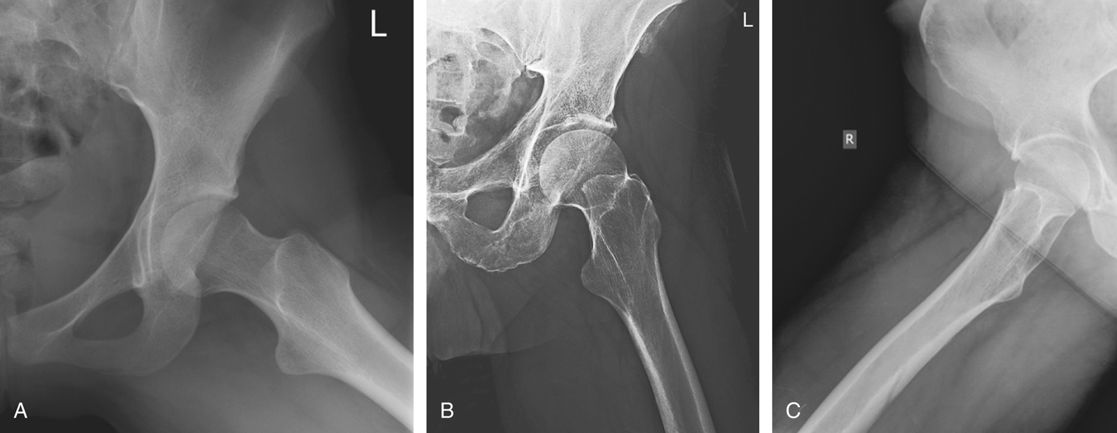
The lesser trochanter is key in determining the correct leg and foot position (on a radiographic image). If the entire leg is rotated internally a full 15° to 20° (Fig. 7.24A), the outline of the lesser trochanter generally is not visible at all or is only slightly visible on some patients, when it is obscured by the shaft of the femur. If the leg is straight AP, or when it is externally rotated, the lesser trochanter is visible (see page 274).
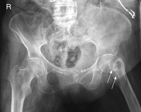
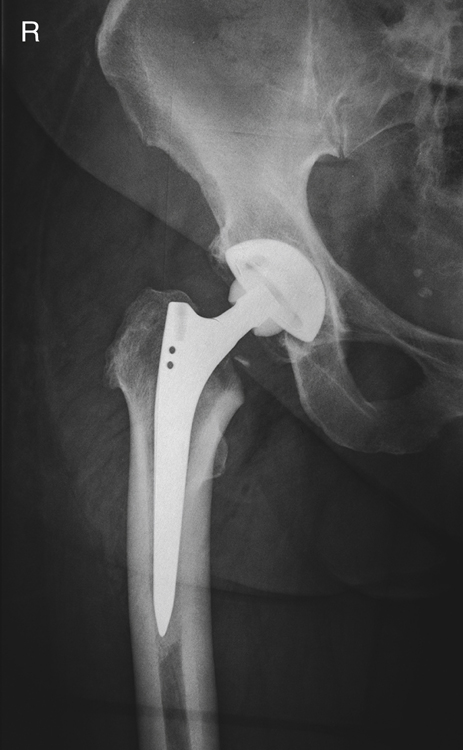
Evidence of Hip Fracture
The femoral neck is a common fracture site for an older patient who has fallen. The typical physical sign for such a fracture is the external rotation of the involved foot, where the lesser trochanter is clearly visualized in profile, as can be seen on the left hip depicted in Fig. 7.32 and the drawing on the right (Fig. 7.24B). This radiographic sign is demonstrated on the following page (see Figs. 7.31 and 7.32).
WARNING: If evidence of a hip fracture is present (external foot rotation), a pelvis radiograph should be taken “as is” without attempting to rotate the leg internally, as would be necessary for a true AP hip projection.


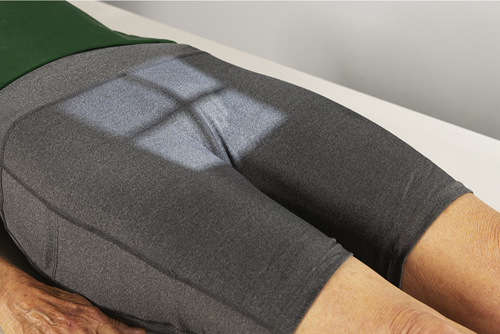
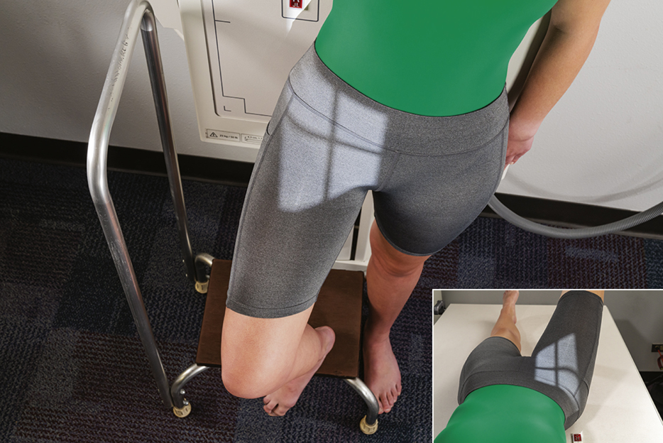
Summary: Effect of Lower Limb Rotation
The photographs and associated pelvis radiographs on this page demonstrate the effects of lower limb rotation on the appearance of the proximal femora.


Shielding Guidelines
Accurate gonadal shielding for pelvis and hip examinations is especially critical because of the proximity of radiation-sensitive gonads to the primary x-ray beam.
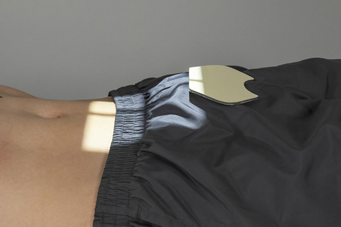
Male Shielding
Shielding is easier for males in that small contact shields, such as those shown in Fig. 7.33, can be used on all males. These shields are placed over the area of the testes without covering the essential anatomy of the pelvis or hips. However, care must be taken with pelvic radiographs that the top of the shield is placed at the inferior margin of the symphysis pubis to cover the testes adequately without obscuring the pubic and ischial areas of the pelvis.
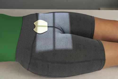
Female Shielding
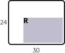
Ovarian contact shields for females require more critical placement to shield the area of the ovaries without covering essential pelvic or hip anatomy. Vinyl-covered lead material cut into various shapes and sizes can be used for this purpose for an AP pelvis or bilateral hip radiograph, as shown in Fig. 7.34. For a unilateral hip or proximal femur, larger contact shields can be used to cover the general pelvic area without covering the specific hip that is being examined, as shown in Fig. 7.35. Accurate location of the femoral head and neck makes this type of gonadal shielding possible.
Gonadal shielding may not be possible for females on certain AP pelvic projections in which the entire pelvis, including the sacrum and coccyx, must be demonstrated. Also, gonadal shielding may not be possible on lateral inferosuperior hip projections for males and females because shielding may obscure essential anatomy. However, gonadal shielding should be used whenever possible for both males and females, along with close collimation for all hip and pelvic projections. General pelvic trauma requiring visualization of the entire pelvis may prohibit ovarian shielding for females.
Exposure Factors and Patient Dose
To reduce total radiation dose to the patient, a higher kVp range of 80 to 90 may be used for hip and pelvic examinations. This higher kVp technique, with lower mAs, results in a lower radiation dose to the patient. Higher kVp, however, decreases subject contrast and may not be advisable, especially for older patients, who may have some loss of bone mass or density caused by osteoporosis; thus, they may require even lower kVp than average. Overexposure with high kVp on osteoporotic patients will decrease the visibility of the bony detail when using both analog and digital imaging systems.
Special Patient Considerations
Pediatric Applications
Pelvic and hip radiographic examinations are not performed often on children, except on newborns with developmental dysplasia of the hip (DDH). Correct shielding is especially important for infants and children because of the repeat radiographic examinations that are frequently required during the growth of the child. If holding the legs of an infant is required, an individual other than radiology personnel should do this while wearing a lead apron and lead gloves.
The degree and type of immobilization required for older children are dependent on the ability and willingness of the child to cooperate during the procedure. A mummy wrap (see Chapter 16) helps prevent the upper limbs from interfering with the anatomy of interest on a challenging patient. At the very least, tape or sandbags may be required to immobilize the legs at the proper degree of internal rotation.
Geriatric Applications
Geriatric patients are prone to hip fractures resulting from falls and an increased incidence of osteoporosis. As noted earlier, the position of the patient’s foot and leg must be observed in trauma cases. It is critical that the injured limb not be moved if the leg is externally rotated. An AP projection of both hips for comparison should be taken first, without movement of the affected limb, to check for fractures. This step may be followed by an inferosuperior (Danelius-Miller method) projection of the affected hip.
In nontrauma situations, most geriatric patients require (and appreciate) some immobilization to assist them in holding their feet and legs inverted for the AP pelvis and to support the limb for the lateral projection.

Bariatric Patient Considerations
Bariatric patients may present positioning challenges when imaging the pelvis, hips, and upper femurs. Increased adipose tissue adds subject density and may require an increase in technical factors. These changes may include an increase in kVp to improve penetration through additionally thick tissue. mA and time may also be increased, but sparingly to avoid excessive patient dose. The use of a grid for anatomic structures over 10 cm can be used to eliminate the demonstration of scatter.
Frequently used positioning landmarks may be difficult to palpate. Bony anatomy does not change unless major pathology, such as multiple fractures, has displaced the bones. Although the soft tissue may make it appear that the bones are larger or are farther apart, generally this is not the case. If common landmarks cannot be found, ask the patient to point out the ASIS, iliac crest, or the symphysis pubis on themselves. Additionally, bariatric patients may have difficulty holding oblique or lateral positions; the use of positioning sponges or other devices is recommended to ensure the patient’s comfort and safety.
Digital Imaging Considerations
The following text provides a summary of the guidelines that should be followed with digital imaging of the procedures described in this chapter.
- 1. Close collimation: Collimating to the body part being imaged and accurate centering are most important when imaging the hip and pelvis.
- 2. Exposure factors: It is important that the ALARA principle (exposure to patient as low as reasonably achievable) be followed and the lowest exposure factors required to obtain a diagnostic image be used. This includes the highest kVp and lowest mAs that will result in desirable image quality.
- 3. Post-processing evaluation of exposure indicator: The exposure indicator on the final processed image must be checked to verify the exposure factors used were in the correct range to ensure an optimum quality image with the least radiation dose to the patient.
- 4. Compensating filters: The use of a compensating filter for axiolateral projections of the hip will allow better penetration of the femoral head while preventing overexposure of the femoral neck and shaft region.
Alternative Modalities
Computed Tomography (CT)
CT is useful for evaluating soft tissue involvement of lesions or determining the extent of fractures. CT also is helpful for studying the relationship of the femoral head to the acetabulum before hip surgery or for performing a postreduction study of a developmental hip dislocation.
In general, CT is useful to add to the anatomic or pathologic information already obtained by conventional radiography. For children, the CT examination is useful for examining the relationship of the femoral head to the acetabulum after surgical reduction of a developmental hip dislocation.
Fractures of the pelvic ring missed on conventional radiographic projections, especially those involving the ischial and pubic rami, often are demonstrated during CT scanning.
Magnetic Resonance Imaging (MRI)
Similar to CT, MRI can be useful for imaging the lower limb or pelvis when soft tissue injuries or possible abnormalities related to joints are suspected. In general, depending on clinical history, MRI may be used when additional information not obtained from conventional radiographs is needed.
Sonography (Ultrasound)
Ultrasound is useful for evaluating newborns for hip dislocation and for assessing joint stability during movement of the lower limbs. This method usually is selected during the first 4 to 6 months of infancy to reduce ionizing radiation exposure.
Nuclear Medicine (NM)
NM scans can be useful in providing early evidence of certain bony pathologic processes, such as occult fractures, bone infections, metastatic carcinoma, or other metastatic or primary malignancies. NM is more sensitive and generally provides earlier evidence than other modalities because it assesses the physiologic aspect rather than the anatomic aspect of these conditions.
Clinical Indications
Clinical indications involving the pelvis and hips with which technologists should be familiar include the following (not necessarily an inclusive list):
- Ankylosing spondylitis: The first effect demonstrated is fusion of the sacroiliac joints. The disease causes extensive calcification of the anterior longitudinal ligament of the spinal column. It is progressive, working up the vertebral column and creating a radiographic characteristic known as bamboo spine. Males are most often affected.
- Avulsion fractures of the pelvis: These fractures cause extreme pain and are difficult to diagnose if not imaged properly. Fractures occur in adolescent athletes who experience sudden, forceful, or unbalanced contraction of the tendinous and muscular attachments, such as might occur while running hurdles. The force of the tendons and muscles sliding over the tuberosities, ASIS, anterior inferior iliac spine (AIIS), superior corner of the symphysis pubis, and iliac crest may cause avulsion fractures. 4
- Chondrosarcoma: A malignant tumor of the cartilage, it usually occurs in the pelvis and long bones of men older than 45 years. A chondrosarcoma may be completely removed surgically if it does not respond to radiation or chemotherapy.
- Developmental dysplasia of the hip (DDH) (older term is congenital dislocation of the hip [CDH]): These hip dislocations are caused by conditions present at birth and may require frequent hip radiographs (see Chapter 16).
- Legg-Calvé-Perthes disease: The most common type of aseptic or ischemic necrosis. Lesions typically involve only one hip (head and neck of femur). The disease occurs predominantly in 5- to 10-year-old boys, and a limp is usually the first clinical sign. Radiographs demonstrate a flattened femoral head that later can appear fragmented.
- Metastatic carcinoma: The malignancy spreads to the bone via the circulatory system or lymphatic system, or by direct invasion. Metastatic tumors of the bone are much more common than primary malignancies. Bones that contain red bone marrow are the more common metastatic sites (spine, skull, ribs, pelvis, and femora).
- Osteoarthritis: This condition is known as a degenerative joint disease (DJD), with degeneration of joint cartilage and adjacent bone causing pain and stiffness. It is the most common type of arthritis and may be considered a normal part of the aging process. It is common in weight-bearing joints such as the hips, and first evidence is seen on radiographic images of joints such as the hip before symptoms develop, in many persons by age 40. As the condition worsens, joints become less mobile, and new growths of cartilage and bone are seen as osteophytes (bony outgrowths).
- Pelvic ring fractures: Because of the closed ring structure of the pelvis, a severe blow or trauma to one side of the pelvis may result in a fracture opposite from the site of primary trauma, thus requiring clear radiographic visualization of the entire pelvis. This type of trauma is referred to as a contrecoup injury.
- Proximal femur (hip) fractures: These fractures are most common in older adult or geriatric patients with osteoporosis or avascular necrosis. Both osteoporosis (loss of bone mass from metabolic or other factors) and avascular (loss of blood circulation) necrosis (cell death) frequently lead to weakening or collapse of weight-bearing joints such as the hip joint; fractures occur with only minimal trauma.
- Slipped capital femoral epiphysis (SCFE): This condition usually occurs in 10- to 16-year-olds during rapid growth, when even minor trauma can precipitate its development. The epiphysis appears shorter and the epiphyseal plate wider, with smaller margins.
Routine and Special Projections
AP Projection: Femur—MID and Distal
NOTE: If the site of interest is in the area of the proximal femur, a unilateral hip routine or pelvis is recommended, as described in this chapter.
Clinical Indications
Technical Factors

Shielding
Shield radiosensitive tissues outside the region of interest. Ensure that shielding does not obscure any aspect of the femur.
Patient Position
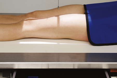
Place patient in the supine position, with femur centered to midline of table; give pillow for head. (This projection also may be done on a stretcher with a portable grid placed under the femur.)
Part Position

- • Align femur to CR and to midline of table or IR.
- • Rotate leg internally approximately 5° for a true AP, as for an AP knee. (For proximal femur, 15° to 20° internal leg rotation is required, as for an AP hip.)
- • Ensure that knee joint is included on IR, considering the divergence of the x-ray beam (Fig. 7.36). (Lower IR margin should be approximately 2 inches [5 cm] below knee joint.)
CR
Recommended Collimation
Collimate closely on both sides to femur with end collimation to film borders.
Including both Joints
Common departmental routines include both joints on all initial femur exams. For a large adult, a second smaller IR then should be used for an AP of the knee or hip, ensuring that both hip and knee joints are included. If the hip is included, the leg should be rotated 15° to 20° internally to place the femoral neck in profile.

Lateral—Mediolateral or Lateromedial Projections: Femur—Mid And Distal
NOTE: For possible trauma, if the site of interest is in the area of the proximal femur, a unilateral trauma hip routine is recommended. For nontrauma, lateral of proximal femur (see p. 290).
Clinical Indications
Technical Factors

Shielding
Shield radiosensitive tissues outside region of interest. Ensure shielding does not obscure any aspect of femur.
Patient Position
Place patient in the lateral recumbent position, or supine for trauma patient.
Part Position
Lateral Recumbent (Fig. 7.38)
WARNING:Do not attempt this position if patient has severe trauma.
- • Flex knee approximately 45° with patient on affected side, and align femur to midline of table or IR.
- • Place unaffected leg behind affected leg to prevent over-rotation.
- • Adjust IR to include knee joint (lower IR margin should be approximately 2 inches [5 cm] below knee joint). A second IR to include the proximal femur and hip generally will be required on an adult (see p. 290).
Trauma Lateromedial Projection (Fig. 7.39)
CR
Recommended Collimation
Collimate closely on both sides to femur with end collimation to IR borders.

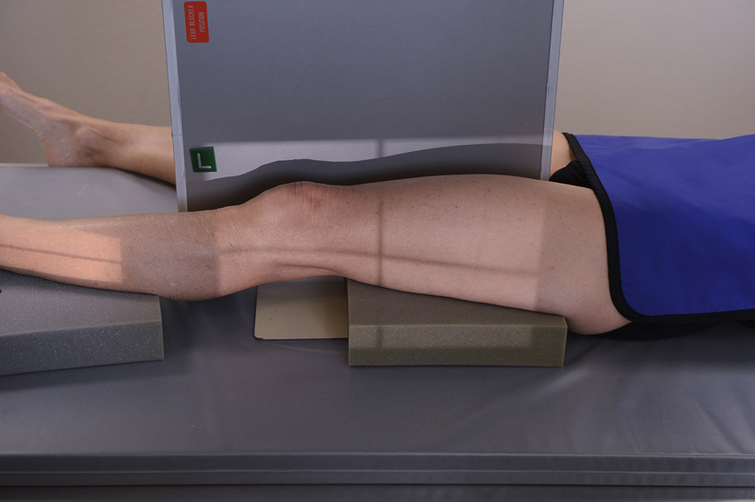

Lateral—Mediolateral Projection: Femur—MID and Proximal
WARNING: Do not attempt this position for patients with possible fracture of the hip or proximal femur. Refer to trauma lateral hip routine in this chapter.
Clinical Indications
Technical Factors

Shielding
Shield radiosensitive tissues outside region of interest. Ensure shielding does not obscure any aspect of femur.
Patient Position
Place patient in the lateral recumbent position, with affected side down; provide pillow for head.
Part Position
- • Flex affected knee 45° and align femur to midline of table. (Remember the proximal and midportions of the femur are nearer to the anterior aspect of the thigh.)
- • Extend and support unaffected leg behind affected knee and have patient roll back (posteriorly) 15° to prevent superimposition of proximal femur and hip joint (Fig. 7.41).
- • Adjust IR to include hip joint, considering the divergence of the x-ray beam. (Palpate ASIS and place upper IR margin at the level of this landmark.)
CR
Recommended Collimation
Collimate closely on both sides of femur with end collimation to IR borders.
NOTE: Alternate routine to include both joints: Common departmental routines include both joints on all initial femur examinations. On a large adult, this requires a second smaller IR (10 x 12 inches [24 x 30 cm]) of the hip or knee joint.


AP Pelvis Projection (Bilateral Hips): Pelvis
WARNING:Do not attempt to rotate legs internally if a hip fracture or dislocation is suspected. Perform position with minimal movement of affected leg.
Clinical Indications
Technical Factors
Shielding
Shield radiosensitive tissues outside the region of interest. Shield gonads on all male patients. Ovarian shielding on females, however, generally is not possible without obscuring essential pelvis anatomy (unless interest is in area of hips only).
Patient Position
With patient supine, place arms at sides or across upper chest; provide pillow for head and support under knees; may be done erect with correction of lower limbs to rotate proximal femora into anatomic position and if no fracture is suspected. Position can also be performed erect.
Part Position
- • Align midsagittal plane of patient to centerline of table and CR.
- • Ensure that pelvis is not rotated; distance from tabletop to each ASIS should be equal.
- • Separate legs and feet, then internally rotate long axes of feet and entire lower limb 15° to 20° (see WARNING). Technologist may have to place sandbag between heels and tape top of feet together or use additional sandbags against feet to retain this position (Fig. 7.44, insert). Erect positioned similar to recumbent version (Fig. 7.44)
CR
Recommended Collimation
Collimate on four sides to anatomy of interest.
Respiration
Suspend respiration during exposure.

AP Bilateral Frog-Leg Projection: Pelvis
Modified Cleaves Method
WARNING:Do not attempt this position on a patient with destructive hip disease or with potential hip fracture or dislocation.
Clinical Indications
Technical Factors

Shielding
Shield radiosensitive tissues outside the region of interest. Shield gonads for both males and females without obscuring essential anatomy (see NOTE 1).
Patient Position
With patient supine, provide pillow for head and place arms across chest.
Part Position
- • Align patient to midline of table and/or IR and to CR.
- • Ensure pelvis is not rotated (equal distance of ASIS to tabletop).
- • Center IR to CR, at level of femoral heads, with top of IR approximately at level of iliac crest.
- • Flex both knees approximately 90°, as demonstrated.
- • Place the plantar surfaces of feet together and abduct both femora 40° to 45° from vertical (see NOTE 2). Ensure that both femora are abducted the same amount and that pelvis is not rotated (Fig. 7.47).
- • Place supports under each leg for stabilization if needed.
CR
Recommended Collimation
Collimate on four sides to anatomy of interest.
Respiration
Suspend respiration during exposure.
NOTE 1: This projection frequently is performed for periodic follow-up examinations on younger patients. Correct placement of gonadal shielding is important for male and female patients, ensuring that hip joints are not obscured (Fig. 7.48).


AP Axial Outlet Projection 5 (For Anterior-Inferior Pelvic Bones): Pelvis
Taylor Method
Clinical Indications
Technical Factors

Shielding
Shield radiosensitive tissues outside region of interest.
Patient Position
With patient supine, provide pillow for head. With patient’s legs extended, place support under knees for comfort (Fig. 7.49).
Part Position
CR
- • Angle CR cephalad 20° to 35° for males and 30° to 45° for females. (These different angles are caused by differences in the shape of male and female pelvises. See section Male Versus Female Pelvis Differences on pg. 270.)
- • Direct CR to a midline point 1 to 2 inches (2.5 to 5 cm) distal to the superior border of the symphysis pubis or greater trochanters.
Recommended Collimation
Collimate on four sides to anatomy of interest.
Respiration
Suspend respiration during exposure.
AP Axial Inlet Projection 5 : Pelvis
Clinical Indications
Technical Factors

Shielding
Shield radiosensitive tissues outside region of interest. Gonadal shielding is possible for males if care is taken not to obscure essential pelvic anatomy.
Patient Position
With patient supine, provide pillow for head. With patient’s legs extended, place support under knees for comfort (Fig. 7.52).
Part Position
CR
Recommended Collimation
Collimate closely on four sides to area of interest.
Respiration
Suspend respiration during exposure.

Posterior Oblique Projection: Pelvis—Acetabulum
Judet Method
Clinical Indications
Right and left oblique projections generally are taken for comparison, with both centered for upside or both for downside acetabulum. Possible pelvic ring fractures due to a contrecoup injury, the entire pelvis must be included. In this case, centering should be adjusted to include both hips.
Technical Factors

Shielding
Shield radiosensitive tissues outside region of interest.
Patient Position—Posterior Oblique Positions
Part Position
CR
Acetabulum
Pelvic Ring
- • Direct CR perpendicular and centered to 2 inches (5 cm) inferior from level of ASIS and 2 inches (5 cm) medial to upside ASIS. (Figs. 7.55 and 7.56)
Recommended Collimation
Respiration


Case courtesy Dr Luke Danaher, Radiopaedia.org, rID: 39777.

Case courtesy Dr Luke Danaher, Radiopaedia.org, rID: 39777.
PA Axial Oblique Projection: Acetabulum
Teufel Method
Clinical Indications
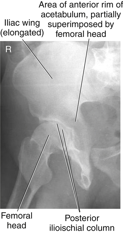
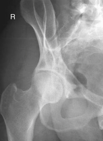
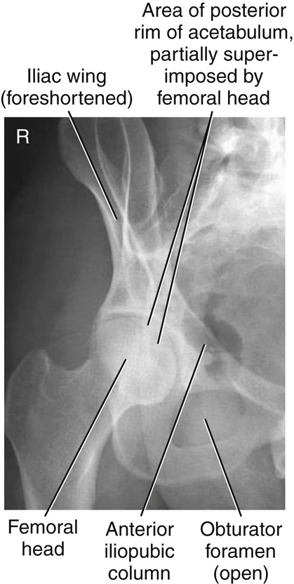
Right or left posterior oblique is taken to demonstrate the side of interest, centered to the downside acetabulum to demonstrate the hip joint and acetabulum in the center of the image, with the femoral head in profile. The concave area of the fovea capitis should be demonstrated, along with the superoposterior wall of the acetabulum.
Technical Factors

Shielding
Shield radiosensitive tissues outside region of interest.
Patient Position—Axial Oblique Positions
Part Position
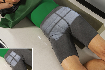
- • Place patient in anterior oblique, with both pelvis and thorax 35° to 40° from tabletop or wall bucky. Support with wedge sponge (Fig. 7.63).
- • Align femoral head and acetabulum of interest to midline of tabletop and/or IR.
- • Center IR longitudinally to CR at level of femoral head.
CR
Recommended Collimation
Collimate on four sides to anatomy of interest.
Respiration
Suspend respiration for the exposure.


AP Unilateral HIP Projection: HIP and Proximal Femur
WARNING:Do not attempt to rotate legs if fracture is suspected. An AP pelvis projection to include both hips for comparison should be completed before an AP unilateral hip is performed for possible hip or pelvis trauma.
Clinical Indications
Technical Factors

Shielding
Shield radiosensitive tissues outside region of interest.
Patient Position
With patient supine, place arms at sides or across superior chest.
Part Position
CR
- • CR is perpendicular to the femoral neck (see p. 273 for femoral head and neck localization methods). Femoral neck can also be located about 1 to 2 inches (2.5 to 5 cm) medial and 3 to 4 inches (8 to 10 cm) distal to ASIS (Fig. 7.66).
Recommended Collimation
Collimate on four sides to anatomy of interest.
Respiration
Suspend respiration during exposure.

Axiolateral Inferosuperior Projection—Trauma: Hip and Proximal Femur
Danelius-Miller Method
WARNING: Do not attempt to rotate leg internally on initial trauma examination.
NOTE: This is a common projection for trauma, surgery, and postsurgery patients, in addition to patients who cannot move or rotate the affected leg for frog-leg lateral.
Clinical Indications
Technical Factors
Shielding
Shield radiosensitive tissues outside region of interest. Gonadal shielding, if used, must be carefully placed to not obscure any anatomy of the affected hip. Close collimation is important for reducing patient dose and improving image quality.
Patient Position
May be done on stretcher or bedside if patient cannot be moved (see Chapter 15). Patient is supine, with pillow provided for head; elevate pelvis 1 to 2 inches (2.5 to 5 cm) if possible by placing supports under pelvis (more important for thin patients and for patients on a soft pad or in a bed).
Part Position (Figs. 7.69 and 7.70)
- • Flex and elevate unaffected leg so that thigh is near vertical position and outside collimation field. Support in this position. (Do NOT place leg on collimator or x-ray tube due to risk of burns or electrical shock.)
- • Check to ensure no rotation of pelvis (equal ASIS-table distance).
- • Use hip localization method to identify location and alignment of femoral neck.
- • Place IR in the crease above iliac crest and adjust so that it is parallel to femoral neck and perpendicular to CR (see Fig. 7.18). Use cassette holder if available, or use sandbags to hold image receptor/grid in place.
- • Internally rotate affected leg 15° to 20° unless contraindicated by possible fracture or other pathologic process (see warning above).
CR
CR is perpendicular to femoral neck and to IR.
Recommended Collimation
Collimate on four sides to anatomy of interest.
Respiration
Suspend respiration during exposure.


Unilateral Frog-Leg Projection—Mediolateral: Hip and Proximal Femur
Modified Cleaves Method
WARNING:Do not attempt this position on patient with destructive hip disease or potential hip fracture or dislocation. This could result in significant displacement of fracture fragments (see lateral trauma projections).
Clinical Indications
Technical Factors

Shielding
Shield radiosensitive tissues outside region of interest.
Patient Position
With patient erect or supine, position affected hip area to be aligned to CR and midline of table and/or IR.
Part Position (Fig. 7.72)
- • Flex knee and hip on affected side, as shown, with sole of foot against inside of opposite leg, near knee if possible.
- • Abduct femur 45° from vertical for general proximal femur region (see NOTE 1).
- • Center affected femoral neck to CR and midline of IR and tabletop. Apply hip localization methods to determine location of femoral neck.
- • CR is perpendicular to IR (see NOTE 2), directed to midfemoral neck (center of IR).
Recommended Collimation
Collimate on four sides to anatomy of interest.
Respiration
Suspend respiration during exposure.
NOTE 1: The optimum femur abduction for demonstration of the femoral neck with minimal distortion is 20° to 30° from vertical on most patients. This results in significant foreshortening of the proximal femur region, which may be objectionable.
NOTE 2: A modification of this position is the Lauenstein-Hickey method, with the patient starting in a similar position, then rotating onto the affected side until the femur is in contact with the tabletop and parallel to the IR. This position foreshortens the neck region, but may demonstrate the head and acetabulum well if affected leg can be abducted sufficiently, as shown in Fig. 7.72, inset).

Modified Axiolateral Projection—Possible Trauma: Hip and Proximal Femur
Clements-Nakayama Method 6
Clinical Indications
Technical Factors

Shielding
Shield radiosensitive tissues outside region of interest without obscuring essential anatomy.
Patient Position
With patient supine, position affected side near edge of table with both legs fully extended. Provide pillow for head and place arms across superior chest.
Part Position
- • Maintain leg in neutral (anatomic) position (15° posterior CR angle compensates for internal leg rotation).
- • Rest IR on extended bucky tray, which places the bottom edge of the IR approximately 2 inches (5 cm) below the level of the tabletop (Fig. 7.75).
- • Tilt IR about 15° from vertical and adjust alignment of IR to ensure that face of IR is perpendicular to CR to prevent grid cutoff (Fig. 7.75, inset).
- • Center centerline of IR to projected CR.
CR
Angle CR mediolaterally as needed so that it is perpendicular to and centered to femoral neck. It should be angled posteriorly 15° to 20° from horizontal.
Recommended Collimation
Collimate on four sides to anatomy of interest.
Respiration
Suspend respiration during exposure.


Radiographs for Critique
This section consists of an ideal projection (Image A) along with one or more projections that may demonstrate positioning and/or technical errors. Critique Figs. C7.78 through C7.81 Compare Image A to the other projections and identify the errors. While examining each image, consider the following questions:
-
- 1. Is all essential anatomy demonstrated on the image?
- 2. What positioning errors are present that compromise image quality?
- 3. Are technical factors optimal?
- 4. Is there evidence of collimation and are pre-exposure anatomic side markers visible on the image?
- 5. Do these errors require a repeat exposure?
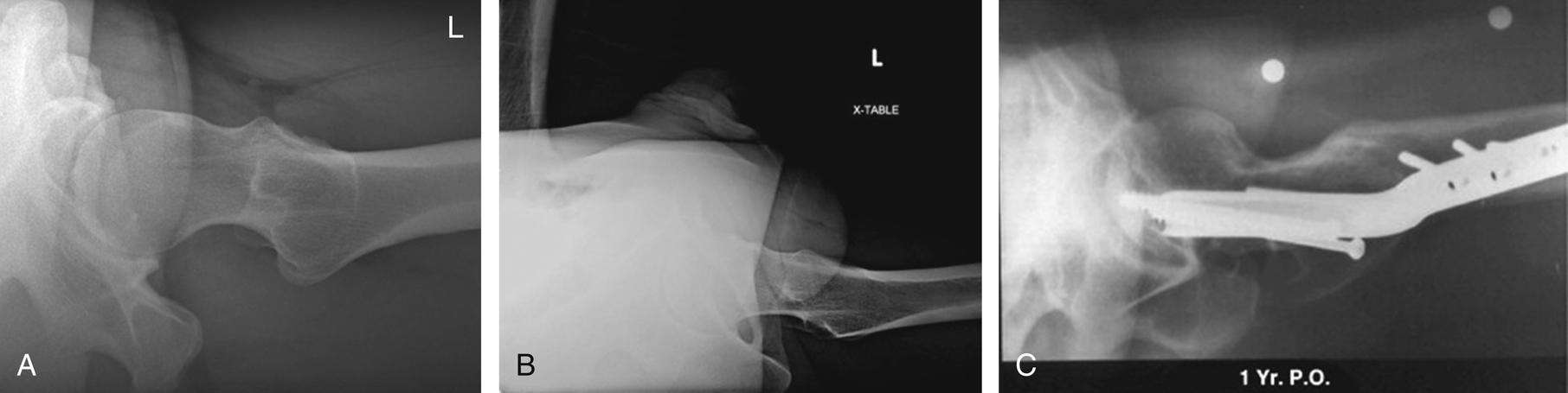
A from McQuillen Martensen K. Radiographic image analysis, ed 4, St. Louis, 2015, Saunders Elsevier; C from Dachs R et al. Double pathology, sarcoidosis associated with multiple myeloma: a case report. Journal of Bone Oncology 3(2):61–65.
A from Berry DJ. Surgery of the hip, ed 2, Philadelphia, 2020, Elsevier; B from Magee DJ. Orthopedic physical assessment, ed 6, Philadelphia, 2014, Saunders; C from Berry DJ. Surgery of the hip, Philadelphia, 2013, Saunders.
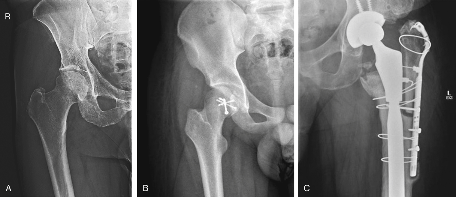
B from Ying LJ. A case of pathological fracture caused by vitamin D insufficiency in a young athlete and a review of the literature. Journal of Clinical Orthopaedics and Trauma 10(6):1111–1115 C From Berry DJ. Surgery of the hip, ed 2, Philadelphia, 2020, Elsevier.