Chapter 8: Cervical and Thoracic Spine
Contributions By Patti Ward, PhD, RT(R), Contributors To Past Editions Alex Backus, MS, RT(R), April Apple, RT(R), and Donna L. Wright, EdD, RT(R)
Radiographic Anatomy
Vertebral Column
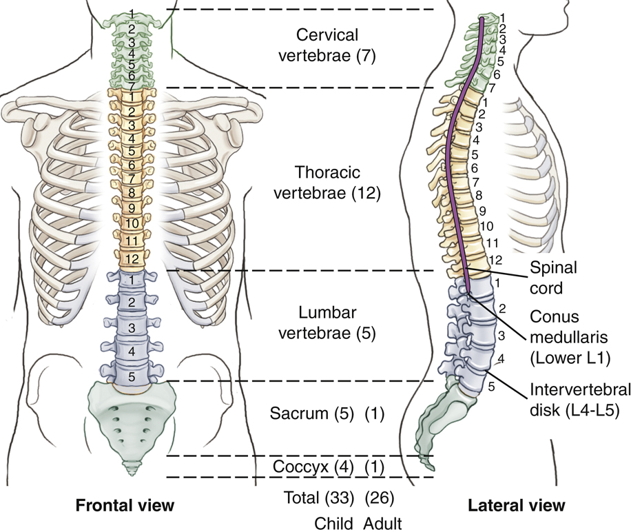
The vertebral (ver′-te-bral) column, commonly called the spine or spinal column, is a complex succession of many bones called vertebrae (ver′-te-bre) (singular is vertebra [ver′-te-brah]) (Fig. 8.1). It provides a flexible supporting column for the trunk and head and also transmits the weight of the trunk and upper body to the lower limbs. This column is located in the midsagittal plane, forming the posterior or dorsal aspect of the bony trunk of the body. As adjacent vertebrae are stacked vertically, openings in each vertebra line up to create a tubelike, vertical spinal canal.
Spinal Canal
The spinal canal, which follows the various curves of the spinal column, begins at the base of the skull and extends distally into the sacrum. This canal contains the spinal cord and is filled with cerebrospinal fluid.
Spinal Cord
The spinal cord, which is enclosed and protected by the spinal canal, begins below the medulla oblongata (me-dul′-ah ob″-long-ga′-tah) of the brain, which passes through the foramen magnum of the skull. The spinal cord continues through the first cervical vertebra all the way down to the lower border of the first lumbar vertebra, where it tapers off to a point called the conus medullaris (ko′-nus med″-u-lar′-is).
NOTE: In some persons, the conus medullaris may extend to as low as the body of L2. Therefore, to avoid striking the spinal cord, the most common site for a lumbar puncture into the spinal canal is at the level of L3–L4. (See myelogram procedure description on p. 310.)
Intervertebral Disks
Tough fibrocartilaginous disks separate typical adult vertebrae. These cushion-like disks are tightly bound to the vertebrae for spinal stability, but allow for flexibility and movement of the vertebral column.
Sections Of Vertebral Column
The vertebral column is divided into five sections. Within each of these five sections the vertebrae have distinctive characteristics.
Detailed anatomy and positioning of the first two sections, the cervical and thoracic vertebrae, are covered in this chapter. The last three sections, the lumbar vertebrae, sacrum, and coccyx, are covered in Chapter 9.
Cervical Vertebrae
The first seven vertebrae are known as cervical vertebrae. Although slight variation may be noted in the height of each vertebra among individuals, the average person has seven cervical vertebrae.
Thoracic Vertebrae
The next 12 vertebrae are the thoracic vertebrae, and each of these connects to a pair of ribs. Because all vertebrae are posterior or dorsal in the body, the term thoracic is more correct for describing this region than the older term, dorsal spine.
Lumbar Vertebrae
The largest individual vertebrae are the five lumbar vertebrae. These vertebrae are the strongest in the vertebral column because the load of body weight increases toward the inferior end of the column. For this reason, the cartilaginous disks between the inferior lumbar vertebrae are common sites of injury and pathology.
Sacrum and Coccyx
The sacrum (sa′-krum) and coccyx (kok′-siks) develop as multiple separate bones and then fuse into two distinct bones. A newborn has five sacral (sa′-kral) segments and from three to five (average, four) coccygeal (kok-sij′-e-al) segments, for an average of 33 separate bones in the vertebral column of a young child. After fusion into a single sacrum and a single coccyx, the adult vertebral column is composed of an average of 26 separate bones.
Vertebral Column Curvatures
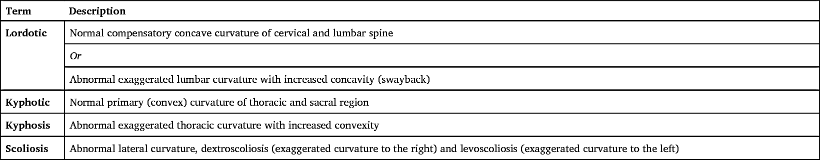
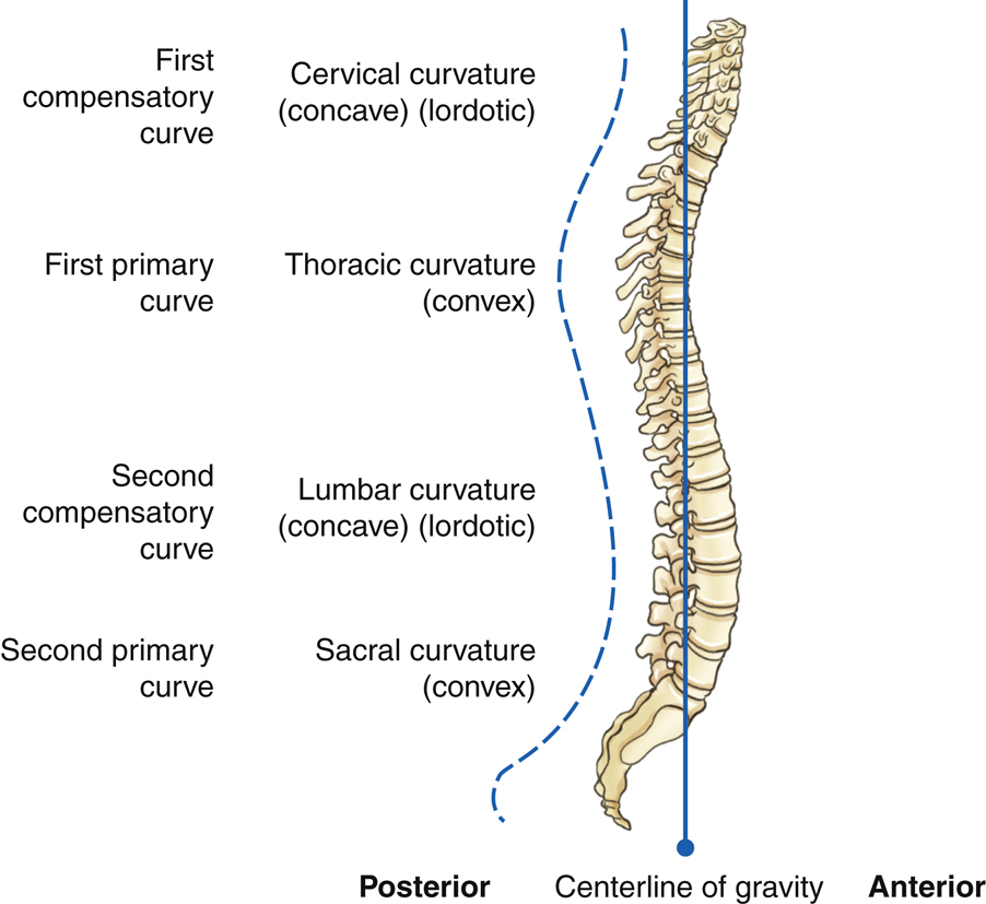
The vertebral column is composed of a series of anteroposterior (AP) curves (Fig. 8.2). The terms concave (a rounded inward or depressed surface like a cave) and convex (a rounded outward or elevated surface) are used to describe these curves. However, the curves are described as opposite, depending on whether one is describing them from an anterior perspective or a posterior perspective. For the purposes of this text, the curves are described as if the patient is being evaluated from the posterior perspective. The cervical and lumbar regions have concave curvatures and are described as lordotic. The thoracic and sacral regions have convex curvatures and are described as kyphotic.
Soon after birth, the thoracic and sacral (pelvic) curves begin to develop. These two convex curves are called primary curves. As children begin to raise their heads and sit up, the first compensatory concave curve forms in the cervical region. The second compensatory concave curve, the lumbar curvature, develops when children learn to walk. Both of the inferior curves, lumbar and sacral (pelvic), are usually more pronounced in women than in men.
These primary and compensatory curvatures are normal and serve an important function by increasing the strength of the vertebral column and helping maintain balance along a center line of gravity in the upright position.
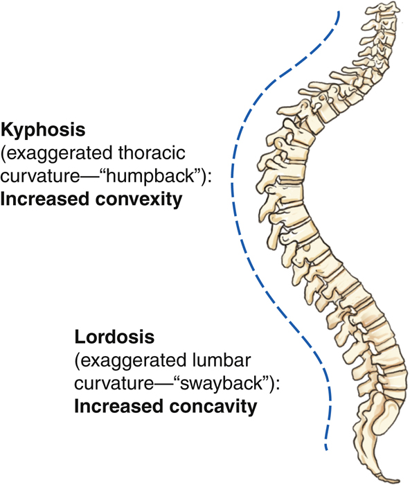
Certain terms are commonly used to describe these curvatures when they become exaggerated or abnormal. These terms, lordosis, kyphosis, and scoliosis, are described as follows.
Lordosis
Kyphosis
Scoliosis
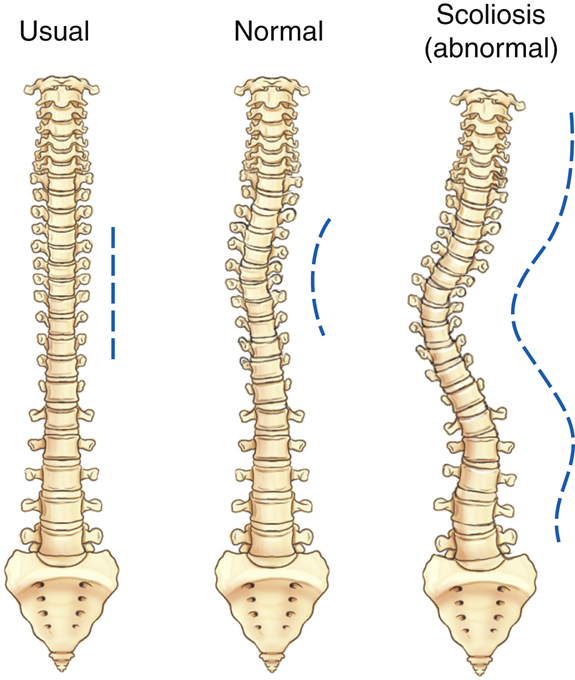
If the spine is viewed from the posterior or anterior perspective (Fig. 8.4), the vertebral column usually is almost straight, with little lateral curvature. Occasionally, a slight lateral curvature occurs in the upper thoracic region of a healthy adult. This curvature usually is associated with the dominant extremity, so this curvature may be convex to the right in a right-handed person and convex to the left in a left-handed person.
An abnormal or exaggerated lateral curvature of the spine is called scoliosis (sko″-le-o′-sis).
1
Dextroscoliosis is an exaggerated curvature to the right, whereas levoscoliosis is an exaggerated curvature to the left. This is a more serious type of problem that occurs when a pronounced S-shaped lateral curvature exists. It may cause severe deformity of the entire thoracic and/or lumbar regions of the spine. The effect of scoliosis is more obvious if it occurs in the lower vertebral column, where it may create tilting of the pelvis with a resultant effect on the lower limbs, producing a limp or uneven walk. Table 8.1 presents a summary of spinal curvature terms.
TABLE 8.1
Typical Vertebral Anatomy
Although the vertebrae in different regions vary in size and shape, all are similar in basic structure. A typical vertebra consists of two main parts, the body and the vertebral arch.
Body
The body is the thick, weight-bearing anterior part of the vertebra. Its superior and inferior surfaces are flat and rough for attachment of the intervertebral disks.
Vertebral Arch
The second part of a typical vertebra consists of a ring or arch of bone that extends posteriorly from the vertebral body. The posterior surface of the body and arch form a circular opening, the vertebral foramen, which contains the spinal cord. When several vertebrae are stacked, as they are in the normal articulated vertebral column, the succession of vertebral foramina forms a tubelike opening, called the vertebral (spinal) canal, which encloses and protects the spinal cord (Fig. 8.5).
Superior Perspective
Fig. 8.6 illustrates the various parts of the vertebral arch. Pedicles (ped′-i-kuls), which extend posteriorly from either side of the vertebral body, form most of the sides of the vertebral arch.
The posterior part of the vertebral arch is formed by two somewhat flat layers of bone called laminae (la-mǝ-nē). Each lamina (la-mǝ-nǝ) extends posteriorly from each pedicle to unite in the midline.
Extending laterally from approximately the junction of each pedicle and lamina is a projection termed the
transverse process.
The spinous process extends posteriorly at the midline junction of the two laminae. The spinous processes, the most posterior extensions of the vertebrae, often can be palpated along the posterior surface of the neck and back.
Lateral Perspective
Fig. 8.7 illustrates a lateral orientation to the typical vertebra. The anterior vertebral body and posterior spinous process are readily identified. Extending posteriorly, directly from the vertebral body on each side, are the pedicles, which terminate in the area of the transverse process. Continuing posteriorly from the origin of the transverse process on each side are the two laminae, which end at the spinous process.
Additional obvious parts seen on this lateral view are the right and left superimposed superior articular processes and the lower pair of the right and left inferior articular processes. These processes allow for certain important joints that are unique and that must be visualized radiographically for each section of the vertebral column, as described on the following pages.
Summary
The typical vertebra consists of two pedicles and two laminae that form the vertebral arch and the vertebral foramen containing the spinal cord, two transverse processes extending laterally, one spinous process extending posteriorly, and the large anterior body. Each typical vertebra also has four articular processes, two superior and two inferior, which comprise the important joints of the vertebral column.


Joints In The Vertebral Column
In addition to the body and the vertebral arch, the joints are a third important aspect of the vertebral column. The vertebral column would be rigidly immovable without the intervertebral disks and the zygapophyseal joints. Respiration could not occur without the spine, which serves as a pivot point for arch-like movement of the ribs.
Intervertebral Joints
The intervertebral joints are amphiarthrodial joints that are found between the vertebral bodies. The intervertebral disks located in these joints are tightly bound to adjacent vertebral bodies for spinal stability, but they also allow for flexibility and movement of the vertebral column.
Zygapophyseal Joints
The four articular processes described on the preceding page are seen projecting from the area of the junction of the pedicles and laminae (Fig. 8.8). The term facet (fas′-et) sometimes is used interchangeably with the term zygapophyseal joint, but the facet is actually only the articulating surface instead of the entire superior or inferior articular process. Zygapophyseal joints were once called by the older term apophyseal joints.
Costal Joints
Although not directly involved in the stability of the spinal column itself, a third type of joint is located along a portion of the vertebral column. In the thoracic region, the 12 ribs articulate with the transverse processes and vertebral bodies. These articulations of the ribs to the thoracic vertebrae, referred to as costal joints, are illustrated in later drawings of the thoracic vertebrae.
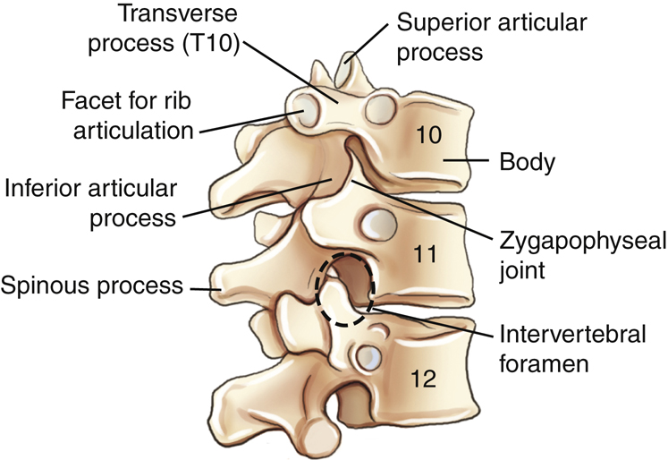
Intervertebral Foramina
The fourth aspect of the vertebral column that is important radiographically involves the intervertebral foramina. Along the upper surface of each pedicle is a half-moon–shaped area termed the superior vertebral notch, and along the lower surface of each pedicle is another half-moon–shaped area called the inferior vertebral notch (see Fig. 8.8). When vertebrae are stacked, the superior and inferior vertebral notches line up. These two half-moon-shaped areas form a single opening, the intervertebral foramen (Fig. 8.9). Therefore, between every two vertebrae are two intervertebral foramina, one on each side, through which important spinal nerves and blood vessels pass.
The zygapophyseal joints and intervertebral foramina must be demonstrated radiographically by the appropriate projection in each of the three major portions of the vertebral column, as described and illustrated in later sections.
Intervertebral Disk
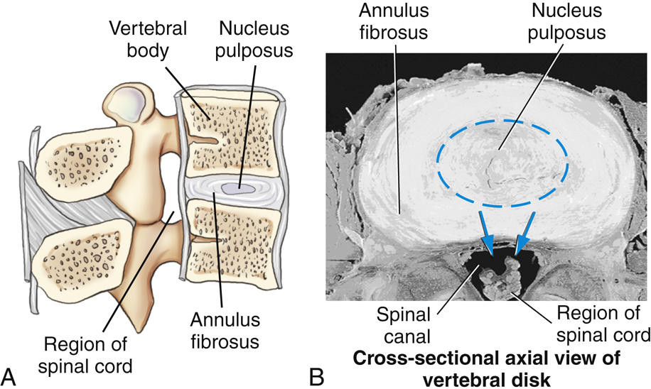
The fifth and final aspect of the vertebral column that is important radiographically consists of the intervertebral disks. Typical adult vertebrae are separated by tough fibrocartilaginous disks between the bodies of every two vertebrae, except between the first and second cervical vertebrae. (The first cervical vertebra has no body.) These fibrocartilage disks provide a resilient cushion between vertebrae, helping to absorb shock during movement of the spine.
As labeled in Fig. 8.10, each disk consists of an outer fibrous portion termed the annulus fibrosus (an′-u-lus) and a soft, semigelatinous inner part termed the nucleus pulposus (nu′-kle-us pul-po′-sus). When this soft inner part protrudes through the outer fibrous layer, it presses on the spinal cord and causes severe pain and numbness that radiates into the upper or lower limbs. This condition, also known as a slipped disk, is termed the herniated nucleus pulposus (HNP) (see Clinical Indications, p. 311).


Characteristics of Cervical Vertebrae
The cervical vertebrae show little resemblance to the lumbar or thoracic vertebrae, which are more typical in appearance. Although most of the parts that form typical vertebrae are present, various cervical vertebrae have unique characteristics such as transverse foramina, bifid spinous process tips, and overlapping vertebral bodies. Each cervical vertebra and vertebral body continues to get larger, progressing down to the seventh cervical vertebra.
C1 (the atlas) and C2 (the axis) are unusual and will be described separately. The third through sixth cervical vertebrae are typical cervical vertebrae. The last, or seventh, cervical vertebra, the vertebra prominens, has many features of thoracic vertebrae, including an extra long and more horizontal spinous process that can be palpated at the base of the neck. This palpable bony landmark is useful for radiographic positioning (Fig. 8.11).
Superior Perspective
Fig. 8.12 shows a typical cervical vertebra (C3 to C6) as viewed from above. The transverse processes are small and arise from both the pedicle and the body, rather than from the pedicle-lamina junction. The hole in each transverse process is called a transverse foramen. The vertebral artery and veins and certain nerves pass through these successive transverse foramina. Therefore, one unique characteristic of all cervical vertebrae is that each has three foramina that run vertically, the right and left transverse foramina and the single large vertebral foramen.
The spinous processes of C2 through C6 are fairly short and end in double-pointed or bifid tips, a second unique characteristic typical of cervical vertebrae.
Lateral Perspective
When viewed from the lateral perspective, typical (C3 to C6) cervical vertebral bodies are small and oblong in shape, with the anterior edge slightly more inferior, which causes slight overlapping of vertebral bodies (Fig. 8.13).
Located behind the transverse process at the junction of the pedicle and lamina are the cervical articular processes. Between the superior and inferior articular processes is a short column (pillar) of bone that is more supportive than the similar area in the rest of the spinal column. This column of bone is called the articular pillar; it sometimes is called the lateral mass when one is referring to C1.
Cervical Zygapophyseal Joints
The superior and inferior articular processes, located over and under the articular pillars, are directly lateral to the large vertebral foramen. The zygapophyseal joints of the second through seventh cervical vertebrae are located at right angles, or 90°, to the midsagittal plane and thus are visualized only in a true lateral position (Fig. 8.14). However, in contrast to the other cervical zygapophyseal joints, those between C1 and C2 (atlantoaxial joints) are visualized only on an AP open mouth projection (see Fig. 8.18).
Cervical Intervertebral Foramina
The intervertebral foramina can be identified by the pedicles, which form the superior and inferior boundaries of these foramina, as shown in Figs. 8.12 and 8.14. The intervertebral foramina are situated at a 45° angle to the midsagittal plane, open anteriorly, as shown on the drawings. They also are directed at a 15° to 20° inferior angle because of shape and overlapping of the cervical vertebrae. Therefore, to open and demonstrate the cervical intervertebral foramina radiographically, a 45° oblique position combined with a 15° to 20° cephalad angle of the x-ray beam would be required (see Figs. 8.31 and 8.33).


Atlas (C1)
The first cervical vertebra, the atlas, a name derived from the Greek god who bore the world on his shoulders, least resembles a typical vertebra. Anteriorly, there is no body but simply a thick arch of bone called the anterior arch, which includes a small anterior tubercle.
The odontoid process or dens is part of the second cervical vertebra but a superior perspective of C1 shows its location and how it is held in place by the transverse atlantal ligament (
Fig. 8.15
). The positional relationship of C1 and C2 is illustrated in Fig. 8.17 and radiographically in Fig. 8.18.
Rather than the two laminae and a spinous process found in typical vertebrae, C1 has a posterior arch that generally bears a small posterior tubercle at the midline (see Fig. 8.15).
Each of the left and right C1 superior articular processes presents a large depressed surface called a superior facet for articulation with the respective left and right occipital condyles of the skull. These articulations, between C1 and the occipital condyles of the skull, are called atlantooccipital joints. The transverse processes of C1 are smaller but still contain the transverse foramina distinctive of all cervical vertebrae.
The articular pillars, the segments of bone between the superior and inferior articular processes, are called lateral masses for C1. Because the lateral masses of C1 support the weight of the head and assist in rotation of the head, these portions are the most bulky and solid parts of C1.
Axis (C2)
The most distinctive feature of the second cervical vertebra, the axis, is the clinically important odontoid process or dens, the conical process that projects up from the superior surface of the body (
Fig. 8.16
). Embryologically, the odontoid process is actually the body of C1, but it fuses to C2 during development. Therefore, it is considered part of C2 in mature skeletons.
Rotation of the head primarily occurs between C1 and C2, with the odontoid process acting as a pivot. The superior facets of the superior articular processes that articulate with the skull also assist in rotation of the head.
Severe stress as the possible result of a forced flexion-hyperextension, the so-called whiplash type of injury, may cause fracture of the dens. Any fracture of the vertebral column at this level could result in serious damage to the spinal cord as well.
The inferior articular process for articulation with C3 lies inferior to the lamina (Fig. 8.16). Below and lateral to the superior articular process is the transverse process, with its transverse foramen. The blunt spinous process with its bifid tip extends posteriorly.
Relationship Of C1 And C2
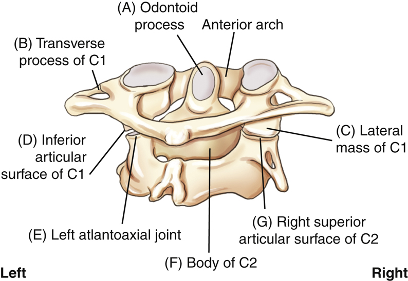
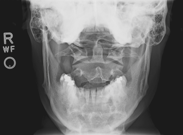
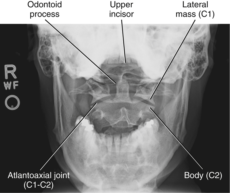
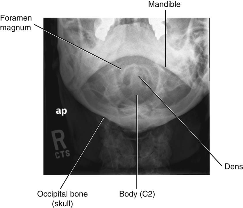
Radiographic demonstration of the relationship of C1 to C2 and the relationship of C1 to the base of the skull is clinically important because injury this high in the spinal canal can result in serious paralysis and death. Fig. 8.18 shows the radiographic image of an AP projection taken through an open mouth to demonstrate C1 and C2. The anterior arch of C1, which lies in front of the dens, is not clearly visible on this image because it is a fairly thin piece of bone compared with the larger denser dens.
Articulations between C2 and C1, the atlantoaxial joints, are normally symmetric, and so the relationship of the odontoid process to C1 also must be perfectly symmetric. Both injury and improper positioning can render these areas asymmetric. For example, rotation of the skull can alter the symmetry of these spaces and joints, thus imitating an injury. The median atlantoaxial joint is a pivot joint located between the odontoid process, anterior arch of C1, and the transverse atlantal ligament. Therefore, accurate positioning for this region is essential. The structures labeled on Fig. 8.17 correspond to the letters on Fig. 8.18 as follows:


Characteristics of Thoracic Vertebrae
An overview of the 12 thoracic vertebrae reveals marked progressive differences in the size and appearance of upper vertebrae compared with lower ones, as demonstrated in Fig. 8.19.
T5, T6, T7, and T8 are considered typical thoracic vertebrae. The upper four thoracic vertebrae are smaller and share features of the cervical vertebrae. The lower four thoracic vertebrae are larger and share characteristics of the lumbar vertebrae.
Rib Articulations
A key distinguishing feature of all 12 thoracic vertebrae is their facets for articulation with ribs. Each thoracic vertebra is associated closely with one pair of ribs. Fig. 8.20 shows that the two lumbar vertebrae, L1 and L2, do not have facets for rib articulations.
Costovertebral Joints
Each thoracic vertebra has a full facet (fas′-et) or two partial facets, called demifacets (dem′-e-fas′-ets), on each side of the body. Each facet or combination of two demifacets accepts the head of a rib to form a costovertebral joint (Figs. 8.19 to 8.21).
Vertebrae with two demifacets share articulations with the heads of ribs. For example, the head of the fourth rib straddles or articulates with demifacets on the vertebral bodies of both T3 and T4. The superior portion of the rib head articulates with the demifacet on the inferior margin of T3, and the inferior portion of the rib head articulates with the demifacet on the superior margin of T4.
Identifying ribs and the thoracic vertebrae is an important radiographic skill. T1 has a full facet and a demifacet on its inferior margin. T2 through T8 have demifacets on their upper and lower margins. T9 has only one demifacet on its upper margin. T10 through T12 have full facets. Knowing the facet arrangement makes it easy to predict the rib distribution. Rib 1 articulates with T1 only, rib 2 articulates with T1 and T2, and so forth. Ribs 11 and 12 articulate only with T11 and T12.
Costotransverse Joints
In addition to costovertebral joints, all of the first 10 thoracic vertebrae also have facets (one on each transverse process) that articulate with the tubercles of ribs 1 through 10. These articulations are termed costotransverse joints.
Note in Figs. 8.19 and 8.20 that T11 and T12 do not show facets at the ends of the transverse process for rib articulations. Thus, as the first 10 pairs of ribs arch posteriorly from the upper 10 vertebral bodies, the tubercle of each rib articulates with one transverse process to form a costotransverse joint. Ribs 11 and 12, however, articulate only at the costovertebral joints.
The superior cross-sectional perspective of typical rib articulations (Fig. 8.21) shows that the articulations are closely spaced and are enclosed in synovial capsules. These synovial joints are diarthrodial and allow slight gliding movements. This anatomy is further demonstrated and described in Chapter 10.
Superior and Lateral Perspectives
Note the normal anatomic structures of a typical vertebra (vertebral body, pedicles, intervertebral foramina, superior and inferior articular processes, laminae, transverse processes, spinous processes). A unique characteristic of the thoracic region is that the long spinous process is projected so far inferiorly, as seen on a lateral view (Fig. 8.22). For example, on an AP radiographic projection of the thoracic spine, the spinous process of T4 will be superimposed on the body of T5.
Lateral Oblique Perspective
The superior articular processes (facing primarily posteriorly) and the inferior articular processes (facing more anteriorly) are shown to connect the successive thoracic vertebrae to form the zygapophyseal (apophyseal) joints.
On each side, between any thoracic vertebrae, are intervertebral foramina, which are defined on the superior and inferior margins by the pedicles (Fig. 8.23).


Thoracic Zygapophyseal Joints
The structure and angles of the facets of the inferior and superior articular processes making up the zygapophyseal joints differ markedly from those of the cervical and lumbar vertebrae. In the thoracic vertebrae, the zygapophyseal joints form an angle of 70° to 75° from the midsagittal plane (MSP). Therefore, for example, to open and demonstrate the thoracic zygapophyseal joints radiographically, a 70° to 75° oblique position with a perpendicular central ray is required.
Thoracic Intervertebral Foramina
As demonstrated in Fig. 8.24, the openings of the intervertebral foramina on the thoracic vertebrae are located at right angles, or 90°, to the midsagittal plane. This is best demonstrated again in Fig. 8.34, a photograph of the thoracic portion of a skeleton in a lateral position. See Fig. 8.36 for a radiographic image of the same lateral position. Both figures clearly show the left and right thoracic intervertebral foramina superimposed on each other.
Unique C1–C2 Joint Classifications
Table 8.2 lists the three joints or articulations with two different movement types involved between the C1 and C2 vertebrae. The first two joints are the right and left lateral atlantoaxial joints between the inferior articular surface of C1 (atlas) and superior articular surface of C2 (axis). These are classified as synovial joints with diarthrodial, or freely movable, plane (or gliding) movements (see Figs. 8.17 and 8.18).
The third joint between C1 and C2 is the medial atlantoaxial joint. This articulation is located between the odontoid process of C2 and the anterior arch of C1 and is held in place by the transverse atlantal ligament, allowing a pivotal rotational movement between these two vertebrae. Therefore, this joint or articulation also is classified as a synovial joint that is freely movable, or diarthrodial, with a pivot, or trochoid, type of movement (see Figs. 8.15 and 8.17).
TABLE 8.2
| Joints | Classification | Mobility Type | Movement Type |
|---|---|---|---|
| Skull–C1 | |||
| Atlanto-occipital | Synovial | Diarthrodial | Ellipsoid (condyloid) |
| C1–C2 | |||
| R and L lateral atlantoaxial (2) a | Synovial | Diarthrodial | Plane (gliding) |
| Median atlantoaxial (1) b | Synovial | Diarthrodial | Pivot (trochoid) |
| C2–T12 | |||
| Intervertebral | Cartilaginous (symphysis) | Amphiarthrodial (slightly movable) | N/A |
| Zygapophyseal | Synovial | Diarthrodial | Plane (gliding) |
| T1–T12 | |||
| Costovertebral | Synovial | Diarthrodial | Plane (gliding) |
| T1–T10 | |||
| Costotransverse | Synovial | Diarthrodial | Plane (gliding) |


Anatomy Review with Radiographic Images
Ap Cervical Spine Image
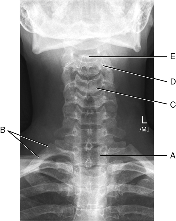
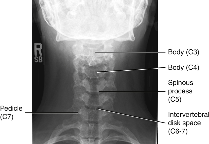
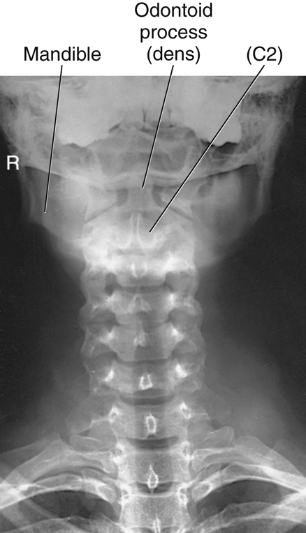
Fig. 8.25 shows a conventional AP radiographic image of the cervical spine. Usually, the first two or three thoracic vertebrae, as well as C3 to C7, are seen well on this projection. Identifying specific cervical vertebrae is possible by starting with T1, which can be identified by the attachment of the first pair of ribs. Therefore, to localize T1, locate the most superior ribs and find the vertebra to which they appear to connect. After T1 is located, visible cervical vertebrae can be identified by starting at C7 and counting upward.
On Fig. 8.25:
NOTE: The white area at the top of the radiograph is created by the combined shadows of the base of the skull and mandible. These structures effectively obscure the first two cervical vertebrae on this type of radiograph.
Lateral Cervical Spine Image
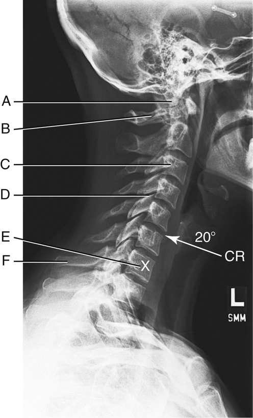
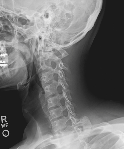
The single most important radiograph clinically for a cervical spine series is a well-positioned lateral, such as the one illustrated in Fig. 8.26. All seven cervical vertebrae and the alignment with T1 should be demonstrated on any lateral cervical spine radiograph. This is difficult in patients with thick, muscular, or wide shoulders and short necks. Additional projections may be necessary to supplement the routine lateral image. C1 and C7 have distinctive posterior structures that make it easier to identify them on radiographic images. The tubercle on the posterior arch of C1 resembles a spinous process and is easily identified. The spinous process of C7 is long and prominent, making it also easy to identify.
Fig. 8.26 shows that the lower anterior margins of the last four or five cervical vertebral bodies have a slightly lipped appearance. This characteristic, along with the general shape of the cervical vertebral bodies, requires that the central ray (CR) be angled approximately 15° to 20° cephalad (toward the head) to open up these lower intervertebral spaces during an AP cervical spine projection:
- A. Odontoid process (dens) extending up through the anterior arch of C1
- B. Posterior arch of the atlas, C1
- C. Body of C3
- D. Zygapophyseal joint between C4 and C5 (best shown on a lateral projection for the cervical spine)
- E. Body of C7
- F. Spinous process of C7, vertebra prominens (a positioning landmark)
Oblique (Rpo) Cervical Spine Image
Fig. 8.27 illustrates how well the oblique position demonstrates the cervical intervertebral foramina. Spinal nerves to and from the cord are transmitted through these intervertebral foramina.

Ap and Lateral Thoracic Spine Image
Individual thoracic vertebrae can best be identified on the AP projection through visual cues provided by the posterior rib articulations. The first rib has a distinctive sharp curvature and attaches to T1. The twelfth rib is very short and attaches to T12. After identifying T1 or T12, one can count superiorly or inferiorly to identify the other thoracic vertebrae.
AP Thoracic Spine Image (Fig. 8.28)
- A. First posterior rib
- B. Tenth posterior rib
- C. Spinous process of T11, faintly seen on edge through body
- D. Body of T12
- E. Intervertebral disk space between T8 and T9
- F. Body of T7 (center of T spine and of average chest)
- G. Body of T1 (Remember, heads of first ribs articulate with upper portion of T1)
Lateral Thoracic Spine (Fig. 8.29)
Table 8.3 presents a summary of distinguishing features of the cervical and thoracic spine.
TABLE 8.3


Intervertebral Foramina Versus Zygapophyseal Joints
Two anatomic areas of the spine that generally need to be demonstrated by the proper radiographs are the intervertebral foramina and zygapophyseal joints. This is especially important for the cervical spine. The physician gains important information concerning the relationship of consecutive vertebrae by studying these two areas on the appropriate radiograph. To complicate matters, however, depending on the part of the spine to be radiographed (cervical, thoracic, or lumbar), a different body position is required to show each anatomic area best.
Cervical Spine Skeleton
Two photographs of the cervical vertebrae (Figs. 8.30 and 8.31) are shown in position to visualize these areas on the cervical vertebrae. Fig. 8.30 is a cervical section of the vertebral column in a left lateral position, and Fig. 8.31 is a 45° LPO position. The zygapophyseal joints visualize well in the lateral position (see arrow).
On the right, the posterior oblique with a 45° rotation shows that the intervertebral foramina are clearly opened (see arrow). It is important to know that the LPO position opens up the foramina on the right side and a 15° to 20° CR cephalad angle is needed. Therefore, on a posterior oblique cervical spine radiograph, the upside (side farthest from IR) is the side on which the intervertebral foramina are opened well. If this were taken in an anterior oblique position, with the foramina closest to the image receptor (IR), the downside would be open and a 15° to 20° caudad angle would be required.
Cervical Spine Radiographs
The two radiographs of the cervical spine (Figs. 8.32 and 8.33) illustrate the same anatomy in the same two positions as shown on the skeleton above. The lateral position on the right best shows the zygapophyseal joints. The joint on each side is superimposed on the joint on the opposite side. It is important to remember that the zygapophyseal joints are located between the articular pillars of each vertebra.
The oblique cervical spine radiograph shows the circular intervertebral foramina opened. In each oblique radiograph, only one set of foramina are opened, whereas the ones on the opposite side are closed. Because this position is an LPO, the right intervertebral foramina or those on the upside are being shown.
Remember that the LPO will show the same anatomy as the right anterior oblique (RAO). Therefore, if the patient were placed in an anterior oblique position, the downside foramina to the IR would be shown. Thus, in either case, LPO or RAO, the right intervertebral foramina will be visualized.
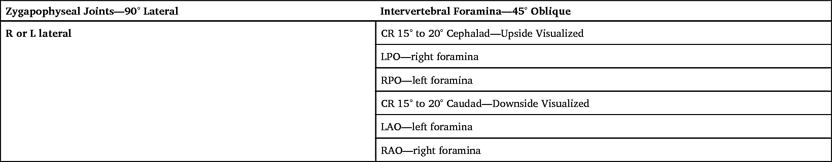
Table 8.4 presents a summary of cervical spine joints and foramina.
TABLE 8.4


Thoracic Spine Skeleton
Two photographs of the thoracic vertebrae are shown in Figs. 8.34 and 8.35. The thoracic vertebrae on the left are in a lateral position; those on the right are in an oblique position. The lateral position of the thoracic spine best shows the intervertebral foramina. A 70° oblique is necessary to open up the zygapophyseal joints on the thoracic spine.
The posterior oblique position on the right shows the zygapophyseal joint on the upside. Anterior oblique would demonstrate the downside joints.
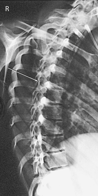
Thoracic Spine Radiographs
Radiographs of the thoracic spine in the lateral position and in the 70° oblique position (Figs. 8.36 and 8.37) correspond to the position of the thoracic skeleton directly above. Observe that the round openings of the superimposed intervertebral foramina are best visualized on the lateral radiograph on the left (see arrow).
The zygapophyseal joints are best visualized on the oblique radiograph on the right. The oblique radiograph is in a 70° LPO position, which should best visualize the zygapophyseal joints on the upside, or those farthest away from the IR. The LPO position best shows the right zygapophyseal joints.
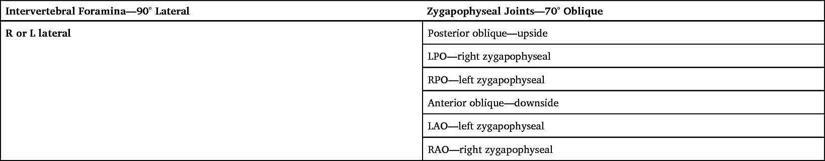
If the oblique was taken as anterior oblique, the opposite would be true and the downside joints would be demonstrated. A left anterior oblique would demonstrate the left zygapophyseal joints. Therefore, an LAO would show the same zygapophyseal joints as an RPO, as seen in Table 8.5.
TABLE 8.5


Radiographic Positioning
Topographic Landmarks
Topographic landmarks are useful, palpable reference points for radiographic positioning that may be helpful when well-collimated radiographic images of specific vertebrae are required. Variations are seen among patients of different body habitus, but these landmarks show the anatomic relationships of an average patient.
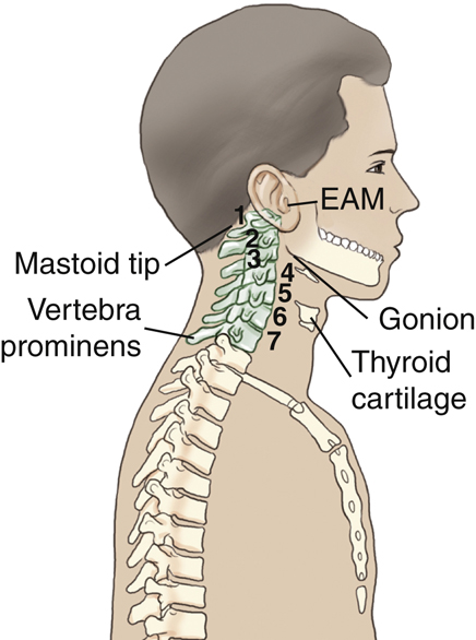
Cervical Landmarks
Various anatomy correlates with levels of the cervical spine, as illustrated in Figs. 8.38 and 8.39. The mastoid process (tip) corresponds to the level of C1. Another way to localize the level of C1 is to go about 1 inch (2.5 cm) below the level of the external auditory meatus (EAM).
With the head in a neutral position, the angle of the mandible or gonion, is at the same level as C3. The most prominent part of the thyroid cartilage, or Adam’s apple, is at the approximate level of C5. This thyroid cartilage landmark varies between the levels of C4 and C6.
The spinous process of the last cervical vertebra, C7 vertebra prominens, is at about the same level as the body of T1. It is more obvious with the patient’s head tipped forward and should be used to help locate C7 and T1 rather than the top of the shoulders (too much variability exists in the position of shoulders because of relative fitness and posture). This is a useful landmark because of the importance of including all of C7 on a lateral cervical radiograph.
The shoulders should be depressed as much as possible for a lateral C spine radiograph; however, depending on the patient’s body habitus, the shoulders may still occasionally superimpose the last cervical vertebra. Additional images may be necessary to demonstrate the alignment of C7 to T1 when the shoulders are too dense for adequate penetration on a routine lateral. In this case, the jugular notch or the vertebra prominens can be used as a landmark for centering.
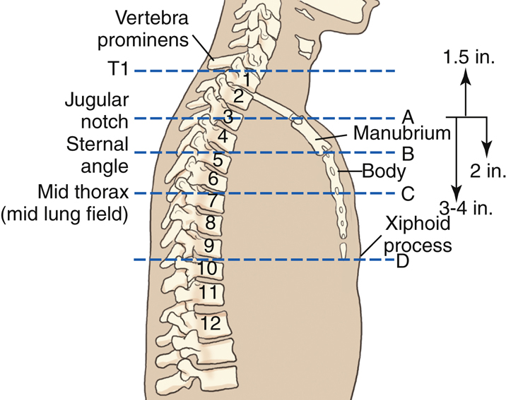
Sternum And Thoracic Spine Landmarks
Sternum anatomy correlates with levels of the thoracic spine, as illustrated in Figs. 8.40 and 8.41. The sternum is divided into three basic sections. The upper section is the manubrium. The easily palpated U-shaped dip in the superior margin is the jugular (suprasternal) notch (A). The jugular notch is at the level of T2 and T3. T1 is about 1.5 inches (4 cm) superior to the level of the jugular notch.
The first thoracic vertebra can be palpated posteriorly at the base of the neck for the prominent spinous process of C7, the vertebra prominens. Note that the long, sloping vertebra prominens extends downward, with its tip at the level of the body of T1.
The central portion of the sternum is called the body. The manubrium and the body connect at a slight, easily located angle termed the sternal angle (B), about 2 inches (5 cm) inferior to the manubrial notch. Posteriorly, this is the level of the junction of T4 and T5. Anteriorly, this is the level of the articulation of the second rib onto the sternum.
A frequently used landmark is the level of T7. Anteriorly, it is located about 3 to 4 inches (8 to 10 cm) inferior to the jugular notch or at the midpoint of the jugular notch and the xiphoid process. Posteriorly, this is about 7 to 8 inches (18 to 20 cm) below the vertebra prominens (C). This landmark indicates the approximate center of the 12 thoracic vertebrae because the inferior vertebrae are larger than the superior ones.
The most inferior end of the sternum is called the xiphoid process, xiphoid tip, or ensiform process. Locating the xiphoid process on a patient requires some pressure (D). The xiphoid tip is at the level of T9–T10.


Positioning and Technical Considerations
Erect Versus Recumbent
Radiographic examinations of the cervical spine generally are made with the patient erect to demonstrate alignment and ligament stability. An erect position also allows the natural curvature of the spine to be demonstrated, the shoulders to be depressed, and a 72-inch (180-cm) source–image receptor distance (SID) to be used for the lateral and oblique projections to improve image quality and reduce magnification.
The patient may be seated or standing in front of an upright bucky or a radiographic table. Some conditions, such as trauma, may require radiography of the cervical spine with the patient in a recumbent position.
Thoracic spines are radiographed in recumbent or erect positions, depending on the preference of the clinical facility. However, scoliosis examinations must be radiographed in the erect position (described in Chapter 9).
Patient Radiation Protection
Exposure to radiosensitive tissues such as the thyroid, parathyroid, breasts, testes, and ovaries can be minimized during radiography of the cervical and thoracic spine by close collimation, the use of proper exposure factors, and minimization of repeats. Theoretically, radiosensitive organs in the thoracic region (e.g., breast, thyroid) should be shielded from radiation, but because of the practicalities of maintaining the shields (e.g., erect positions, flexion-extension views), this is not a common practice when imaging the spinal column, especially for cervical spine projections. However, for radiation dose reduction measures, lead contact shielding over the gonads and other radiosensitive areas is a good practice when it is clinically practical. Also, the thyroid dose can be reduced significantly during cervical and thoracic spine oblique radiography by positioning the patient in an anterior oblique rather than a posterior oblique position (Figs. 8.42 and 8.43).
Technical and Image Quality Factors
For the purposes of this discussion, technical and image quality factors include the following: (1) exposure factors; (2) focal spot size; (3) compensating strategies; (4) SID; (5) scatter reduction; and (6) IR alignment.
During lateral and oblique cervical spinal radiography, the spinal column is unavoidably situated some distance from the IR (increased object–image receptor distance [OID]). Image geometry, therefore, results in reduced spatial resolution caused by magnification of spinal anatomy.
Exposure Factors
The kVp range for a cervical spine is 70 to 85 kVp and, for the thoracic spine, 75 to 90 kVp depending on the imaging system being used. Using higher kVp reduces patient dose, as long as lower mAs values are used.
The lateral thoracic spine image is usually obtained with the use of an orthostatic (breathing) technique to blur structures that overlie the thoracic vertebrae. This breathing technique involves the patient taking shallow breaths during the exposure and requires a minimum of a 3- or 4-second exposure time, with a low mA setting. The technologist must be sure the thorax, in general, is not moving during the exposure other than from the gentle breathing motion.
Focal Spot Size
Use of a small focal spot can improve spatial resolution. Orthostatic techniques require a long exposure time at low mA settings that have smaller focal spot sizes.
Compensating Strategies
The range of vertebral sizes and the different types of surrounding tissues in the thoracic region, in particular, present a radiographic challenge. For example, on an AP image, exposure factors could overexpose the superior end (smaller vertebral bodies surrounded by air-filled lungs) and underexpose the inferior end (larger vertebral bodies surrounded by dense abdominal tissues below the diaphragm).
The anode heel effect may be applied for AP thoracic spine projections by positioning the anode end of the tube (less intense portion of the field) over the thinner anatomic part (superior thoracic spine). However, the use of a compensating filter is generally a more effective method of equalizing density along an AP thoracic spine. See Chapter 1 for more information on compensating filters.
SID
Cervical spine radiographs should be imaged with a minimum of 40 inches (100 cm). An increased SID of 60 to 72 inches (150 to 180 cm) should be used for lateral, cervicothoracic (“swimmer’s”) and oblique projections to compensate for the increased OID.


Scatter Radiation
Use of higher kVp in thick or dense tissue results in increased production of scatter radiation, which degrades the radiographic image. The effects of scatter radiation can be minimized in three ways: (1) with close collimation; (2) with a lead blocker placed on the tabletop next to the patient during lateral radiography (Fig. 8.44); and (3) with grids. Collimation reduces the amount of scatter produced, and lead blockers and grids prevent scatter radiation from reaching the IR. Manufacturers have created post-processing software for digital systems that will eliminate the presentation of scatter radiation on the image; however, as a post-processing tool, this does not reduce or prevent scatter radiation from reaching the image as to the measures listed above.
Spine radiography requires a grid, with the exception of certain situations. When a patient’s neck measures less than 10 cm, a grid is unnecessary. Placement of the IR far from the spine during lateral cervical radiography creates an air gap which also reduces the amount of scatter radiation that reaches the IR. This increased OID does however contribute to greater magnification of the image, which accounts for an above-mentioned increase in SID to compensate.
Part-IR Alignment
Correct part-IR alignment is important during spine radiography because the beam must pass through specific anatomic structures. For example, this may require placing a radiolucent sponge under the patient’s waist to keep the spine near parallel to the IR during lateral thoracic positioning (see Fig. 8.44).
Optimal object-IR alignment is a challenge for lateral thoracic and lumbar spine radiography because of the wide range of body builds in male and female patients. This is illustrated in the positioning pages for those projections.
Special Patient Considerations
Pediatric Applications
Two primary concerns in pediatric radiography are patient motion and patient radiation dose. A clear explanation of the procedure is required to obtain maximal trust and cooperation from the patient and guardian.
Careful immobilization is important for achieving proper positioning and reducing patient motion. A short exposure time with optimal mA and kVp helps reduce the chance of motion. To reduce dose to the pediatric patient, use optimal kVp.
To ensure safety from falls or other physical injury, continuously watch and care for pediatric patients. Refer to Chapter 16 for detailed communication strategies, immobilization techniques, and explanations.
Geriatric Applications
The physical effects associated with aging may cause the geriatric patient to require additional assistance, time, and patience if the required positions for spinal radiography are to be obtained. Patient care for the geriatric patient should include special attention in the areas of communication, patient safety, and patient handling. These patients may require extra time and assistance in achieving the required position.
Communication
Varying degrees of vision and hearing loss can reduce patient understanding and cooperation. To improve communication, do the following: (1) avoid background noise; (2) face the patient; (3) gain the patient’s attention; and (4) use clear, simple instructions. Allow the patient to retain his or her hearing aids and eyeglasses, if possible, or wait until the last moment if it is necessary to remove them. Use touch to emphasize positioning instructions. For the patient with significant hearing loss, a lowered voice with increased volume improves the likelihood that the patient will hear you. To verify understanding, ask the patient to repeat instructions. Always treat the geriatric patient with dignity and respect.
Safety
The aging process can affect changes in balance and coordination that can bring about dizziness, vertigo, and an increased incidence of falling. Geriatric patients often fear falling. To ensure good patient safety, always assist the patient with the following: (1) to get onto and off the radiographic table; (2) to change position; and (3) to sit down. Reassurance and additional care from the technologist enable the patient to feel more secure and comfortable.
Patient Handling and Comfort
The geriatric patient experiences skin changes and a diminished ability to regulate temperature. As the skin ages, it becomes thinner, is more easily torn, and is more prone to bleeding and bruising. Use special care when holding or moving the patient. Avoid using adhesive tape and use special care when removing tape from skin. Use a radiolucent pad on the examination table to minimize skin damage and to provide comfort and added warmth. Extra blankets may be required to keep the patient warm. The patient with exaggerated kyphosis needs extra pillows under the head or may be more comfortable in the erect position for some procedures.
Technical Factors
Because of the high incidence of osteoporosis in geriatric patients, the kVp and/or mAs may require a decrease if manual exposure factors are being used. Older patients may have tremors or difficulty holding steady. Use of short exposure times (associated with the use of a high mA) is recommended to reduce the risk of motion.
Bariatric Patient Considerations
Bariatric patients may present some challenges when positioning for cervical and thoracic spine images. Additional tissue density from adipose tissue may require an increase in technical factors. An increase in kVp to improve penetration through additionally thick tissue may be necessary. mA and time may also be increased; however, a technologist must always use as low as reasonably achievable (ALARA) recommendations to avoid excessive radiation dose.
Measures must also be taken to reduce scatter radiation exposure to the IR because of the increased amount of tissue. The use of a grid for anatomic structures over 10 cm can be used to reduce the demonstration of scatter. Tight collimation to the anatomy of interest will also help to reduce the amount of scatter radiation reaching the IR. The location of the cervical and thoracic spine anatomy will be aligned similarly in the general population of patients. Use known external landmarks to aid in identifying the beginning and terminal ends of the cervical and thoracic spine regions. The swimmer’s method of demonstrating the C7–T1 junction may be necessary for completion of both lateral cervical and thoracic spine views.
Digital Imaging Considerations
The following guidelines are important for digital imaging of the cervical and thoracic spines:
- 1. Correct centering to allow accurate processing by the image reader
- 2. Close collimation, tabletop lead masking, and use of grids to reduce scatter exposure to the highly sensitive image receptors
- 3. Following the ALARA principle in determining exposure factors, including the highest kVp and the lowest mAs that result in desirable image quality.
- 4. Evaluation of exposure indicator to help verify optimum image quality with the least radiation to the patient.
Alternative Modalities and Procedures
Myelography
Myelography is an alternative radiographic procedure that involves fluoroscopic and radiographic examination of the spinal canal for
evaluation of lesions in the spinal canal, intervertebral disks, or nerve roots. Water-soluble iodinated contrast is injected into the subarachnoid space of the spinal canal at the level of L3–L4. If no obstruction exists, the contrast will flow freely with the cerebrospinal fluid throughout the spinal canal and around nerve roots. Lesions will appear as filling defects.
Magnetic resonance imaging (MRI) and computed tomography (CT) are other modalities of choice for evaluating spinal canal–related symptoms; however radiographic myelography is still being performed in many institutions and is described in greater detail in Chapter 19.
Computed Tomography
CT scans are useful for evaluating spinal trauma such as fractures, subluxations, herniated disks, tumors, and pathologic conditions such as stenosis and arthritis.
Magnetic Resonance Imaging
MRI of the cervical and thoracic spine is especially useful for demonstrating soft tissue (noncalcified) structures associated with the spine, such as the intervertebral disks, ligaments and the spinal cord itself. The MRI midsagittal image of a cervical spine in Fig. 8.45 clearly demonstrates not only bony structure but soft tissue as well. The vertebral canal which contains the spinal cord (Fig. 8.45, label B) is seen as a tubelike column that is directly posterior to the vertebral bodies. The spinal cord is seen to be a continuation of the medulla oblongata of the brain (Fig. 8.45, label A). A herniation of the disk between C6 and C7 is demonstrated by a slight posterior displacement, which causes mild spinal cord displacement.
Nuclear Medicine
NM studies involve the injection of pharmaceuticals tagged with tracer elements to demonstrate specific physiologic processes, including those that affect bone. For example, a technetium phosphate compound is injected and circulates with the blood. It will concentrate in areas of increased bone activity, creating a “hot spot” on the nuclear medicine scan image. (A hot spot is a region of nonsymmetrical uptake of the radioisotope.) Nuclear medicine scans can demonstrate several conditions related to the spine, such as bone tumors, healing fractures, metastases of cancer to the spine, osteomyelitis (bone infections), and additive or degenerative disease processes, such as Paget disease.
Clinical Indications
Clinical indications involving the cervical and thoracic spine that all technologists should be familiar with include the following (not necessarily an inclusive list).
- Clay shoveler’s fracture: This fracture, which results from hyperflexion of the neck, results in avulsion fractures on the spinous processes of C6 through T1. The fracture is best demonstrated on a lateral cervical spine radiograph.
- Compression fracture: Frequently associated with osteoporosis, a compression fracture often involves collapse of a vertebral body, which results from flexion or axial loading most often in the thoracic or lumbar regions. It also can result from severe kyphosis caused by other diseases. The anterior edge collapses, changing the shape of the vertebral body into a wedge instead of a block. This induces kyphosis and may compromise respiratory and cardiac function; it also frequently results in injury to the spinal cord. Compression fractures are best demonstrated on a lateral projection of the affected region of the spine.
- Facets – unilateral subluxation and bilateral locks: Zygapophyseal joints in the cervical region can be disrupted during trauma. If the patient’s injury involves flexion, distraction, and rotation, only one zygapophyseal joint may be out of alignment, with a unilateral subluxation. Radiographically, the vertebral body will be rotated on its axis, creating a bowtie artifact on the lateral cervical spine image. If the patient’s injury involves extreme flexion and distraction, both right and left zygapophyseal joints on the same level can be disrupted, creating bilateral locked facets. Radiographically, the vertebral body will appear to have jumped over the vertebral body immediately inferior to it. In either case, the spine is not stable because the spinal cord is distressed by this manipulation. Following the AP and lateral projections of the cervical spine, CT scanning of the spine generally is indicated.
- Hangman’s fracture: This fracture extends through the pedicles of C2, with or without subluxation of C2 on C3. This cervical fracture occurs when the neck is subjected to extreme hyperextension. The patient is not stable because the intact odontoid process is pressed posteriorly against the brainstem. A lateral projection of the cervical spine will demonstrate the anterior displacement of C2 characteristic of a hangman’s fracture.
- Herniated nucleus pulposus (HNP): If the soft inner part (nucleus pulposus) of an intervertebral disk protrudes through the fibrous cartilage outer layer (annulus) into the spinal canal, it may press on the spinal cord or spinal nerves, causing severe pain and possible numbness that radiate into the extremities. This condition sometimes is called a slipped disk. This is well demonstrated by MRI of the cervical spine region, as seen in Fig. 8.45. Although it can affect cervical vertebrae, HNP more frequently involves levels L4 through L5.
- Jefferson fracture: This comminuted fracture (splintered or crushed at site of impact) occurs as a result of axial loading, such as that produced by landing on one’s head or abruptly on one’s feet. The anterior and posterior arches of C1 are fractured as the skull slams onto the ring. The AP open mouth projection and lateral cervical spine projections will demonstrate a Jefferson fracture.
- Kyphosis: This condition is an abnormal or exaggerated convex curvature of the thoracic spine that results in stooped posture and reduced height. Kyphosis may be caused by compression fractures of the anterior edges of the vertebral bodies in osteoporotic patients, particularly postmenopausal women. It also may be caused by poor posture, rickets, or other diseases involving the spine (see Scheuermann disease). A lateral projection of the spine will best demonstrate the extent of kyphosis.
- Odontoid fracture: This fracture involves the dens and can extend into the lateral masses or arches of C1. An AP open mouth projection will demonstrate any disruption of the arches of C1.
- Osteoarthritis This type of arthritis is characterized by degeneration of one or many joints. In the spine, changes may include bony sclerosis, degeneration of cartilage, and formation of osteophytes (bony outgrowths).
- Osteoporosis: This condition is characterized by loss of bone mass. Bone loss increases with age, immobilization, long-term steroid therapy, and menopause. The condition predisposes individuals to vertebral and hip fractures. Bone densitometry is a relatively low-dose imaging modality for measuring the degree of osteoporosis, as described in Chapter 20.
- Scheuermann disease: A relatively common disease of unknown origin that generally begins during adolescence, Scheuermann disease results in the abnormal spinal curvature of kyphosis and scoliosis. It is more common in males than females. Most cases are mild and continue for several years, after which symptoms disappear but some spinal curvature remains.
- Scoliosis: Although many individuals normally have some slight lateral curvature of the thoracic spine, an abnormal or exaggerated lateral curvature of the spine is called scoliosis. Scoliosis is most common in children between the ages of 10 and 14 years and is more common in females. It may require the use of a back brace for a time, until the condition of vertebral stability improves. This deformity, if severe enough, may complicate cardiac and respiratory function. The effect of scoliosis is more obvious if it occurs in the lower vertebral column, where it may create tilting of the pelvis with a resultant effect on the lower limbs, producing a limp or uneven walk. Procedures for diagnosing and determining the degree of scoliosis are described in Chapter 9.
- Spondylitis: This condition is inflammation of the vertebrae.
- Spondylosis: The characteristic of this condition is neck stiffness due to age-related degeneration of intervertebral disks. The condition can contribute to arthritic changes that may affect the zygapophyseal joints and intervertebral foramen.
- Teardrop burst fracture: The mechanism of injury is compression with hyperflexion in the cervical region. The vertebral body is comminuted, with triangular fragments avulsed from the anteroinferior border and fragments from the posterior vertebral body displaced into the spinal canal. Neurologic damage (usually quadriplegia) is a high probability. Based on the extent of the fracture and possible spinal cord involvement, CT scanning usually is indicated once a baseline lateral and AP projections of the cervical spine have been taken.
- Transitional vertebra: A transitional vertebra is an incidental finding that occurs when the vertebra takes on a characteristic of the adjacent region of the spine. A transitional vertebra occurs most often in the lumbosacral region in which the vertebrae possess enlarged transverse processes. Another example of transitional vertebra involves the cervical and lumbar ribs. A cervical rib is a rudimentary rib that projects laterally from C7 but does not reach the sternum. A lumbar rib occurs as an outgrowth of bone extending from the transverse process(es) of L1.

See Table 8.6 for a summary of clinical indications.
Routine and Special Projections
Protocols and positioning routines vary among facilities, depending on administrative structure, liabilities, and other factors. Technologists should become familiar with the current standards of practice, protocols, and routine and special projections for any facility in which they are working.
Certain routine and special projections for the cervical and thoracic spine are demonstrated and described on the following pages.
TABLE 8.6
| Condition or Disease | Most Common Radiographic Examination | Possible Radiographic Appearance | Exposure Factor Adjustmenta |
|---|---|---|---|
| Fractures | |||
| Clay shoveler’s fracture | Lateral and AP cervical, CT | Avulsion fracture of the spinous process of any vertebra C6–T1; may see double spinous process sign on AP radiograph because of displacement of avulsed fractured segment | None |
| Compression fracture | Lateral and AP of affected spine, CT | Wedge-shaped vertebral body from lateral perspective; irregular spacing from AP perspective | None |
| Hangman’s fracture | Lateral cervical, CT | Fracture of the anterior C2 arch, usually also with anterior subluxation of C2 on C3 | None |
| Jefferson fracture | AP open mouth C1–C2 image, CT | Bilateral offset or spreading of the lateral masses of C1 relative to dens | None |
| Odontoid fracture | AP open mouth of C1–C2 and lateral horizontal beam , CT | Fracture line through base of dens, possibly extending into lateral masses or arches of C1 | None |
| Teardrop burst fracture | Lateral cervical, CT | Comminuted vertebral body fragments avulsed from anteroinferior border and fragments from posterior vertebral body displaced into the spinal canal | None |
| Other Conditions | |||
| Facets—unilateral subluxations and bilateral locks | Lateral cervical spine | Unilateral—bowtie deformity because vertebra is rotated on its axis; bilateral—jumped deformity because entire vertebra is located more anteriorly than it should be | None |
| Herniated nucleus pulposus (HNP) | AP and lateral of affected spine, CT, MRI | Possible narrowing in disk spacing between vertebrae and protrusion of disk into spinal canal on CT or MRI | None |
| Kyphosis | Lateral thoracic spine, scoliosis series, including erect PA-AP and lateral | Abnormal or exaggerated convex thoracic curvature | None |
| Scoliosis | Erect AP-PA spine, scoliosis series, including lateral bending | Abnormal or exaggerated lateral curvature of spine | None |
| Osteoarthritis | AP and lateral C and/or T spine | Degeneration of cartilage and formation of osteophytes (bony outgrowths) | None |
| Osteoporosis | DXA bone density examination of AP L spine and lateral hip | BMD | None or decreased (−) if severe |
| Scheuermann disease | Scoliosis series | Mild kyphosis and/or scoliosis, most commonly involvement of thoracic spine | None |
| Spondylitis, ankylosing spondylitis | Sacroiliac joints, spinal series, nuclear medicine bone scan | Calcification with ossification (formation of bony ridges between vertebrae), creating stiffness and lack of joint mobility | None |
| Spondylosis | AP, oblique, and lateral C spine, MRI | Decreased intervertebral joint space, foraminal stenosis, osteophytes, | None |
| Transitional vertebra | AP cervical and lumbar spine projections | Bony projections extended laterally from transverse processes | None |

AP Open Mouth Projection (C1 AND C2): Cervical Spine
WARNING: For trauma patients, do not remove cervical collar and do not move the head or neck until authorized by a physician who has evaluated the horizontal beam lateral image or CT scan of the cervical spine.
Clinical Indications
Technical Factors

Shielding
Shield radiosensitive tissues outside region of interest.
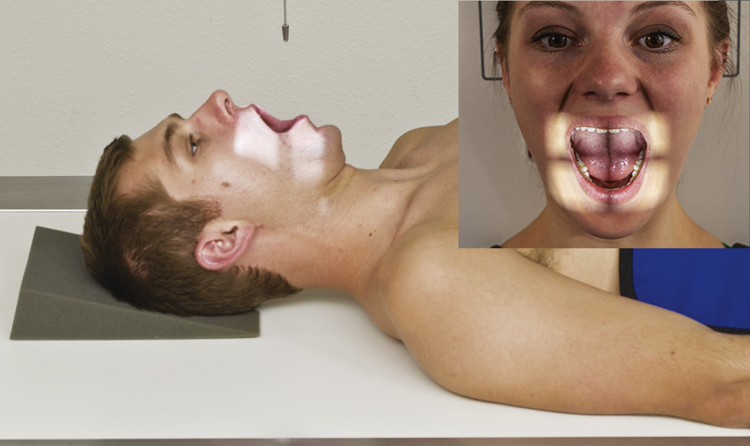
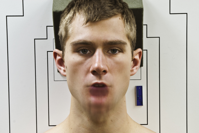
Patient Position—Supine or Erect Position
Position patient in supine or erect position with arms by sides. Place head on table surface, providing immobilization if needed.
Part Position

- • Align midsagittal plane to central ray (CR) and midline of table and/or IR.
- • Adjust head so that, with mouth open, a line from lower margin of upper incisors to the base of the skull (mastoid tips) is perpendicular to table and/or IR, or angle the CR accordingly.
- • Ensure that no rotation of the head (mandibular angles and mastoid tips equal distances from IR) or thorax exists.
- • Ensure that mouth is wide open during exposure. Do this as the last step and work quickly, because it is difficult to maintain this position (Fig. 8.46).
CR
Recommended Collimation
Collimate tightly on four sides to anatomy of interest.
Respiration
Suspend respiration.
NOTE: Make sure that when patient is instructed to open the mouth, only the lower jaw moves. Instruct the patient to keep the tongue in the lower jaw to prevent its shadow from superimposing the atlas and axis.
If the upper odontoid process cannot be demonstrated with correct positioning, perform Fuchs or Judd method (p. 321).
AP Axial Projection: Cervical Spine
Clinical Indications
Technical Factors

Shielding
Shield radiosensitive tissues outside region of interest.
Patient Position—Supine or Erect Position
Position patient in the supine or erect position, with arms by sides.
Part Position
- • Align midsagittal plane to CR and midline of table and/or IR.
- • Adjust head so that a line from lower margin of upper incisors to the base of the skull (mastoid processes) is perpendicular to table and/or IR. Line from tip of mandible to base of skull should be parallel to angled CR (Fig. 8.49).
- • Ensure no rotation of the head or thorax exists.
CR
Recommended Collimation
Collimate on four sides to anatomy of interest.
Respiration
Suspend respiration. Patient should not swallow during exposure.
NOTE: Cephalad angulation directs the beam between the overlapping cervical vertebral bodies to demonstrate the intervertebral disk spaces better. Angle the CR 15° when the patient is supine, or if there is less lordotic curvature. Angle the CR 20° when the patient is erect, or when more lordotic curvature is evident. The kyphotic (exaggerated curvature of the thoracic spine) patient will require an angle of more than 20°.


Anterior and Posterior Oblique Positions: Cervical Spine
WARNING: For trauma patients, do not remove cervical collar and do not move head or neck until authorized by a physician who has evaluated the horizontal beam lateral image or CT scan of the cervical spine.
Clinical Indications
- • Pathology involving the cervical spine and adjacent soft tissue structures, including stenosis involving the intervertebral foramen
- • Both right and left oblique projections should be taken for comparison purposes. Anterior oblique positions—RAO, LAO—are preferred because of reduced thyroid doses.
Technical Factors

Shielding
Shield radiosensitive tissues outside region of interest.
Patient Position—Erect or Recumbent Position
The erect position preferred (sitting or standing), but recumbent is possible if the patient’s condition requires.
Part Position
- • Align midsagittal plane to CR and midline of table and/or IR.
- • Place patient’s arms at side; if patient is recumbent, place arms as needed to help maintain position.
- • Rotate body and head into 45° oblique position. Use protractor or other angle gauge as needed to ensure 45° angle (see NOTE) (Figs. 8.52 and 8.53).
- • Protract chin to prevent mandible from superimposing vertebrae. Elevate chin to place acanthiomeatal line (AML) parallel with floor (insert). Excessive skull and neck extension will superimpose base of skull over posterior arch of C1.
CR
Anterior Oblique (RAO, LAO)
Posterior Oblique (RPO, LPO)
Recommended Collimation
Collimate on four sides to anatomy of interest.
Respiration
NOTE: Departmental option: The head may be turned toward IR to a near-lateral position. This results in some rotation of upper vertebrae but may help to prevent superimposition of mandible on upper vertebrae.


Lateral Position (Erect): Cervical Spine
Trauma patients: See lateral horizontal beam, p. 318.
Clinical Indications
Technical Factors

Shielding
Shield radiosensitive tissues outside region of interest.
Patient Position—Lateral Position
Position patient in the erect lateral position, either sitting or standing, with shoulder against vertical IR.
Part Position
- • Align midcoronal plane to CR and midline of table and/or IR.
- • Center IR to CR, which should place top of IR about 1 to 2 inches (2.5 to 5 cm) above the external auditory meatus (EAM) (Fig. 8.56).
- • Depress shoulders (for equal weights to both arms [see NOTE 2]). Ask patient to relax and drop shoulders down and forward as far as possible. (Do this as the last step before exposure because this position is difficult to maintain.)
- • Elevate chin to place AML parallel with floor. Protract chin (to prevent superimposition of the mandible on upper vertebrae).
CR
Recommended Collimation
Collimate on four sides to anatomy of interest.
Respiration
Suspend respiration on full expiration (for maximum shoulder depression).
NOTE 1: Long (72 inches [180 cm]) SID compensates for increased OID and provides for greater spatial resolution.
NOTE 2: Adding weights (5–10 lb [2.3–4.5 kg]) with straps suspended from each wrist may help in pulling down shoulders.


Lateral, Horizontal Beam—Trauma: Cervical Spine
WARNING: For trauma patients, do not remove cervical collar and do not move head or neck until authorized by a physician who has evaluated the horizontal beam lateral image or CT of the cervical spine. Many emergency departments routinely order CT to rule out fracture, subluxation, or other indications of cervical instability prior to performance of any radiographic procedures.
Clinical Indications
Technical Factors

Shielding
Shield radiosensitive tissues outside region of interest.
Patient Position
Place patient in the supine position on stretcher or radiographic table.
Part Position
- • Do not manipulate or move head or neck or remove cervical collar if present.
- • Support IR vertically against shoulder, or place stretcher next to vertical grid device.
- • Center IR to CR, which should place top of image receptor about 1 to 2 inches (2.5 to 5 cm) above EAM (Fig. 8.59).
- • Depress shoulders (see NOTE 3).
CR
Recommended Collimation
Collimate on four sides to anatomy of interest.
Respiration
Suspend respiration on full expiration (for maximum shoulder depression).
NOTE 1: Longer SID results in less magnification with increased image sharpness.
NOTE 2: Generally, a nongrid image receptor can be used for smaller or average-sized patients because of increased OID and the resultant air gap effect.
NOTE 3: Traction on arms will help depress shoulders but should be done only by a qualified assistant and/or with the consent or assistance of a physician. Protective apron must be worn and close collimation must be done to reduce any excessive exposure to assistant or physician.


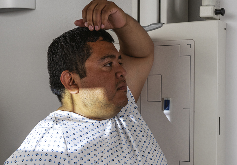
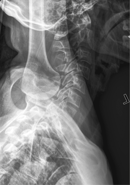
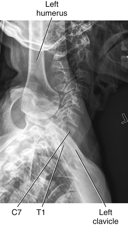
Cervicothoracic (C5-T3) Lateral Position: Cervical Spine
Swimmer’s
Clinical Indications
- • Pathology involving the inferior cervical spine, superior thoracic spine, and adjacent soft tissue structures
- • Various fractures (including compression fractures) and subluxation
- • This is a good projection when C7 to T1 is not visualized on the lateral cervical spine, or when the upper thoracic vertebrae are of special interest on a lateral thoracic spine.
Technical Factors
- • SID—60–72 inches (150–180 cm)
- • IR size—10 × 12 inches (24 × 30 cm), portrait
- • Grid
- • Specially designed compensating filter useful for obtaining uniform brightness (see Chapter 1 for more information on compensating filters)
- • kVp range: 75–95

Shielding
Shield radiosensitive tissues outside region of interest.
Patient Position—Erect or Recumbent Position
Place patient in preferred erect position (sitting or standing). The radiograph may be performed in the recumbent position if the patient’s condition requires.
Part Position
- • Align midcoronal plane to CR and midline of table and/or IR.
- • Place patient’s arm and shoulder closest to the IR up, flexing elbow and resting forearm on head for support.
- • Position arm and shoulder furthest from the IR down and rotate slightly posterior, to place the remote humeral head posterior to vertebrae (Fig. 8.62).
- • Ensure that no rotation of thorax and head exists.
CR
Recommended Collimation
Collimate on four sides to anatomy of interest.
Respiration
Suspend respiration on full expiration.
NOTE: A slight caudad angulation of 3° to 5° may be necessary to help separate the two shoulders farthest from the IR.
Optional Breathing Technique
If patient can cooperate and remain immobilized, a low mA and 3- or 4-second exposure time can be used, with patient breathing short, even breaths during the exposure to blur out overlying lung structures.
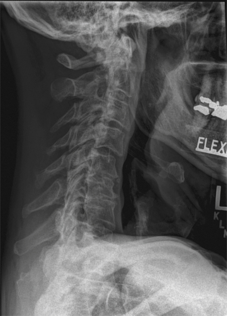
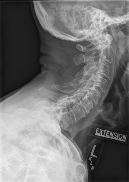
Lateral Positions—Hyperflexion and Hyperextension: Cervical Spine
WARNING: Never attempt these positions on a trauma patient until authorized by a physician who has evaluated the horizontal beam lateral image or CT scan of the cervical spine.
Clinical Indications
Technical Factors

Shielding
Shield radiosensitive tissues outside region of interest.
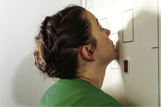
Patient Position—Erect Lateral Position
Place patient in erect lateral position, either sitting or standing, with arms at sides.
Part Position
- • Align midcoronal plane to CR and midline of table and/or IR.
- • Ensure a true lateral position, with no rotation of pelvis, shoulders, or head.
- • Relax and depress shoulders as far as possible (weights on each arm may be used).
- • For hyperflexion: Depress chin until it touches the chest or as much as patient can tolerate (do not allow patient to move forward to ensure that entire cervical is included on IR) (Fig. 8.65).
- • For hyperextension: Raise chin and tilt head back as much as possible (do not allow patient to move backward to ensure that entire cervical spine is included on IR) (Fig. 8.66).
CR
Recommended Collimation
Collimate on four sides to anatomy of interest.
Respiration
Suspend respiration on full expiration.
NOTE: These are uncomfortable for patient; do not keep patient in these positions longer than necessary.

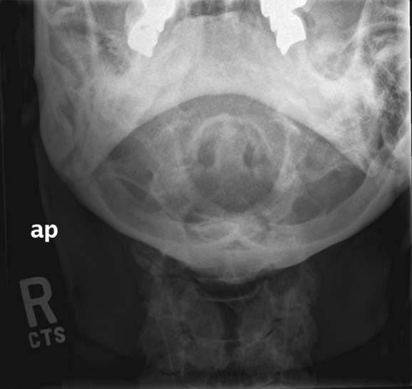
AP or PA Projection for C1–C2 (Odontoid Process–Dens): Cervical Spine
Fuchs Method (Ap) Or Judd Method (Pa)
WARNING: For trauma patients, do not remove cervical collar and do not move head or neck until authorized by a physician who has evaluated the horizontal beam lateral image or CT scan of the cervical spine. The cervical spine must be cleared for fracture or subluxation prior to performing these projections.
One of these projections is useful for demonstrating the superior portion of the dens when this area is not well visualized on the AP open mouth cervical spine projection.
Clinical Indications
Technical Factors

Shielding
Shield radiosensitive tissues outside region of interest.
Patient and Part Position
Position patient supine (AP) or prone (PA) with midsagittal plane aligned to CR and midline of table and/or IR.
AP (Fuchs Method)
- • Elevate chin as needed to bring mentomeatal line (MML) near perpendicular to tabletop (adjust CR angle as needed to be parallel to MML) (Fig. 8.69).
- • Ensure that no rotation of head exists (angles of mandible equidistant to tabletop).
- • CR is parallel to MML, directed to inferior tip of mandible.
- • Center IR to CR.
PA (Judd Method)
- • This is a reverse position to the supine position. Chin is resting on tabletop and is extended to bring MML near perpendicular to table (may adjust CR as needed to be parallel to MML) (Fig. 8.70).
- • Ensure that no rotation of head exists.
- • Ensure that CR is parallel to MML, through midoccipital bone, about 1 inch (2.5 cm) inferior to mastoid tips and angles of mandible.
- • Center IR to CR.
Recommended Collimation
Collimate tightly on four sides to anatomy of interest.
Respiration
Suspend respiration.

AP “Wagging Jaw” Projection: Cervical Spine
Ottonello Method
WARNING: For trauma patients, do not remove cervical collar and do not move head or neck until authorized by a physician who has evaluated the horizontal beam lateral image or CT scan of the cervical spine.
Clinical Indications
Technical Factors
Shielding
Shield radiosensitive tissues outside region of interest.
Patient Position—Supine Position
Position patient in the supine position with arms at side and head on table surface, providing immobilization if needed.
Part Position
- • Align midsagittal plane to CR and midline of table and/or IR.
- • Adjust head so that a line drawn from lower margin of upper incisors to the base of the skull (mastoid tips) is perpendicular to table and/or IR (Figs. 8.73 and 8.74).
- • Ensure no rotation of the head or thorax exists.
- • Mandible must be in continuous motion during exposure.
- • Ensure that only the mandible moves. The head must not move, and the teeth must not make contact.
CR
Recommended Collimation
Collimate on four sides to anatomy of interest.
Respiration
Suspend respiration.
NOTE: Practice with patient before exposure to ensure that only the mandible is moving continuously, and that teeth do not make contact.


AP Axial Projection—Vertebral Arch (Pillars): Cervical Spine
WARNING: For trauma patients, do not remove cervical collar and do not move head or neck until authorized by a physician who has evaluated the horizontal beam lateral image or CT scan of the cervical spine.
Clinical Indications
Pathology or trauma involving the posterior vertebral arch (particularly the pillars) of C4 to C7 and spinous processes of cervicothoracic vertebrae with whiplash-type injuries (see previous warning)
Technical Factors
Shielding
Shield radiosensitive tissues outside region of interest.
Patient Position—Supine Position
Position patient in the supine position with arms at side.
Part Position
- • Align midsagittal plane to CR and midline of table and/or IR.
- • Hyperextend the neck if patient is able (see warning above) (Fig. 8.77).
- • Ensure that no rotation of the head or thorax exists.
CR
Recommended Collimation
Collimate on four sides to anatomy of interest.
Respiration
Suspend respiration. Ask patient to not swallow during the exposure.
NOTE: Sufficient hyperextension of neck and caudal CR angle is essential for demonstrating the posterior aspects of the mid and lower cervical vertebrae. The amount of the CR angle (20° to 30°) is determined by the amount of natural cervical lordotic curvature. Some support may have to be placed under the shoulders for sufficient hyperextension.


AP Projection: Thoracic Spine
Clinical Indications
Technical Factors

Shielding
Shield all radiosensitive tissues outside region of interest.
Patient Position—Recumbent and Erect Position
- • Position patient supine (preferred) with arms at side and head on table or on a thin pillow. If patient cannot tolerate the supine position, place erect with arms at side and weight evenly distributed on both feet.
- • The anode heel effect will create more uniform density throughout the thoracic spine. Place patient so the more intense aspect of the beam (cathode side) is over the thoracolumbar region of the spine.
Part Position
- • Align midsagittal plane to CR and midline of table and/or IR (Fig. 8.80).
- • Flex knees and hips to reduce thoracic curvature.
- • Ensure that no rotation of thorax or pelvis exists.
CR
Recommended Collimation
Collimate on two sides of anatomy (four sides if possible).
Respiration
Suspend respiration on expiration. Expiration reduces air volume in thorax for more uniform brightness and density.


Lateral Position: Thoracic Spine
Clinical Indications
NOTE: When upper thoracic vertebrae are of interest, perform the cervicothoracic (swimmer’s) lateral position in addition to routine thoracic spine projections (see p. 319).
Technical Factors

Shielding
Shield all radiosensitive tissues outside region of interest.
Patient Position—Lateral Recumbent or Erect Position
Position patient in the lateral recumbent position, with head on pillow and knees flexed. For the erect position, place arms outstretched, with weight evenly distributed on both feet.
Part Position
- • Align posterior half of thorax (between midcoronal plane and posterior aspect of thorax) to CR and midline of table and/or IR (Fig. 8.83).
- • Raise patient’s arms to right angles to body with elbows flexed.
- • Support waist so entire spine is near parallel to table. Palpate spinous processes to determine alignment (see NOTE 2).
- • Flex hips and knees, with support between the knees.
- • Ensure that no rotation of shoulders or pelvis exists.
CR
Recommended Collimation
Collimate on two sides of anatomy (four sides if possible).
Respiration
Use orthostatic breathing technique or suspend respiration. Suspended full inspiration can provide maximum uniform density of the vertebrae visualized above the diaphragm. A breathing technique is useful to blur unwanted rib and lung markings overlying thoracic vertebrae if the patient can cooperate. This breathing technique requires a minimum of 2 or 3 seconds of exposure time with a low mA setting.
NOTE 1: Significant amounts of secondary and scatter radiation are generated. Close collimation and placement of a lead mat posterior to the part are essential to maintaining image quality. This is particularly important with digital imaging.
NOTE 2: The optimal amount of support under the waist will cause the lower vertebrae to be the same distance from the tabletop as the upper vertebrae. A patient with wide hips will require substantially more support under the waist to prevent sag. A patient with broad shoulders may require a 10° to 15° cephalic CR angle if waist is not supported.


Anterior or Posterior Oblique Position: Thoracic Spine
Clinical Indications
Technical Factors

Shielding
Shield all radiosensitive tissues outside region of interest.
Patient Position—Oblique Anterior or Posterior Recumbent or Erect Positions
Initially position patient in the lateral recumbent position (preferred), with head on pillow and knees flexed. For the erect position, ensure equal distribution of weight on both feet.
Part Position
Posterior Oblique Position (Recumbent)
- • LPO or RPO: Place arm nearest table up and forward; arm nearest tube down and posterior (Fig. 8.86).
Anterior Oblique Position (Recumbent)
- • LAO or RAO: Place arm nearest table down and posterior; arm nearest tube up and forward (Fig. 8.87).
Erect Anterior Oblique Position
- • Distribute patient’s weight equally on both feet.
- • Rotate total body, shoulders, and pelvis 20° anterior from lateral.
- • Flex elbow and place arm nearest IR on hip.
- • Raise opposite arm and rest on top of head (Fig. 8.88).
CR
Recommended Collimation
Collimate on two sides of anatomy (four sides if possible).
Respiration
Suspend respiration on full expiration.
NOTE: Patient’s thorax is 20° from lateral; some type of angle guide may be used to determine correct rotation (see Figs. 8.86 and 8.87).
Radiographs may be taken as posterior or anterior obliques. Anterior obliques are recommended because of significantly lower breast dose.


Radiographs for Critique
This section consists of an ideal projection (Image A) along with one or more projections that may demonstrate positioning and/or technical errors. Critique Figures C8.91 through C8.96. Compare Image A to the other projections and identify the errors. While examining each image, consider the following questions:
-
- 1. Is all essential anatomy demonstrated on the image?
- 2. What positioning errors are present that compromise image quality?
- 3. Are technical factors optimal?
- 4. Is there evidence of collimation and pre-exposure anatomic side markers visible on the image?
- 5. Do these errors require a repeat exposure?


