Chapter 9: Lumbar Spine, Sacrum, and Coccyx
Contributions By Patti Ward, PhD, RT(R), Contributors To Past Editions Alex Backus, MS, RT(R), and Cindy Murphy, BHSc, RT(R), ACR
Radiographic Anatomy
This chapter describes anatomy and positioning of the lumbar, sacrum, and coccyx sections of the vertebral column. Refer to Chapter 8 for more detailed information about vertebral anatomy.
Lumbar Vertebrae
The largest individual vertebrae are the five lumbar vertebrae. These vertebrae are the strongest in the vertebral column because the load of body weight increases toward the inferior end of the column. For this reason, the cartilaginous disks between the inferior lumbar vertebrae are common sites for injury and pathologic processes.
Lateral and Superior Perspectives
Patients typically have five lumbar vertebrae located just inferior to the 12 thoracic vertebrae. Fig. 9.1 illustrates the lateral perspective of a typical lumbar vertebra. Lumbar vertebral bodies are larger in comparison with thoracic and cervical vertebral bodies. The most inferior body, L5, is the largest. The transverse processes are small, whereas the posteriorly projecting spinous process is bulky and blunt. The palpable lower tip of each lumbar spinous process lies at the level of the intervertebral disk space inferior to each vertebral body.
Intervertebral Foramina
Fig. 9.2 shows the intervertebral foramen situated 90° relative to the midsagittal plane. Intervertebral foramina are spaces or openings between pedicles when two vertebrae are stacked on each other. Along the upper surface of each pedicle is a half-moon-shaped area called the
superior vertebral notch,
and along the lower surface of each pedicle is another half-moon-shaped area called the
inferior vertebral notch.
When vertebrae are stacked, the superior and inferior vertebral notches line up, and the two half-moon-shaped areas form a single opening, the intervertebral foramina (see Chapter 8, Figs. 8.8 and 8.9). Therefore, between every two vertebrae are two intervertebral foramina, one on each side, through which important spinal nerves and blood vessels pass. The intervertebral foramina in the lumbar region are demonstrated best on a lateral radiographic image.
Zygapophyseal Joints
Each typical vertebra has four articular processes that project from the area of the junction of the pedicles and laminae. The processes that project upward are called the
superior articular processes
and the processes that project downward are the
inferior articular processes.
The term
facet
(fas-ət) sometimes is used interchangeably with the term
zygapophyseal joint;
the facet is actually only the articulating surface instead of the entire superior or inferior articular process. Fig. 9.1 shows the relative positions of the superior and inferior lumbar articular processes from the lateral perspective.
The zygapophyseal joints form an angle open from 30° to 50° to the midsagittal plane, as shown in Fig. 9.2. The upper or proximal lumbar vertebrae are nearer the 50° angle and the lower or distal lumbar vertebrae are nearer 30°. Radiographic demonstration of the zygapophyseal joints is achieved by rotating the patient’s body an average of 45°.
The laminae form a bridge between the transverse processes, lateral masses, and spinous process (see Fig. 9.2). The portion of each lamina between the superior and inferior articular processes is the
pars interarticularis.
The pars interarticularis is demonstrated radiographically on the oblique lumbar image.
Posterior and Anterior Perspectives
Fig. 9.3 demonstrates the general appearance of a lumbar vertebra as seen from the anterior and posterior perspectives. Anteroposterior (AP) or posteroanterior (PA) radiographic projections of the lumbar spine demonstrate the spinous processes superimposed on the vertebral bodies. The transverse processes are demonstrated protruding laterally beyond the edges of the vertebral body.


Sacrum
The sacrum is inferior to the lumbar vertebrae.
Anterior Perspective
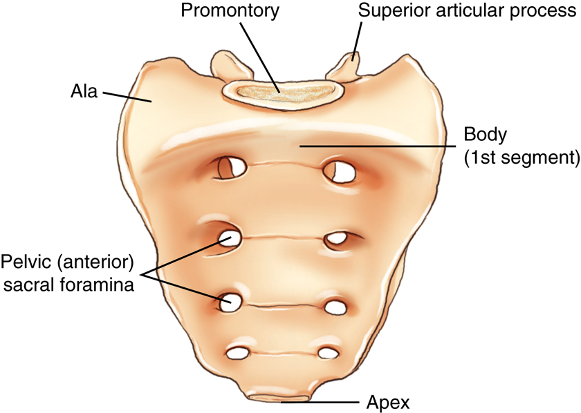
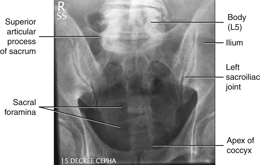
Fig. 9.4 illustrates the concave anterior surface of a sacrum. The bodies of the original five segments fuse into a single bone in the adult. The sacrum is shovel-shaped, with the apex pointed inferiorly and anteriorly. Four sets of pelvic (anterior) sacral foramina (similar to intervertebral foramina in more superior sections of the spine) transmit nerves and blood vessels.
The alae, or wings, of the sacrum are large masses of bone lateral to the first sacral segment. The two superior articular processes of the sacrum form zygapophyseal joints with the inferior articular processes of the fifth lumbar vertebrae.
Lateral Perspective
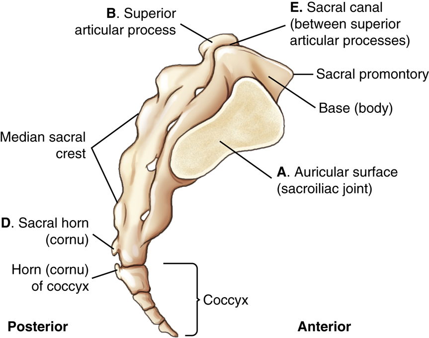
Fig. 9.5 clearly illustrates the dominant convex curve (posterior perspective) of the sacrum and forward projection of the coccyx. These curves determine how the central ray must be angled differently for AP radiographic projections of the sacrum or coccyx.
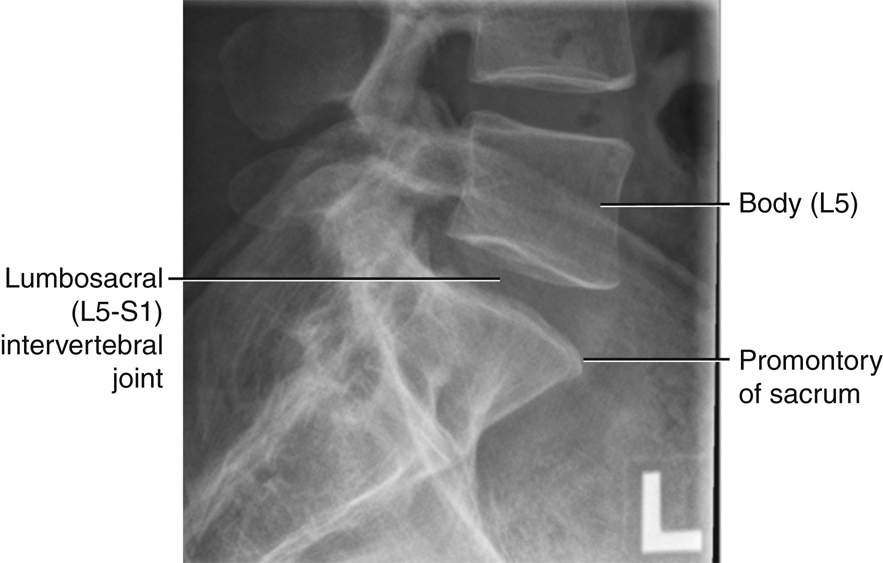
The anterior ridge of the body of the first sacral segment helps form the posterior wall of the inlet of the true pelvis and is termed the
promontory
of the sacrum; it is best demonstrated from a lateral perspective (see Fig. 9.5).
Posterior to the body of the first sacral segment is the opening to the sacral canal, which is a continuation of the vertebral canal and contains certain sacral nerves. The median sacral crest is formed by fused spinous processes of the sacral vertebrae.
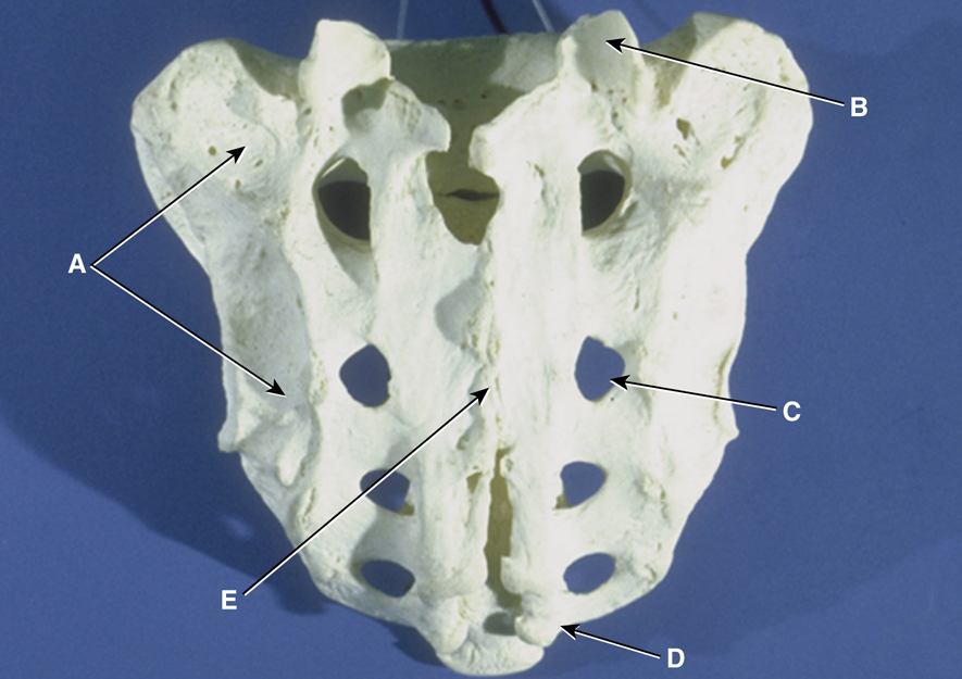
Figs. 9.5 and 9.6 illustrate the relative roughness and irregularity of the posterior surface of the sacrum compared with the anterior or pelvic surface.
The sacrum articulates with the ilium of the pelvis at the auricular surface (marked A in Figs. 9.5 and 9.6) to form the sacroiliac joint. The auricular surface is so named because of its resemblance in shape to the auricle of the ear. Refer to Chapter 7 for more detailed information about the sacroiliac joints.
Posterior Sacrum
Fig. 9.6 is a photograph of an actual sacrum, as seen from the posterior aspect. Clearly seen is the large, wedge-shaped auricular surface (A), which articulates with a similar surface on the ilium to form the sacroiliac joint. Each sacroiliac joint opens obliquely at an angle of 30°.
The articulating facets of the superior articular processes (B) also open to the rear and are shown on this photograph. There are eight posterior sacral foramina (C), four on each side, corresponding to the same number of anterior sacral foramina.
The sacral horns (cornua; D) are seen as small bony projections at the very inferoposterior aspect of the sacrum. Remnants of the enclosed sacral canal (E) also can be seen. (Deteriorating bone leaves the canal partially open on this bone specimen.)
Coccyx
Anterior Coccyx
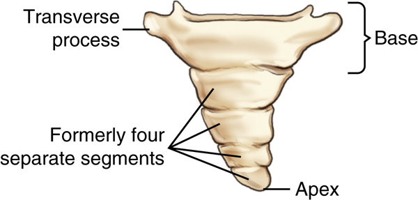
The most distal portion of the vertebral column is the coccyx. The anterior surface of the tailbone, or coccyx, is illustrated in Fig. 9.7. This portion of the vertebral column has greatly regressed in humans, so little resemblance to vertebrae remains. Three to five coccygeal segments (an average of four) have fused in the adult to form the single coccyx. The drawing in Fig. 9.7 demonstrates four formerly separate segments present in a child, now fused into a single bone as an adult. The photograph of a coccyx in Fig. 9.8 demonstrates five segments now mostly fused in the adult coccyx.
The most superior segment is the largest and broadest of the four sections and even has two lateral projections that are small
transverse processes.
The distal pointed tip of the coccyx is termed the
apex,
whereas the broader superior portion is termed the
base.
Occasionally, the second segment does not fuse solidly with the larger first segment (see Fig. 9.8); however, the coccyx usually is one small, insignificant end of the vertebral column.
Posterior Coccyx
The posterior aspect of an actual coccyx is pictured in Fig. 9.8 along with a common U.S. postage stamp to allow comparison of the two sizes. (Note that a portion of the transverse process is missing on the upper right aspect of this specimen.)
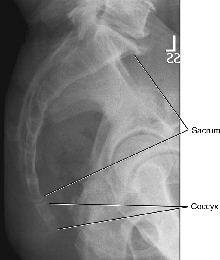
Lateral Sacrum and Coccyx Radiograph
The lateral sacrum on the radiograph in Fig. 9.9 is seen as a large solid bone as compared with the much smaller coccyx. The long axis of the sacrum is shown to be angled posteriorly, requiring a cephalad angle of the central ray (CR) on an AP projection. This angle is greater in an average woman as compared with an average man.
Ordinarily, the coccyx curves anteriorly, as can be seen and identified on this lateral radiograph, so that the apex points toward the symphysis pubis of the anterior pelvis. This forward curvature frequently is more pronounced in men and is less pronounced, with less curvature, in women. The coccyx projects into the birth canal in the woman and, if angled excessively forward, can impede the birth process.
The most common injury associated with the coccyx results from a direct blow to the lower vertebral column when a person is in a sitting position. This type of injury results from falling backward with a forceful sitting action. Also of note is that because of the shape of the female pelvis and the more vertical orientation of the coccyx, a female patient is more likely to experience a fracture of the coccyx than a male patient.

Anatomy Review
Superoinferior Projection
The radiograph in Fig. 9.10 demonstrates certain parts of an individual lumbar vertebra taken from a disarticulated skeleton; these parts are labeled as follows:
Lateral Position
Parts labeled A through F on the lateral view (Fig. 9.11) of a disarticulated lumbar vertebra are as follows:
-
- A. Body
- B. Inferior vertebral notch, or the floor of the pedicle making up the upper portion of the rounded intervertebral foramen
- C. Area of the articulating facet of the inferior articular process (actual articular facet not shown on this lateral view); makes up the zygapophyseal joints when vertebrae are stacked
- D. Spinous process
- E. Superior articular process
- F. Pedicle
Note that this lateral view would open and demonstrate the intervertebral foramina well (the larger round opening directly under B, the inferior vertebral notch). However, it would not demonstrate the zygapophyseal joints; this would require a 45° oblique view.
AP Projection
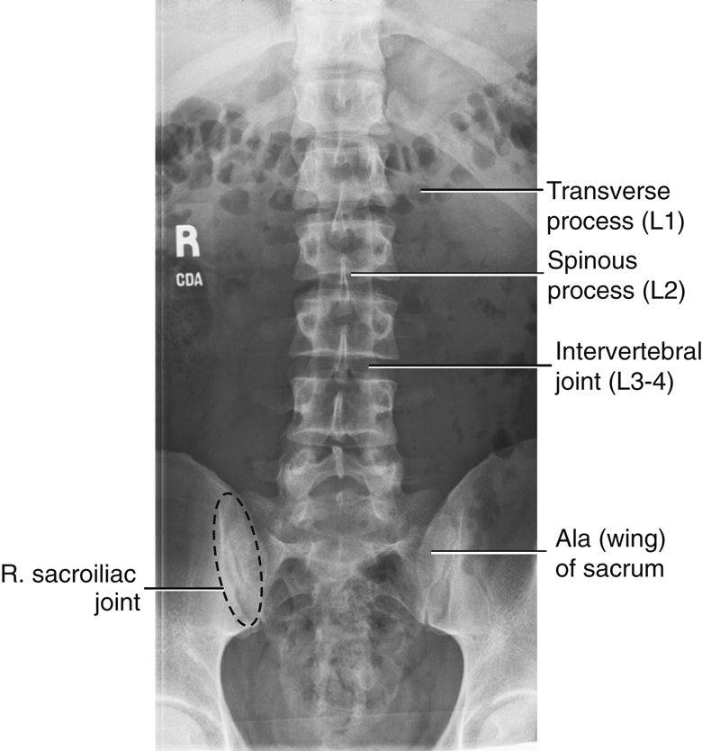
Individual structures are more difficult to identify when the vertebrae are superimposed by the soft tissues of the abdomen, as demonstrated on the AP lumbar spine radiograph in Fig. 9.12. These structures, labeled A through F, are as follows:
The facets of the inferior and superior articular processes (D and E) create the zygapophyseal joint not visualized on this AP projection. However, the joint is demonstrated on a 45° oblique projection of lumbar vertebrae (see Fig. 9.16).


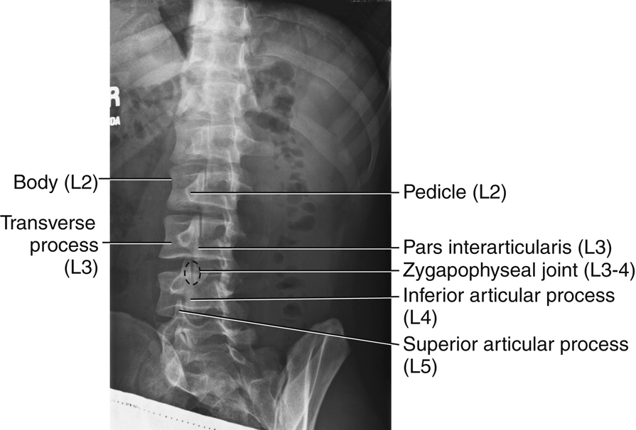
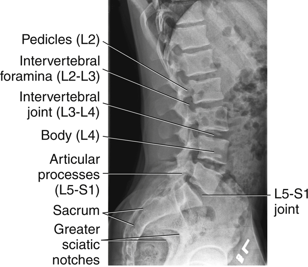
Lateral Lumbosacral Spine
A radiograph of the entire lumbosacral spine in the lateral position (Fig. 9.13) shows the following:
AP Lumbosacral Spine
The AP projection of the entire lumbosacral spine, shown in Fig. 9.14, is labeled as follows:
Oblique Lumbar Vertebrae
Appearance of “Scottie Dog”
Any bone and its parts, when seen in an oblique position, are more difficult to recognize than the same bone seen in the conventional frontal or lateral view. A vertebra is no exception; however, imagination can help us in the case of the lumbar vertebrae. A good 45° oblique projects the various structures in such a way that a “Scottie dog” seems to appear. Fig. 9.15 shows the various components of the Scottie dog. The head and neck of the dog are probably the easiest features to recognize. The neck is one pars interarticularis (part of the lamina that primarily makes up the shoulder region of the dog). The ear of the dog is one superior articular process, whereas the eye is formed by one pedicle. One transverse process forms the nose. The front legs are formed by one inferior articular process.
Oblique Lumbar Radiograph
Fig. 9.16 shows the Scottie dog appearance that should be visible on oblique radiographs of the lumbar spine. The right posterior oblique (RPO) radiograph is labeled as follows:
-
- A. Nose of the Scottie dog, formed by one transverse process
- B. Eye, one pedicle seen on end
- C. Neck of the dog, which is the pars interarticularis
- D. Front leg of the dog, formed by one inferior articular process
- E. Pointed ear, one of the superior articular processes
- F. Zygapophyseal joint, formed by front leg of the Scottie above and ear of the Scottie below
Each of the five lumbar vertebrae should assume a similar Scottie dog appearance, with zygapophyseal joint spaces open on a correctly rotated lumbar radiograph.
Classification of Joints
Two types of classifications of joints, or articulations, involve the vertebral column.
Zygapophyseal Joints
The zygapophyseal joints between the superior and inferior articular processes are classified as synovial joints. These joints are lined with synovial membrane. They are diarthrodial, or freely movable, with a plane (gliding) type of movement.
Intervertebral Joints
The intervertebral joints between the bodies of any two vertebrae contain intervertebral disks that are made up of fibrocartilage and are only slightly movable. These joints, which are tightly bound by cartilage, thus are classified as cartilaginous joints. They are amphiarthrodial (slightly movable) joints of the symphysis subclass, similar to the intervertebral joints of the cervical and thoracic spine, as described in the preceding chapter.


A great deal of motion is not evident between any two vertebrae, but the combined effects of all vertebrae in the column allow a considerable range of motion. Possible movements include flexion, extension, lateral flexion (bending), and rotation. Certain radiographic examinations of the spinal column involving hyperflexion and hyperextension and/or right- and left-bending routines can measure this range of motion.
Intervertebral Foramina Versus Zygapophyseal Joints
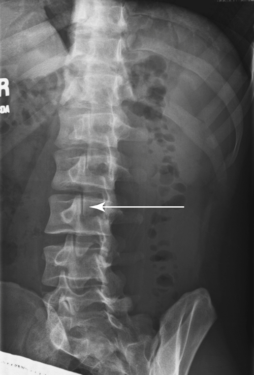
Intervertebral Foramina—Lateral Lumbar Spine
The intervertebral foramina for the lumbar spine are visualized on a true lateral projection, as demonstrated in Fig. 9.13.
Zygapophyseal Joints—Oblique Lumbar Spine
Positioning for oblique projections of the lumbar spine requires a good understanding of the anatomy of the vertebrae and the zygapophyseal joints. It is important to know how much to rotate the patient and which joint is being demonstrated.
Posterior Oblique
As the drawing and photographs of the skeleton demonstrate, the downside joints are visualized on posterior oblique positions. The downside zygapophyseal joints are not visible on the skeleton because they are “under” the bodies of the vertebrae (Fig. 9.17), but as seen on the inferosuperior sectional drawing, the downside joints would be demonstrated on a posterior oblique (Fig. 9.18). The RPO radiograph in Fig. 9.19, clearly shows the ears and legs of the Scottie dogs, or the right zygapophyseal joints (arrow).
Anterior Oblique
The anterior oblique position may be more comfortable for the patient and may allow the natural lumbar curvature of the spine to coincide with the divergence of the x-ray beam.
As demonstrated, an anterior oblique visualizes the upside joints. Therefore, a right anterior oblique (RAO) visualizes the upside, or left, zygapophyseal joints (Figs. 9.20, 9.21, and 9.22).
The degree of rotation depends on which area of the lumbar spine is of specific interest. A 45° oblique is used for the general lumbar region, but if interest is specifically focused on L1 or L2, the degree of rotation may be increased to 50°. If interest is in the L5–S1 area, rotation may be decreased to 30° from an AP or PA projection. Some variance is seen among patients but in general, the upper lumbar region requires more degrees of rotation than the lower regions. The reason is that the upper lumbar vertebrae take on some shape characteristics of the thoracic vertebrae, which require 70° of rotation to demonstrate the zygapophyseal joints, as described in Chapter 8.
Table 9.1 lists lumbar (L) spine joint and foramina positioning, and Table 9.2 lists joint classifications of the L spine.


Radiographic Positioning
Topographic Landmarks
Correct positioning for the coccyx, sacrum, and lumbar spine requires a thorough understanding of specific topographic landmarks that can be easily palpated.
The most reliable landmarks for the spine are various palpable bony prominences that are consistent from one person to another. However, the landmarks presented refer to an average-sized, healthy, erect, typically developed male or female. These landmarks vary in subjects with anatomic and, especially, skeletal anomalies. The very young and the very old also have slightly different features from those of the average adult. Refer to the bariatric patient considerations in the following pages for tips to locate bony anatomy when palpation is inadequate.
Lower Spine Landmarks
The drawings on the right illustrate various landmarks relative to the lower vertebral column (Fig. 9.23).
-
- A. This corresponds to the superior margin of the symphysis pubis. The prominence of the greater trochanter is at about the same level as the superior border of the symphysis pubis.
- B. The anterior superior iliac spine (ASIS) is approximately the same level (B) as the first or second sacral segment.
- C. This is the most superior portion of the iliac crest and is at approximately the same level as the junction of the L4–L5 vertebrae.
- D. The lowest margin of the ribs or lower costal margin (D) is at the approximate level of L2 to L3.
- E. The xiphoid tip is approximately at the level of T9–T10.

Positioning Considerations
Patient Radiation Protection
Use of gonadal shielding and close collimation is especially important in dose reduction because of the proximity of the lumbar spine, sacrum, and coccyx to the gonads. Gonadal shielding can and should always be used on male patients of reproductive age on coccyx, sacrum, or lumbar spine radiographs. The gonadal shield should be placed with the top edge of the shield at the lower margin of the symphysis pubis (Fig. 9.24).
If the area of interest includes the sacrum and/or coccyx, gonadal shielding for females may not be possible without obscuring essential anatomy.
Females of childbearing age always must be questioned regarding the possibility of pregnancy before any radiographic examination of the lower vertebral column is begun.
Patient Position
AP projections of the lumbar spine when the patient is recumbent are obtained with the knees flexed. Flexing the knees (Fig. 9.25) reduces the lumbar curvature (lordosis), bringing the back closer to the radiographic examination table and the lumbar vertebral column more parallel to the image receptor (IR). Also, flexing the knees allows for greater patient comfort.
The incorrect position is shown in Fig. 9.26, where the pelvis is tipped forward slightly when the lower limbs are extended, exaggerating the lumbar curvature.
PA Versus AP Projections
Even though the AP projection (with knees flexed) is a common part of the routine for the lumbar spine, the PA projection offers an advantage. The prone position places the lumbar spine with its natural lumbar curvature in such a way that the intervertebral disk spaces are almost parallel to the divergent x-ray beam. This position opens and provides better visualization of the margins of the intervertebral disk spaces. Another advantage of the PA projection in females is a lower ovarian dose, 25% to 30% less for a PA projection compared with an AP. However, a disadvantage of the PA projection is the increased object–image receptor distance (OID) of the lumbar vertebrae, which results in magnification unsharpness, especially for a patient with a large abdomen.
Exposure Factors
Higher kVp and lower mAs reduces patient doses for all imaging systems. Typically, digital kVp ranges are higher than analog systems. Although higher kVp will produce more scatter radiation, close collimation, use of grids, and table masking for lateral projections will minimize its impact on image quality.
Lead Masking on Tabletop
See the section Digital Imaging Considerations later in the chapter, which details the importance of this practice along with close collimation, especially with digital imaging.


Sid
The minimum SID is typically 40 inches (100 cm), but an increased SID of 42, 44, or even 48 inches (105, 110, or 120 cm) may be used in some departments to reduce magnification. This depends on equipment specifications and on department protocol.
Part-IR Alignment
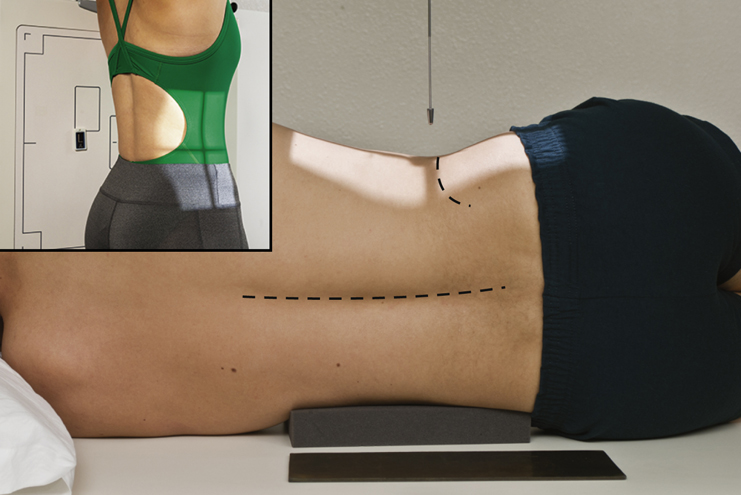
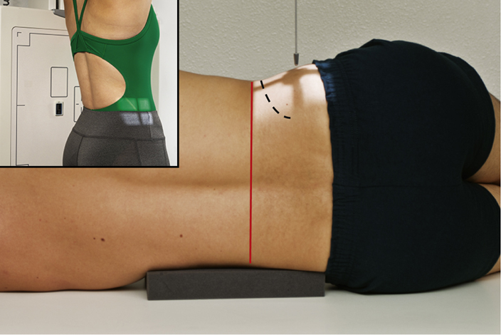
Correct part-IR alignment is important during radiography of the lower vertebral column to ensure that the beam passes through the intervertebral disk spaces. This alignment may require placement of a radiolucent sponge under the patient’s waist while in the lateral position to ensure that the spine is parallel with the IR (Fig. 9.27). If a sponge is required, the appropriate size is determined by the patient’s body habitus.
Special Patient Considerations
Pediatric Applications
Patient Motion and Safety
Two primary concerns in pediatric radiography are patient motion and safety. A clear explanation of this procedure is required if maximal trust and cooperation are to be obtained from the patient and guardian.
Careful immobilization is important for achieving proper positioning and reducing patient motion. A short exposure time helps reduce patient motion.
To secure their safety, pediatric patients should be continuously watched and cared for. See Chapter 16 for detailed communication strategies, immobilization techniques, and explanations.
Communication
Clear, simple instructions and communication are important, and distraction techniques such as toys or stuffed animals are effective in maintaining patient cooperation.
Immobilization
Pediatric patients (depending on age and condition) often are unable to maintain the required position. Use of immobilization devices to support the patient is recommended to reduce the need for the patient to be held, thus reducing radiation exposure. (Chapter 16 provides an in-depth description of these devices.) If the patient must be held by the guardian, the technologist must provide a lead apron and/or gloves and, if the guardian is female, it must be ensured that there is no possibility of pregnancy.
Technical Factors
Technical factors vary with patient size. Use of short exposure times (associated with the use of high mA) is recommended to reduce the risk of patient motion.
Geriatric Applications
Communication and Comfort
Sensory loss (e.g., eyesight, hearing) associated with aging may result in the need for additional assistance, time, and patience in achieving the required positions for spinal radiography in the geriatric patient. Decreased position awareness may cause these patients to fear falling off the radiography table when they are imaged in the recumbent position. Reassurance and additional care from the technologist help the patient to feel secure and comfortable.
If the examination is performed with the patient in the recumbent position, a radiolucent mattress or pad placed on the examination table provides comfort. Extra blankets may be required to keep the patient warm. Patients with severe kyphosis may be more comfortable if positioned for images in the erect position.

Technical Factors
Because of the high incidence of osteoporosis in geriatric patients, the kVp or mAs may require a decrease.
Older patients may have tremors or difficulty holding steady. Use of short exposure times (associated with the use of higher mA) is recommended to reduce the risk of motion.
Bariatric Patient Considerations
Palpation of topographic landmarks can be difficult with the bariatric patient. The top of the gonadal shield must not be above the symphysis pubis. To locate the symphysis pubis, ask the patient to flex the knees and hips. The symphysis pubis is slightly superior to the level of the crease of the thigh. It may be necessary to lift the abdominal panniculus adiposus (fatty apron) to visualize the crease.
1
Bariatric patients may present some challenges when positioning for lumbar spine, sacral, and coccygeal images. Additional density from adipose tissue and pannicular folds may require an increase in technical factors. An increase in kVp to improve penetration through additionally thick tissue may be necessary. mA and time may also be increased; however, a technologist must always follow recommendations based on the ALARA principle (exposure to the patient as low as reasonably achievable) to avoid excessive radiation exposure. Measures must also be taken to reduce scatter radiation exposure to the IR because of the increased amount of tissue. A grid can be used for anatomic structures over 10 cm to decrease the amount of scatter reaching the IR. Tight collimation to the anatomy of interest will also help to reduce the amount of scatter radiation reaching the IR. The location of the lumbar spine sacral and coccygeal anatomy will be aligned similarly in the general population of patients. Use known external landmarks and previously discussed tips for identifying the location of the anatomy of interest.
Digital Imaging Considerations
The following guidelines are important for digital imaging of the lumbar spine, sacrum, and coccyx:
- 1. Correct centering (this allows for accurate processing by the image reader): This is especially important for projections such as the L5–S1 joint, the sacrum, and/or the coccyx.
- 2. Close collimation and tabletop lead masking: This improves image quality by reducing scatter and secondary exposure to the highly sensitive digital image receptors.
- 3. Adherence to the ALARA principle in determining exposure factors: Increasing kVp for lumbar spine studies reduces patient dose.
- 4. Post-processing evaluation of exposure indicator: This becomes an important consideration with lumbar spine, sacrum, and coccyx projections to ensure optimum image quality with the least radiation to the patient. (Remember, some of these projections may include primary exposure, in addition to secondary and scatter radiation to the reproductive organs.)
Alternative Modalities and Procedures
Computed Tomography
Computed tomography (CT) is useful for evaluation of the vertebral column. A wide range of pathologic conditions is demonstrated on sectional images, including the presence and extent of fractures, disk disease, and neoplastic disease.
Magnetic Resonance Imaging
Magnetic resonance imaging (MRI) is superior for the evaluation of soft tissue structures of the lumbar spine (i.e., the spinal cord and intervertebral disk spaces).
Nuclear Medicine Technology
Nuclear medicine (NM) provides a sensitive diagnostic procedure, the radionuclide bone scan, for detection of skeletal pathologic processes. A radiopharmaceutical-tagged tracer element is injected that concentrates in areas of increased bone activity, demonstrating a hot spot on the nuclear medicine image. Any abnormal area is then investigated further with radiography.
Commonly, patients who are at risk or are symptomatic for skeletal metastases undergo a bone scan; patients with multiple myeloma are an exception to this. The vertebral column is a common site of skeletal metastases. Inflammatory conditions, Paget disease, neoplastic processes, and osteomyelitis also may be demonstrated on the bone scan.
Bone Densitometry
Bone densitometry is the noninvasive measurement of bone mass (see Chapter 20). The lumbar spine is often assessed in a bone density study. Causes for loss of bone mass (osteoporosis) include long-term steroid use, hyperparathyroidism, estrogen deficiency, advancing age, and lifestyle factors (e.g., smoking, sedentary lifestyle, alcoholism). Bone densitometry is accurate to within 1%, and the radiation skin dose is very low. Conventional radiography does not detect loss of bone until bone mass has been reduced by at least 30%.
Myelography
Myelography requires injection of contrast medium into the subarachnoid space via a lumbar or cervical puncture to visualize the soft tissue structures of the spinal canal. Lesions of the spinal canal, nerve roots, and intervertebral disks are demonstrated. Post-injection CT imaging may be included.
The increase in availability of CT and MRI has greatly reduced the number of myelograms performed. In addition to the superior diagnostic quality of these modalities, avoidance of invasive puncture and contrast injection is beneficial for the patient.
Clinical Indications
- Ankylosing spondylitis: This systemic illness of unknown origin involves the spine and larger joints. It predominantly affects men from ages 20 to 40 years and results in pain and stiffness that result from inflammation of the sacroiliac, intervertebral, and costovertebral joints, in addition to paraspinal calcification, with ossification and ankylosis (union of bones) of the spinal joints. It may cause complete rigidity of the spine and thorax, which usually is seen first in the sacroiliac joints.
- Fractures reflect lack of continuity of a structure:
-
- • Compression fractures may be due to trauma, osteoporosis, or metastatic disease. The superior and inferior surfaces of the vertebral body are driven together, producing a wedge-shaped vertebra. For patients with osteoporosis or other vertebral pathologic processes, the force needed to cause this fracture type may be minor (e.g., lifting light objects). This type of fracture rarely causes a neurologic deficit.
- • Chance fractures result from a hyperflexion force that causes fracture through the vertebral body and posterior elements (e.g., spinous process, pedicles, facets, transverse processes). Patients wearing lap-type seat belts are at risk because these belts act as a fulcrum during sudden deceleration.
- Herniated nucleus pulposus (HNP), also commonly known as a herniated lumbar disk (slipped disk), is usually due to trauma or improper lifting. The soft inner part of the intervertebral disk (nucleus pulposus) protrudes through the fibrous outer layer, pressing on the spinal cord or nerves. It occurs most frequently at the L4–L5 levels, causing sciatica (an irritation of the sciatic nerve that passes down the posterior leg). Plain radiographs do not demonstrate this condition but can be used to rule out other pathologic processes, such as neoplasia and spondylolisthesis. Myelography once was indicated to visualize this pathologic process. CT and MRI are now the modalities of choice.
- Lordosis describes the normal concave curvature of the lumbar spine and an abnormal or exaggerated concave lumbar curvature. This condition may result from pregnancy, obesity, poor posture, rickets, or tuberculosis of the spine. A lateral projection of the spine will best demonstrate the extent of lordosis.
- Metastases are primary malignant neoplasms that spread to distant sites via blood and lymphatics. The vertebrae are common sites of metastatic lesions, which may be characterized and visualized on the image as follows:
- Scoliosis is lateral curvature of the vertebral column that usually occurs with some rotation of the vertebra. It involves the thoracic and lumbar regions. Dextroscoliosis is the exaggerated curvature to the right. Levoscoliosis is the exaggerated curvature to the left.
- Spina bifida is a congenital condition in which the posterior aspects of the vertebrae fail to develop, thus exposing part of the spinal cord. This condition varies greatly in severity and occurs most often at L5 (see clinical indications in Chapter 16).
- Spondylolisthesis involves the forward movement of one vertebra in relation to another. It is commonly due to a developmental defect in the pars interarticularis or may result from spondylolysis or severe osteoarthritis. It is most common at L5–S1 but also occurs at L4–L5. Severe cases require a spinal fusion.
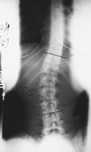
- Spondylolysis is the dissolution of a vertebra, such as from aplasia (lack of development) of the vertebral arch and separation of the pars interarticularis of the vertebra. On the oblique projection, the neck of the Scottie dog appears broken. It is most common at L4 or L5.
See Table 9.3 for a summary of clinical indications.
TABLE 9.3
| Condition or Disease | Most Common Radiographic Examination | Possible Radiographic Appearance | Exposure Factor Adjustment a |
|---|---|---|---|
| Ankylosing spondylitis | AP, lateral lumbar spine, sacroiliac joints; nuclear medicine bone scan | Vertebral column becoming fused, appearance of piece of bamboo; anterior longitudinal ligaments calcifying | None |
| Fractures | |||
| Compression | AP, lateral lumbar spine, CT | Anterior wedging of vertebrae; loss of body height | None or slight decrease (−), depending on severity |
| Chance | AP, lateral lumbar spine, CT | Fracture through vertebral body and posterior elements | None |
| Herniated nucleus pulposus (HNP) (herniated lumbar disk) | AP, lateral lumbar spine, CT, MRI | Possible narrowing of intervertebral disk spaces | None |
| Lordosis | Lateral lumbar spine, scoliosis series, including erect PA-AP and lateral | Normal concave lumbar curvature or abnormal or exaggerated lumbar curvature | None |
| Metastases | Bone scan, AP, lateral of spine | Dependent on lesion type: • Destructive—irregular margins and decreased density • Osteoblastic lesions—increased density • Combination—moth-eaten appearance |
None or increase (+) or decrease (−), depending on type of lesion and stage of pathologic process |
| Scoliosis | Erect PA and lateral spine | Lateral curvature of vertebral column | None |
| Spina bifida | Prenatal ultrasound, PA and lateral spine, CT or MRI | Open posterior vertebra, exposure of part of spinal cord | None |
| Spondylolisthesis | AP, lateral lumbar spine, CT | Forward slipping of one vertebra in relation to another | None |
| Spondylolysis | AP, lateral, oblique views of spine, CT | Defect in the pars interarticularis (Scottie dog appearing to wear a collar) | None |

Routine and Special Positioning
AP (Or PA) Projection—Lumbar Spine
Clinical Indications
Technical Factors

Shielding
Shield radiosensitive tissues outside region of interest.
Patient Position—Supine Position
Position patient supine with arms at side and head on pillow (also may be done in prone or erect position; see NOTES).
Part Position

- • Align midsagittal plane to CR and midline of table and/or grid (Fig. 9.28).
- • Flex knees and hips to reduce lordotic curvature.
- • Ensure that no rotation of thorax or pelvis exists.
CR
- • CR perpendicular to IR.
-
- More open collimation 14 × 17 inches (35 × 43 cm): Direct CR to level of iliac crest (L4–L5). This larger IR will include lumbar vertebrae, sacrum, and possibly coccyx.
- Tighter collimation 11 × 14 inches (30 × 35 cm): Direct CR to level of L3, which may be localized by palpation of the lower costal margin (1.5 inches [4 cm] above iliac crest). This tighter collimation will include primarily the five lumbar vertebrae.
- • Center IR to CR.
Recommended Collimation
Collimate on four sides to anatomy of interest.
Respiration
Suspend respiration on expiration.
NOTES:Partial flexion of knees as shown straightens the spine, which helps open intervertebral disk spaces.
Radiograph may be done prone as a PA projection, which places the intervertebral spaces more closely parallel to the diverging rays.
The erect position may be useful for demonstrating the natural weight-bearing stance of the spine.


Posterior (or Anterior) Oblique Positions—Lumbar Spine
Clinical Indications
Technical Factors

Shielding
Shield radiosensitive tissues outside region of interest.
Patient Position—Posterior or Anterior Oblique Positions
Position patient semisupine (RPO and left posterior oblique [LPO]) or semiprone (RAO and left anterior oblique [LAO]), with arms extended and head on pillow.
Part Position
- • Rotate body 45° and align spinal column to midline of table and/or IR; 50° oblique is best for L1–L2 zygapophyseal joints, and 30° for L5–S1.
- • Ensure equal rotation of shoulders and pelvis. Flex knee for stability and bring arm furthest from IR across chest (Fig. 9.31).
- • Support shoulders and pelvis with radiolucent sponges to maintain position. This support is strongly recommended to prevent patients from grasping the edge of the table, which may result in their fingers being pinched.
CR
Recommended Collimation
Collimate on four sides to anatomy of interest.
Respiration
Suspend respiration on expiration.


Lateral Position—Lumbar Spine
Clinical Indications
Technical Factors

Shielding
Shield radiosensitive tissues outside region of interest.
Patient Position—Lateral Position
Place patient in the lateral recumbent position, with head on pillow, knees flexed, with support between knees and ankles to better maintain a true lateral position and ensure patient comfort.
Part Position
- • Align midcoronal plane to CR and midline of table and/or IR (Fig. 9.34).
- • Place radiolucent support under waist as needed to place the long axis of the spine near parallel to the table (palpating spinous processes to determine; see NOTES).
- • Ensure that no rotation of thorax or pelvis exists.
CR
- • CR perpendicular to IR (see NOTES).
-
- More open collimation 14 × 17 inches (35 × 43): Center to level of iliac crest (L4–L5). This projection includes lumbar vertebrae, sacrum, and possibly coccyx.
- Tighter collimation 11 × 14 inches (30 × 35): Center to L3 at the level of the lower costal margin (1.5 inches [4 cm] above iliac crest). This includes the five lumbar vertebrae. Center IR to CR.
Recommended Collimation
Collimate on four sides to anatomy of interest.
Respiration
Suspend respiration on expiration.
NOTES:Although the average male patient (and some female patients) requires no CR angle, a patient with a wider pelvis and a narrow thorax may require a 5° to 8° caudad angle even with support, as shown in Fig. 9.35.
If patient has a lateral curvature (scoliosis) of the spine (as determined by viewing the spine from the back, with the patient in the erect position and with hospital gown open), patient should be placed in whichever lateral position places the sag, or convexity of the spine, down to open the intervertebral spaces better.


Lateral L5–S1 Position—Lumbar Spine
Clinical Indications
Technical Factors

Shielding
Shield radiosensitive tissues outside region of interest.
Patient Position—Lateral Position
Place patient in the lateral recumbent position, with head on pillow, knees flexed, with support between knees and ankles to maintain a true lateral position better and ensure patient comfort.
Part Position
- • Align midcoronal plane to CR and midline of table and/or IR (Fig. 9.38).
- • Place radiolucent support under waist as needed to place the long axis of the spine near parallel to the table (palpating spinous processes to determine; see NOTES later).
- • Ensure that no rotation of thorax or pelvis exists.
CR
Recommended Collimation
Collimate on four sides to anatomy of interest.
Respiration
Suspend respiration to limit patient motion.
NOTES:If waist is not supported sufficiently, resulting in sagging of the vertebral column, the CR must be angled 5° to 8° caudad to be parallel to the interiliac line
3
(imaginary line between iliac crests [Fig. 9.39]).
High amounts of secondary or scatter radiation are generated as the result of the part thickness. Close collimation is essential, along with placement of lead masking on tabletop behind patient. This is especially important with digital imaging.


AP Axial L5–S1 Projection—Lumbar Spine
Clinical Indications
Technical Factors

Shielding
Shield radiosensitive tissues outside region of interest.
Patient Position—Supine Position
Position patient supine with arms at side and head on pillow, and legs extended, with support under knees for comfort.
Part Position
- • Align midsagittal plane to CR and midline of table and/or IR (Fig. 9.42).
- • Ensure that no rotation of thorax or pelvis exists.
CR
Recommended Collimation
Collimate on four sides to anatomy of interest.
Respiration
Suspend respiration to limit patient motion.
NOTES:Angled AP projection “opens” L5–S1 joint.
Lateral view of L5–S1 generally provides more information than the AP projection.
This projection also may be performed prone with caudal angle of CR (increases object–image receptor distance [OID]).


PA Projection: Scoliosis Series
Clinical Indications
A scoliosis series may includetwo PA projections taken for comparison, one erect and one recumbent (see NOTES).
Technical Factors
- • SID—40 to 60 inches (100 to 150 cm); longer SID required with larger IR to obtain required collimation
- • IR size—14 × 17 inches (35 × 43 cm), portrait; taller patients, 14 × 36 inches (35 × 90 cm), if available
- • Grid
- • Compensating filters to obtain a more uniform density along the vertebral column
- • kVp range: 75–90
- • Erect marker for erect position

Shielding
Shield radiosensitive tissues outside region of interest.
Patient Position—Erect and Recumbent Position
Place patient in the erect and recumbent position with arms at side. Distribute weight evenly on both feet for the erect position.
Part Position
- • Align midsagittal plane to CR and midline of table and/or IR (Fig. 9.45).
- • Ensure that no rotation of thorax or pelvis exists, if possible. Scoliosis may result in twisting and rotation of vertebrae, making some rotation unavoidable.
- • Place lower margin of IR a minimum of 1 to 2 inches (3 to 5 cm) below iliac crest (centering height determined by IR size and/or area of scoliosis).
CR
Recommended Collimation
Collimate on four sides to anatomy of interest.
Respiration
Suspend respiration on expiration.
NOTES:A PA rather than an AP projection is highly recommended because of the significantly reduced dose to radiation-sensitive areas, such as the female breasts and thyroid gland. Studies have shown that this projection results in approximately 90% reduction in dosage to the breasts.
4
Scoliosis generally requires repeat examinations over several years, especially for pediatric patients. Measures should be taken to provide careful shielding. Fig. 9.46 demonstrates an example of shielding that can be used during a scoliosis series. Fig. 9.47 demonstrates the radiographic appearance with the use of shielding.


Courtesy Nuclear Associates, Carle Place, NY.


Lateral Position (ERECT): Scoliosis Series
Clinical Indications
Technical Factors
- • SID—40 to 60 inches (100 to 150 cm); longer SID required with larger IR to obtain required collimation
- • IR size—14 × 17 inches (35 × 43 cm), portrait, or 14 × 36 inches (35 × 90 cm) on taller patients, if available
- • Grid
- • Erect marker for erect position
- • Use of compensating filters to help obtain a more uniform density along the vertebral column
- • kVp range: 85–95

Shielding
Shield radiosensitive tissues outside region of interest. Fig. 9.49 demonstrates the radiographic appearance with the use of breast shielding.
Patient Position—Erect Lateral Position
Place patient in an erect lateral position with arms elevated, or, if unsteady, grasping a support in front. Place the convex side of the curve against the IR.
Part Position
- • Align midcoronal plane to CR and midline of table and/or IR (Fig. 9.50).
- • Ensure that no rotation of thorax or pelvis exists.
- • Place lower margin of IR a minimum of 1 to 2 inches (2.5 to 5 cm) below level of iliac crests (centering determined by IR size and patient size).
CR
Recommended Collimation
Collimate on four sides to anatomy of interest.
Respiration
Suspend respiration on expiration.


PA Projection (Ferguson Method): Scoliosis Series
Clinical Indications
This method assists in differentiating deforming (primary) curve from compensatory curve.
Two images are obtained—one standard erect PA and one with the foot or hip on the convex side of the curve elevated.
Technical Factors
- • SID—40 to 60 inches (100 to 150 cm); longer SID is required to obtain adequate collimation if a 14 × 36-inch (35 × 90-cm) IR is used
- • IR size—14 × 17 inches (35 × 43 cm), portrait, or 14 × 36 inches (35 × 90 cm)
- • Grid
- • Erect marker for erect position
- • Use of compensating filters to help obtain a more uniform density along the vertebral column
- • kVp range: 80–90

Shielding
Shield radiosensitive tissues outside region of interest.
Patient Position—Erect
- • Place patient in an erect (seated or standing) position facing the table, with arms at side (Fig. 9.52).
- • For second image, place a block under foot (or hip if seated) on convex side of curve so that the patient can barely maintain position without assistance. A 3 to 4-inch (8 to 10-cm) block of some type may be used under the buttocks if sitting or under the foot if standing (Fig. 9.53).
Part Position
CR
Recommended Collimation
Collimate on four sides to anatomy of interest.
Respiration
Suspend respiration on expiration.
NOTES:No form of support (e.g., compression band) is to be used in this examination. For second image, patient should stand or sit with block under one side, unassisted.
Perform PA projections to reduce dosage to radiation-sensitive areas of thyroid and breast.


PA (AP) Projection—Right and Left Bending: Scoliosis Series
Clinical Indications
Technical Factors
- • SID—40 to 60 inches (100 to 150 cm); longer SID required to obtain adequate collimation if a 14 × 36-inch (35 × 90-cm) IR is used
- • IR size—14 × 17 inches (35 × 43 cm) or 14 × 36 inches (35 × 90 cm), portrait
- • Grid
- • Erect marker for erect position
- • Use of compensating filters to help obtain a more uniform density along the vertebral column
- • kVp range: 80–95

Shielding
Shield radiosensitive tissues outside region of interest.
Patient Position—Erect or Recumbent Position
Position patient erect (preferred) or recumbent (in supine position), with arms at side (see NOTES).
Part Position
- • Align midsagittal plane to CR and midline of table and/or IR.
- • Ensure that no rotation of thorax or pelvis exists, if possible.
- • Place bottom edge of IR 1 to 2 inches (2.5 to 5 cm) below iliac crest.
- • With the pelvis acting as a fulcrum, ask patient to bend laterally (lateral flexion) as far as possible to either side (Figs. 9.56 and 9.57).
- • If recumbent, move both the upper torso and legs to achieve maximum lateral flexion.
- • Repeat above steps for opposite side.
CR
Recommended Collimation
Collimate on four sides to anatomy of interest.
Respiration
Suspend respiration on expiration.
NOTES: The pelvis must remain as stationary as possible during positioning. The pelvis acts as a fulcrum (pivot point) during changes in position.
PA projections are recommended when performed erect to reduce exposure significantly to radiation-sensitive organs.


Lateral Positions—Hyperextension and Hyperflexion: Spinal Fusion Series
Clinical Indications
Two images are obtained with the patient in the lateral position (one in hyperflexion and one in hyperextension).
Right- and left-bending positions also are generally part of a spinal fusion series and are the same as for the scoliosis series on pp. 346 and 347..
Technical Factors

Shielding
Shield radiosensitive tissues outside region of interest.
Patient Position—Lateral Position
Part Position
Hyperflexion
- • Using pelvis as fulcrum, ask patient to assume hyperflexed position while remaining within collimation field (Fig. 9.60).
Hyperextension
- • Using pelvis as fulcrum, ask patient to move torso posteriorly as far as possible to hyperextend long axis of body (Fig. 9.61).
- • Ensure that no rotation of thorax or pelvis exists.
CR
Recommended Collimation
Collimate on four sides to anatomy of interest.
Respiration
Suspend respiration on expiration.
NOTES:Projection is frequently performed with patient standing erect or sitting on a stool, first leaning forward as far as possible, gripping the stool legs, and then leaning backward as far as possible, gripping the back of the stool to maintain this position.
The pelvis must remain as stationary as possible during positioning. The pelvis acts as a fulcrum (pivot point) during changes in position.


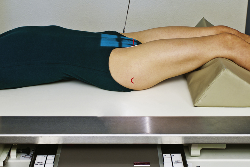
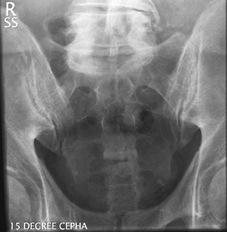
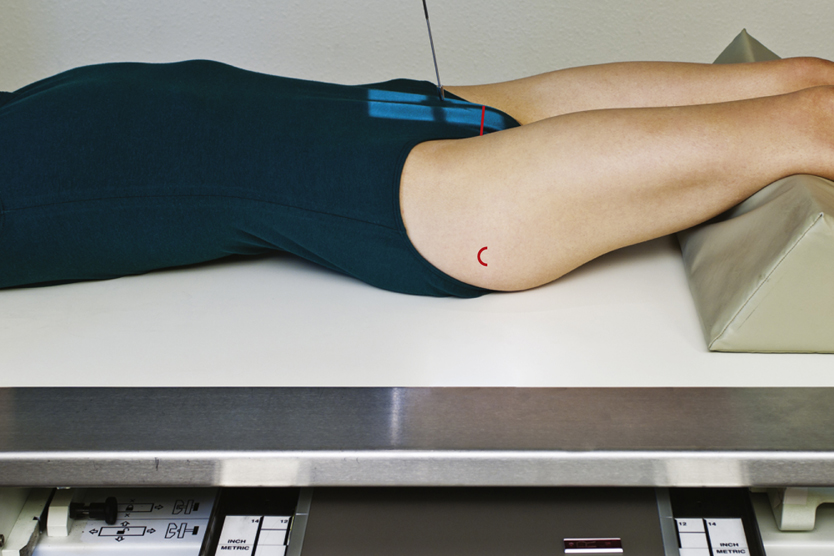
AP Axial Projection—Sacrum
Clinical Indications
NOTE:The urinary bladder should be emptied before this procedure begins. It is also desirable to have the lower colon free of gas and fecal material, which may require a cleansing enema, as ordered by a physician.
Technical Factors

Shielding
Shield radiosensitive tissues outside region of interest.
Patient Position—Supine Position
Position patient supine with arms at side, head on pillow, and legs extended with support under knees for comfort.
Part Position
- • Align midsagittal plane to CR and midline of table and/or IR (Fig. 9.64).
- • Ensure that no rotation of the pelvis exists.
CR
Recommended Collimation
Collimate on four sides to anatomy of interest.
Respiration
Suspend respiration to limit patient motion.
NOTES:Technologist may have to increase CR angle to 20° cephalad for patients with an apparent greater posterior curvature or tilt of the sacrum and pelvis.
Female sacrum is generally shorter and wider than male sacrum (a consideration in close four-sided collimation).
This projection also may be performed prone (angle 15° caudad) if necessary for patient’s condition.
AP Axial Projection—Coccyx
Clinical Indications
NOTE:The urinary bladder should be emptied before this procedure begins. It is also desirable to have the lower colon free of gas and fecal material, which may require a cleansing enema, as ordered by a physician.
Technical Factors

Shielding
Shield radiosensitive tissues outside region of interest.
Patient Position—Supine Position
Position patient supine with arms at side and head on pillow and legs extended with support under knees for comfort.
Part Position
- • Align midsagittal plane to midline of table and/or IR (Fig. 9.67).
- • Ensure that no rotation of the pelvis exists.
CR
Recommended Collimation
Collimate on four sides to anatomy of interest.
Respiration
Suspend respiration to limit patient motion.
NOTES:Technologist may have to increase CR angle to 15° caudad with a greater anterior curvature of the coccyx if apparent by palpation or as evidenced on the lateral.
This projection also may be performed prone (angle 10° cephalad) if necessary for patient’s condition, with CR centered to the coccyx, which can be localized using the greater trochanter.
Lateral Position—Sacrum and Coccyx
Clinical Indications
NOTE:The sacrum and coccyx are commonly imaged together. Separate AP projections are required because of different CR angles, but the lateral projection can be obtained with one exposure centering to include both the sacrum and coccyx. This projection is recommended to decrease gonadal doses.
Technical Factors

Shielding
Shield radiosensitive tissues outside region of interest.
Patient Position—Lateral Position
Place patient in the lateral recumbent position, with head on pillow, and knees flexed.
Part Position
CR
Recommended Collimation
Collimate on four sides to anatomy of interest.
Respiration
Suspend respiration to limit patient motion.
NOTE:High amounts of secondary and scatter radiation are generated. Close collimation is essential to reduce patient dose and obtain a high-quality image.


AP Axial Projection—Sacroiliac Joints
Clinical Indications
Technical Factors

Shielding
Shield radiosensitive tissues outside region of interest.
Patient Position—Supine Position
Position patient supine with arms at side, head on pillow, and legs extended with support under knees for comfort.
Part Position
- • Align midsagittal plane to CR and midline of table and/or IR (Fig. 9.72).
- • Ensure that no rotation of pelvis exists.
CR
Recommended Collimation
Collimate on four sides to anatomy of interest.
Respiration
Suspend respiration to limit patient motion.
Alternative PA axial projection
If patient cannot assume the supine position, this image can be obtained as a PA projection with patient prone, using a 30° to 35° caudad angle. The CR would be centered to the level of L4 or slightly above the iliac crest.


Posterior Oblique Positions (Lpo and Rpo)—Sacroiliac Joints
Clinical Indications
Technical Factors

Shielding
Shield radiosensitive tissues outside region of interest.
Patient Position—Supine Position
Position patient supine with arms at side and head on pillow.
Part Position
- • Rotate body into 25° to 30° posterior oblique, with side of interest elevated (LPO for right joint and RPO for left joint) (Figs. 9.75 and 9.76).
- • Align joint of interest to CR and midline of table and/or IR.
- • Use an angle-measuring device to ensure correct and consistent angles on both oblique positions.
- • Place support under elevated hip and flex elevated knee.
CR
- • CR perpendicular to IR (Fig. 9.77).
- • Direct CR 1 inch (2.5 cm) medial to upside ASIS (see NOTE for optional cephalad angle).
- • Center IR to CR.
Recommended Collimation
Collimate on four sides to anatomy of interest.
Respiration
Suspend respiration to limit patient motion.
NOTE:To demonstrate the inferior or distal part of the joint more clearly, the CR may be angled 15° to 20° cephalad.


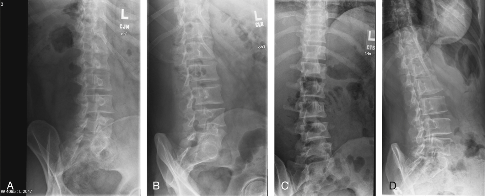
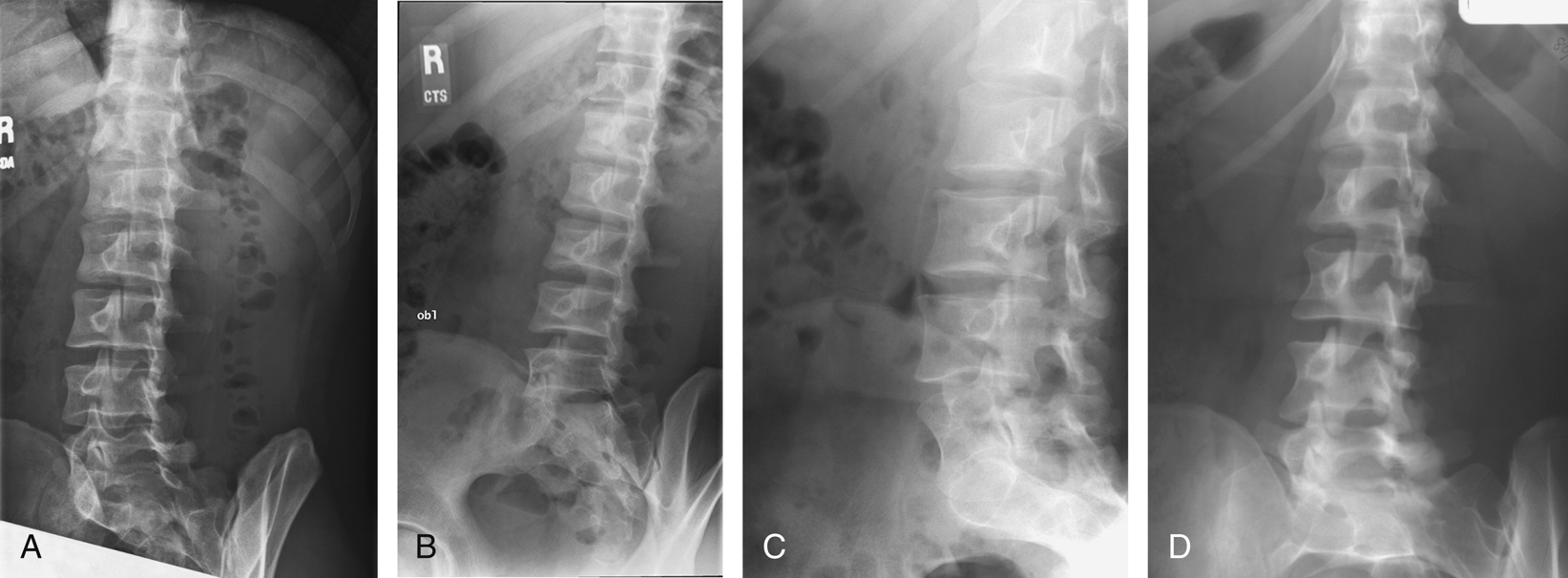
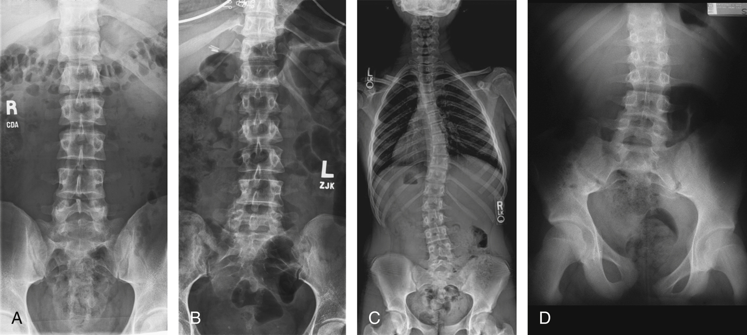
Radiographs for Critique
This section consists of an ideal projection (Image A) along with one or more projections that may demonstrate positioning and/or technical errors. Critique Figs. C9.79 through C9.83 Compare Image A to the other projections and identify the errors. While examining each image, consider the following questions:
- 1. Is all essential anatomy demonstrated on the image?
- 2. What positioning errors are present that compromise image quality?
- 3. Are technical factors optimal?
- 4. Is there evidence of collimation and are pre-exposure anatomic side markers visible on the image?
- 5. Do these errors require a repeat exposure?