CHAPTER 10: Bony Thorax—Sternum and Ribs
Contributions By Katrina Lynn Steinsultz, RT (R)(M), M.Adm, MPH, Contributors to Past Editions John P. Lampignano, MEd, RT(R)(CT), Patti Ward, PhD, RT(R), and Cindy Murphy, BHSc, RT(R), ACR
Radiographic Anatomy
Bony Thorax
The main function of the bony thorax is to serve as an expandable, bellows-like chamber, wherein the interior capacity expands during inspiration and contracts during expiration. These acts of respiration are created by the synchronous work of muscles attached to the rib cage and atmospheric pressure, resulting in air moving into and out of the lungs during respiration.
The bony thorax consists of the sternum anteriorly, the thoracic vertebrae posteriorly, and the 12 pairs of ribs that connect the sternum to the vertebral column. This chapter focuses on the sternum and the ribs; details for the thoracic vertebrae are discussed in Chapter 8. The bony thorax also serves to protect important organs of the respiratory system and vital structures within the mediastinum, such as the heart and great vessels.
Fig. 10.1 demonstrates the relationship of the sternum to the 12 pairs of ribs and the 12 thoracic vertebrae. The thin sternum is superimposed by the structures within the mediastinum and the dense thoracic spine in a direct frontal position. Therefore, any anteroposterior (AP) or posteroanterior (PA) projection radiograph would demonstrate the thoracic spine but would show the sternum minimally, if at all.
Sternum
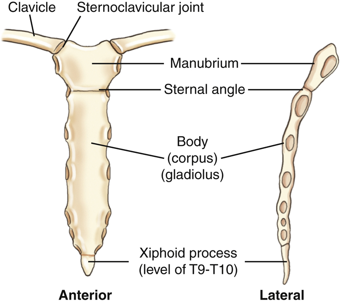
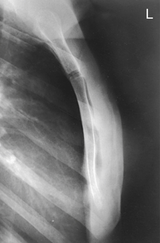
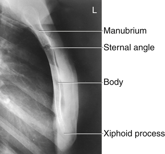
The adult sternum is a thin, narrow, flat bone with three divisions, the manubrium, body, and xiphoid process (Fig. 10.2). The total length of the adult sternum is approximately 7 inches (18 cm). It is composed of highly vascular cancellous tissue covered by a thin layer of compact bone. This vascular cancellous tissue allows for the sternum to be a common site for marrow biopsy, in which, under local anesthesia, a needle is inserted into the medullary cavity of the sternum to withdraw a sample of red bone marrow.
The upper portion is the manubrium (mah-nu′-bre-um). The adult manubrium averages 2 inches (5 cm) in length. The longest part of the sternum is the body, which is about 4 inches (10 cm) long. At birth, the body of the sternum is in four separate segments. The union of these four segments begins during puberty and may not be complete until about the age of 25 years.
The most inferior portion of the sternum is the xiphoid (zi′-foid) process. This is composed of cartilage during infancy and youth. It does not become totally ossified until about the age of 40 years. The xiphoid process generally is rather small; however, it can vary in size, shape, and degree of ossification.
Ribs
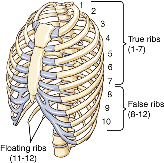
Each rib is numbered according to the thoracic vertebra to which it attaches; therefore, the ribs are numbered from the top down. The first seven pairs of ribs are considered true ribs. True ribs are those ribs that connect directly to the sternum with a short piece of cartilage, called costocartilage. The term false ribs applies to the last five pairs of ribs, numbered 8 through 12. All of the false ribs, except rib pairs 11 and 12, have costalcartilage that join together at the costocartilage of rib 7. The combined costocartilage at rib 7 connects to the sternum. Rib pairs 11 and 12 do not have costocartilage and therefore do not connect to the sternum. The term floating ribs can be used to designate these two pairs of ribs.
The drawing in Fig. 10.3 again clearly shows that, although ribs 8 through 10 have costocartilages, they connect to the costocartilage of the seventh rib.
The last two pairs of false ribs (11 and 12) are unique because they do not possess costocartilage.
Typical Rib
Inferior View
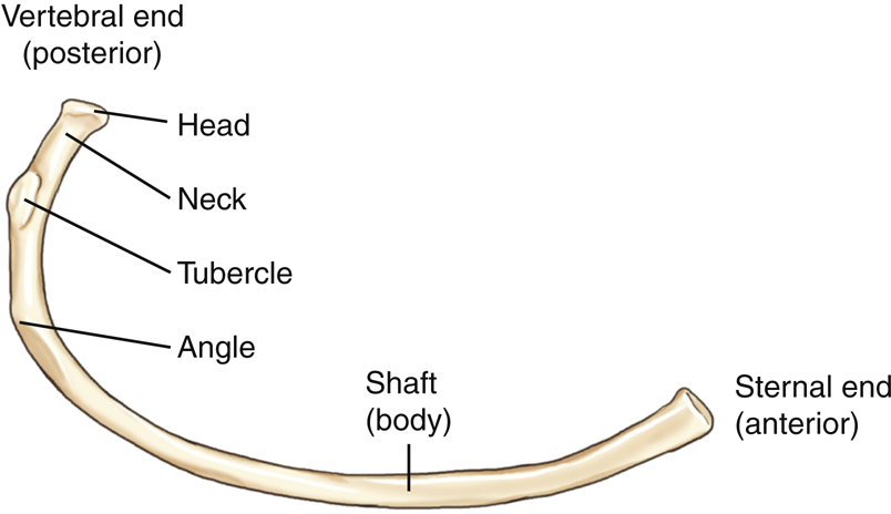
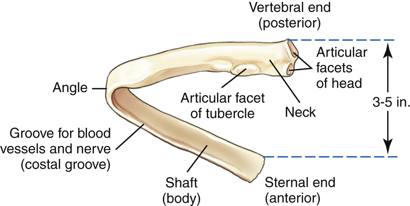
A typical rib viewed from its inferior surface is illustrated in Fig. 10.4. A central rib is used to show the common characteristics of a typical rib. Each rib has two ends, a posterior or vertebral end, which articulates with the thoracic vertebrae and an anterior or sternal end, which articulates with the costocartilage. Between the two ends is the shaft, or body, of the rib.

The vertebral end consists of a head, which articulates with one or two thoracic vertebral bodies, and a flattened neck. Lateral to the neck is an elevated tubercle that articulates with the transverse process of a vertebra and allows for attachment of a ligament. The body extends laterally from the tubercle and then angles forward and downward. The area of forward angulation is termed the angle of the rib (Fig. 10.5).
Posterior view
Fig. 10.5 demonstrates a posterior view of a typical central rib. Seen on this posterior view are the articular facets of the head, the neck, and the articular facets of the tubercle at the vertebral end of the rib. Progressing laterally, the angle of the rib is that part at which the shaft curves forward and downward toward the sternal end.
The posterior or vertebral end of a typical rib is 3 to 5 inches (8 to 13 cm) higher than the anterior or sternal end. Therefore, when viewing a radiograph of a chest or ribs, remember the part of a rib most superior is the posterior end, or the end nearest the vertebrae. The anterior end is more inferior.
The lower inside margin of each rib protects an artery, a vein, and a nerve; therefore, rib injuries are very painful and may be associated with substantial hemorrhage. This inside margin, which contains the blood vessels and nerves, is termed the costal groove.
Rib Cage
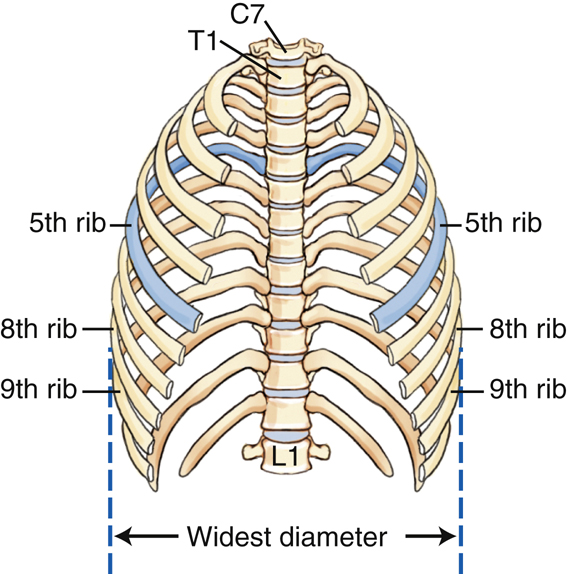
Fig. 10.6 illustrates the bony thorax with the sternum and costocartilage removed. The fifth ribs have been shaded to illustrate the downward angulation of the ribs better.
Not all ribs have the same appearance. The first ribs are short and broad and are the most vertical of all the ribs. Counting downward from the short first pair, the ribs get longer and longer down to the seventh ribs. From the seventh ribs down, they get shorter and shorter through the fairly short twelfth, or last, pair of ribs. The first ribs are the most sharply curved. The bony thorax is typically widest at the lateral margins of the eighth or ninth ribs.
Palpable Landmarks and Articulations of Bony Thorax
Palpable Landmarks
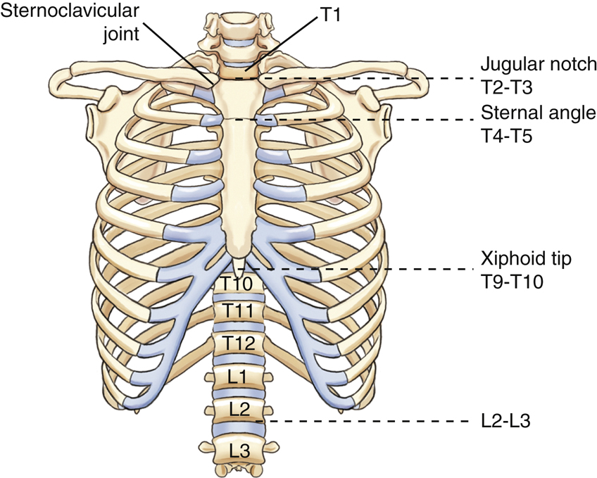
The anterior location and relatively easy palpability of the sternum provide the technologist the ability to locate thoracic and rib structures. The uppermost border of the manubrium has a slightly notched area between the two clavicles, and is easy to visualize and palpate. This area is termed the jugular notch; however, the terms suprasternal notch and manubrial notch are also used. The jugular notch is at the level of T2–T3.
The lower end of the manubrium joins the body of the sternum to form a palpable prominence, the sternal angle (manubriosternal joint). This is also an easily palpated landmark that may be used to locate other structures of the bony thorax. The sternal angle is at the level of the intervertebral disk space between T4 and T5 for an average adult. The xiphoid process corresponds to the level of T9–T10. The inferior rib (costal) angle (inferior costal margin) corresponds to the level of L2–L3 (see Fig. 10.7).
Sternoclavicular Articulation
Each clavicle articulates medially with the manubrium of the sternum at the clavicular notch; this is called the sternoclavicular joint. It is the only bony connection between each shoulder girdle and the bony thorax.
Sternal Rib Articulations
The first seven pairs of ribs connect anteriorly to the sternum through individual sections of costocartilage. The sternum has seven pair of facets, or depressions, located laterally along the manubrium and body to accept the costocartilage. The first pair of facets is located just below the clavicular notch. In Fig. 10.8, the costocartilage and ribs have been added to one side of the drawing to show this relationship.
The second costocartilage connects to the sternum at the level of the sternal angle. An easy way to locate the anterior end of the second rib is to locate the sternal angle first and then feel laterally along the cartilage and the bone of the rib.
The third through the seventh costocartilages connect directly to the body of the sternum.
Ribs 8, 9, and 10 also possess costocartilage, but these connect to costocartilage 7, which then connects to the sternum.
Joint Classifications of Bony Thorax
A frontal view of an articulated thorax is illustrated in Fig. 10.9. The joints or articulations of the anterior bony thorax are identified on this drawing. The joint classifications and types of motion allowed are described as follows (also see Table 10.1):
- Part A demonstrates an example of a costochondral union, or junction, which is a joint between the costocartilage and the sternal end of a rib (shown on left side at the fourth rib). Costochondral unions, found on ribs 1 through 10, are classified as a unique type of union, wherein the cartilage and bone are bound together by the periosteum of the bone itself. This joint permits no motion; therefore, they are termed synarthrodial.
- Part B demonstrates an example of one sternoclavicular joint, which occurs between a clavicle and the manubrium of the sternum. The sternoclavicular joints are synovial joints, containing articular capsules that permit a plane motion, or gliding motion, and are therefore termed diarthrodial joints.
- Part C illustrates the sternocostal joint of the first rib. The cartilage of the first rib attaches directly to the manubrium with no synovial capsule (unlike the sternocostal joints of ribs 2 through 7) and allows no motion (termed synarthrodial). Therefore, this is a cartilaginous class joint of the synchondrosis type.
- Part D demonstrates an example of a sternocostal joint, typical of the second through seventh joints between costocartilage and sternum. These are synovial joints, which allow a slight plane (gliding) motion, making them what is termed diarthrodial joints.
- Part E represents the continuous borders of the interchondral joints between the costal cartilages of the anterior sixth through ninth ribs. These are all interconnected by a synovial type of joint, with a long, thin, articular capsule lined by synovial membrane. These allow a slight plane (gliding) type of movement (diarthrodial), facilitating movement of the bony thorax during the breathing process. Interchondral joints between the ninth and tenth cartilages are not synovial and are classified as fibrous syndesmosis.
Posterior Articulations
The posterior types of joints in the bony thorax, parts F and G, are illustrated in Fig. 10.10. The joints between the ribs and the vertebral column, the costotransverse joints (F) and the costovertebral joints (G), are synovial joints with articular capsules lined by synovial membrane, which allow a plane or gliding motion, and are therefore diarthrodial. Costotransverse joints are found on the first through the tenth ribs. The eleventh and twelfth ribs lack this joint (see Table 10.1).
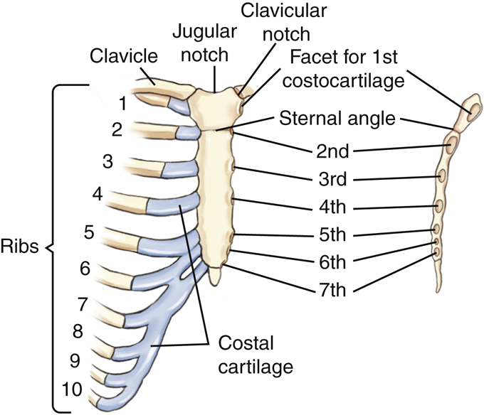
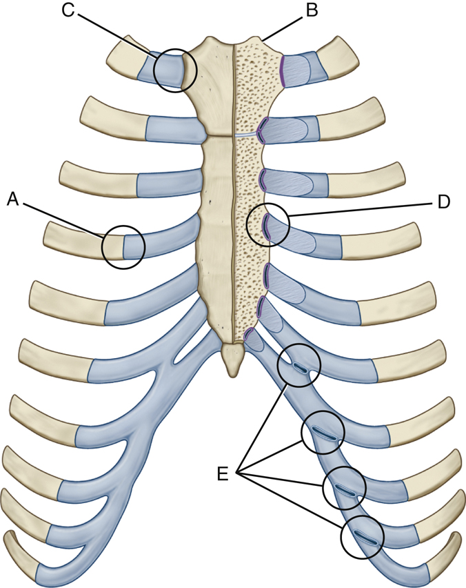

TABLE 10.1

Radiographic Positioning
Positioning Considerations for the Sternum
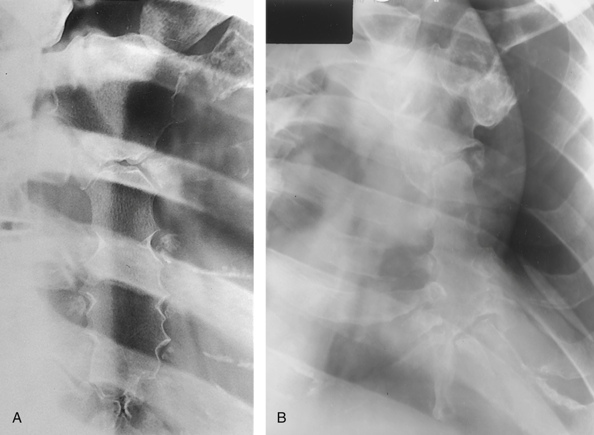
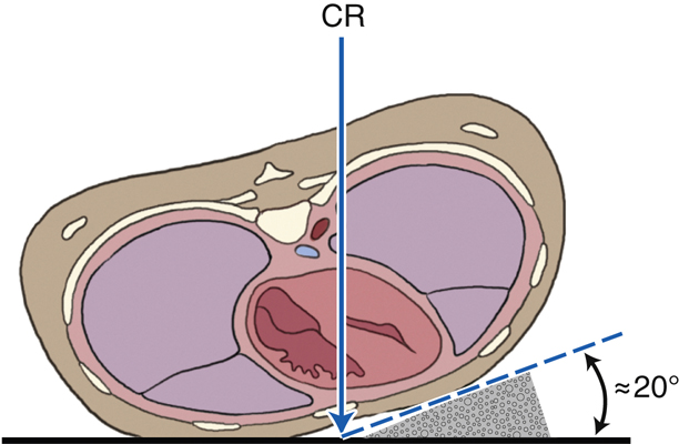
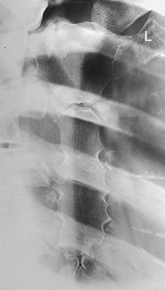
The sternum is difficult to radiograph because of its thin bony cortex and position within the thorax. It is an anterior midline structure that is in the same plane as the thoracic spine. Because the thoracic spine is more dense than the sternum, it is almost impossible to see the sternum in a true AP or PA projection. Therefore, the patient is rotated in a 15° to 20° right anterior oblique (RAO) position to shift the sternum just to the left of the thoracic vertebrae and over the homogeneously dense heart (Fig. 10.11). By rotating the patient and superimposing the sternum over the heart, the outline of the sternum is more easily recognized.
The degree of obliquity required is dependent on the size of the thoracic cavity. A patient with a shallow or thin chest requires more rotation than a patient with a deep chest to cast the sternum away from the thoracic spine. For example, a patient with a large, barrel-chested thorax with a greater AP measurement requires less rotation (≈15°), whereas a thin-chested patient requires more rotation (≈20°). This principle is illustrated in Figs. 10.11 and 10.12.
Exposure Factors
It is difficult to obtain an optimally uniform radiographic appearance of brightness and contrast on sternum images. The sternum is made up primarily of spongy bone with a thin layer of hard compact bone surrounding it. This feature, combined with the close proximity of the easy-to-penetrate lungs and the harder-to-penetrate mediastinum-heart, makes exposure factor selection a challenge. A kVp range of 70 to 85 is recommended for adult sthenic patients to achieve acceptable contrast on the image. Even with optimal exposure factors and patient positioning, the sternum examination results in a low-contrast image making the sternum difficult to visualize (Fig. 10.13).
A breathing technique may be used for radiographic examination of the sternum. A breathing technique involves the patient taking shallow breaths during the exposure. This technique is also referred to as an orthostatic technique. If performed properly, the lung markings overlying the sternum will become blurred, whereas the image of the sternum will remain sharp and well defined (see Fig. 10.13). This requires a medium kVp range (70 to 80) range, a low mA, and a long exposure time, from 3 to 4 seconds. The technologist must be sure the thorax in general is not moving during the exposure, other than from the gentle breathing motion.
Source–Image Receptor Distance (SID)
A minimum SID for sternum radiography is 40 inches (100 cm). In the past, a common practice was to lower the SID to create magnification of the overlying posterior ribs and sternum with resultant unsharpness (blurring). Although this produced a more visible but distorted image of the sternum, it also resulted in an increase in radiation exposure to the patient. Therefore, this practice is not recommended. To minimize dose to the patient, the patient’s skin should be at least 15 inches (40 cm) from the surface of the collimator.
1
Collimation
Proper collimation is important when imaging the sternum. Because this examination typically results in low-contrast images, scatter must be eliminated as much as possible. Collimation to the sternum will reduce the amount of scattered radiation produced, thereby improving image contrast.


Positioning Considerations for the Sternoclavicular Joints
PA Versus AP
Sternoclavicular joint projections are typically performed PA, rather than AP, which can be challenging for the technologist. In the AP projection, the sternoclavicular joints are more easily located. However, PA projections provide the least amount of magnification distortion and reduce the amount of radiation reaching the patient’s thyroid.
Positioning Considerations for the Ribs
Specific projections performed in a radiographic examination of the ribs are determined by the patient’s clinical history and department protocol. If the patient’s history is not provided by the referring physician, the technologist must obtain a complete clinical history that includes the following:
The following positioning guidelines will enable the technologist to produce a diagnostic radiologic examination of the ribs.
Above or Below Diaphragm
The location of the trauma and/or patient complaint determines which region of the ribs is to be imaged. Ribs above the diaphragm require different exposure factors, different breathing instructions, and generally different body positions than ribs located below the diaphragm.
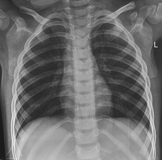
The upper nine posterior ribs generally represent the minimum number of ribs above the dome or central portion of the diaphragm on full inspiration, as described in Chapter 2. However, with painful rib injuries, the patient may not be able to take as deep an inspiration; thus, only eight posterior ribs may be seen above the diaphragm on inspiration.
SID
A minimum SID of 40 inches (100 cm) should be used for all rib studies. Some departments require a 72-inch (180-cm) SID for rib studies to minimize magnification (distortion) of the thorax and reduce skin dose.
Exposure Factors
A medium kVp range is optimal for rib images and allows for penetration of the more dense aspects of the bony thorax while preserving the proper radiographic contrast needed. Use of automatic exposure control (AEC) is not recommended due to the lack of uniformity of tissue density within the bony thorax region.
Above Diaphragm
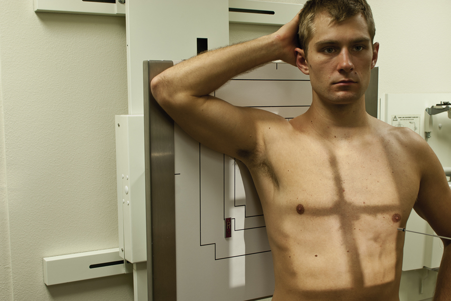
To demonstrate the above-diaphragm ribs best, the technologist should do the following:
- 1. Take the radiographs erect (Fig. 10.14), if the patient is able to stand or sit. Gravity assists in lowering the diaphragm when the patient is in the erect position. This position also allows a deeper inspiration, which depresses the diaphragm to its lowest position. Also, rib injuries are very painful and body movement that creates pressure against the rib cage, such as movement on the x-ray table, can cause severe pain and discomfort.
- 2. Suspend respiration and expose on deep inspiration. This should project the diaphragm below the ninth or tenth ribs on full inspiration.
- 3. Select optimal kVp range (70 to 85 kVp). Because the upper ribs are surrounded by lung tissue, a lower kVp will preserve radiographic contrast and will allow visualization of the ribs through the air-filled lungs. However, if the site of injury is over the heart area, a higher kVp may be used to obtain a longer scale contrast to visualize ribs through the heart shadow and through the lung fields.
Below Diaphragm
To demonstrate these ribs below the diaphragm best, the technologist should do the following:
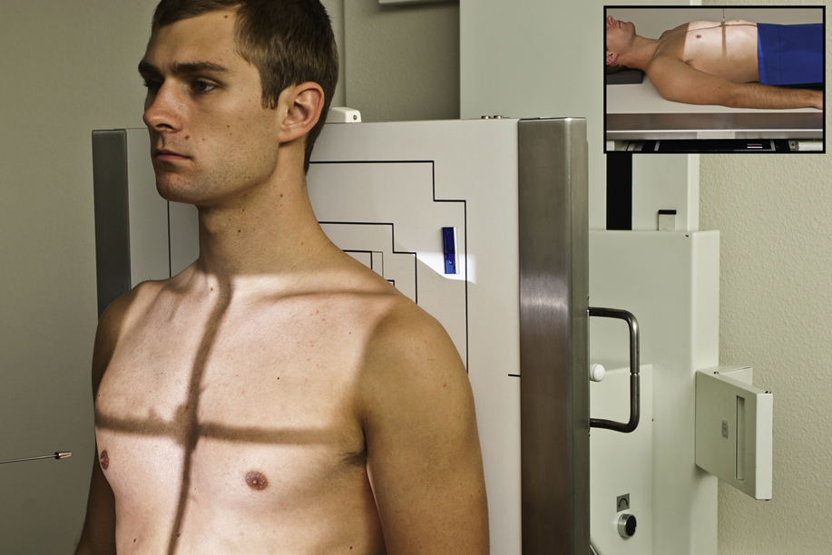
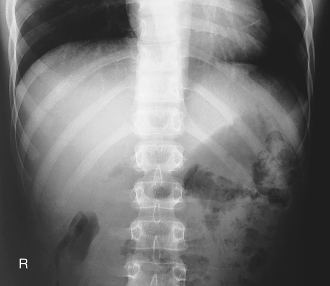
- 1. Take the radiographs with the patient recumbent (supine) (Fig. 10.15). This allows the diaphragm to rise to the highest position and results in a less thick abdomen (especially on hypersthenic patients, because the abdomen flattens when recumbent). This provides better visualization of the lower ribs through abdominal structures.
- 2. Suspend respiration and expose on expiration. This should allow the diaphragm to rise to the level of the seventh or eighth posterior ribs, again providing a uniform density for below-diaphragm ribs.
- 3. Select an optimal kVp (75 to 85). Because the lower ribs are surrounded by the muscular diaphragm and dense abdominal structures, a medium kVp will ensure proper penetration of these tissues.


Recommended Projections
Departmental routines for ribs may vary depending on the preference of radiologists. One recommended routine is as follows.
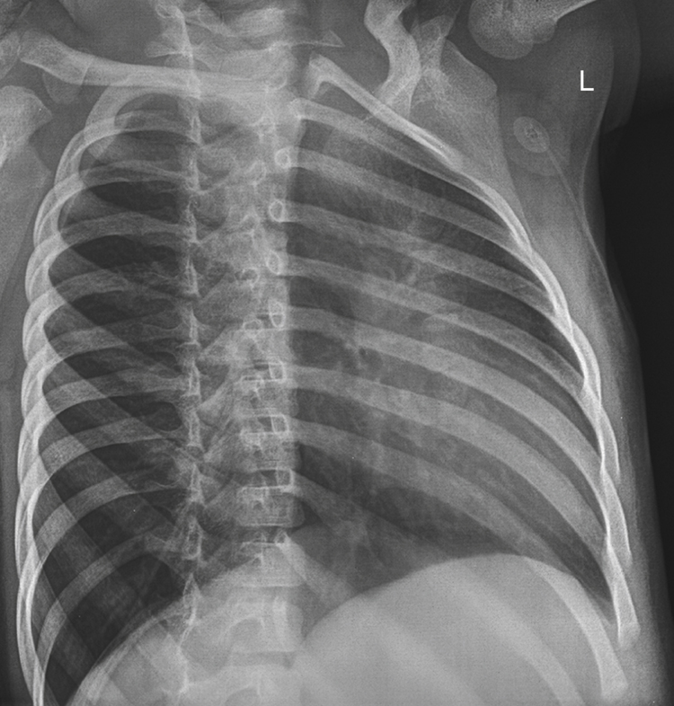
Select the two projections that will place the area of interest closest to the image receptor and rotate the spine away from the area of interest (prevents the spine from superimposing the region of interest and better demonstrates the axillary portion of the involved region of ribs). For example, if a patient has a history of trauma to the left posterior ribs, the two preferred projections with this routine are a straight AP and a left posterior oblique (LPO). (An above- or below-diaphragm technique would be determined by the level of the injured ribs.) The LPO (Fig. 10.16) will move the spinous processes away from the left side. The left posterior ribs are closest and parallel to the IR to increase visibility of this portion of the ribs.
A second example is a patient who has trauma to the right anterior ribs. Two preferred projections are a straight PA and a left anterior oblique (LAO). The PA will place the site of injury closest to the image receptor (IR), and the LAO will rotate the spinous process away from the site of trauma while demonstrating the axillary portion of the right ribs better.
Marking the Site of Injury
Some department protocols request the technologist tape a small metallic BB or some other small type of radiopaque marker over the site of injury before obtaining the images. This ensures that the radiologist is aware of the location of the trauma or pathology as indicated by the patient.
NOTE: Each technologist should determine department protocol on this practice before using this method of identifying the potential site of injury.
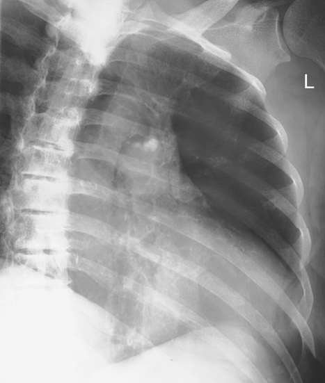
Chest Radiography
Departmental protocols also differ concerning the inclusion of a chest study as part of a rib examination. Trauma to the bony thorax may result in injury to the respiratory system, and patients with a history of rib injuries may require erect PA and lateral projections of the chest and/or inspiration/expiration projections to rule out a possible pneumothorax, hemothorax, pulmonary contusion, or other chest pathology (Fig. 10.17). If the patient cannot assume an erect position and the presence of air-fluid levels must be ruled out, an image obtained with a horizontal beam with the patient in a decubitus position should be included. This is described in Chapter 2.
Special Patient Considerations
Pediatric Applications
Two primary concerns in pediatric radiography are patient motion and safety. A clear explanation of the procedure is required to obtain maximal trust and cooperation from the patient and guardian.
Careful immobilization is important to achieve proper positioning and to reduce patient motion. A short exposure time with optimal mA and kVp help reduce patient motion. To secure their safety, ensure that pediatric patients are continuously watched and cared for.
Communication
A clear explanation of the procedure is required to obtain maximum trust and cooperation from the patient and guardian. Distraction techniques that use, for example, toys or stuffed animals are also effective in maintaining patient cooperation.
Immobilization
Pediatric patients (depending on age and condition) are often unable to maintain the required position. Use of an immobilization device to support the patient is recommended to reduce the need for the patient to be held, thus reducing radiation exposure. (Chapter 16 provides an in-depth description of these devices.) If the patient must be held by the guardian, the technologist must provide a lead apron and/or gloves and, if the guardian is female, must ensure no possibility of pregnancy.
Exposure Factors
Exposure factors will vary as a result of various patient sizes. Use of short exposure times (associated with the use of high mA) is recommended to reduce the risk for patient motion. A breathing technique is not indicated for the young pediatric patient.
Collimation
When possible, collimate to the involved region and reduce exposure to the thyroid gland and other radiosensitive structures.
Geriatric Applications
Communication and Comfort
Sensory losses (e.g., eyesight, hearing) associated with aging may result in the need for additional assistance, time, and patience in helping the older patient achieve the required positions for the sternum and ribs. Decreased position awareness may cause these patients to fear falling off the radiography table when they are imaged in the recumbent position. Reassurance and additional care from the technologist will enable the patient to feel secure and comfortable.
If the examination is performed with the patient in the recumbent position, a radiolucent mattress or pad placed on the examination table will provide comfort. Extra blankets also may be required to keep the patient warm.
Exposure Factors
Because of the high incidence of osteoporosis in older patients, the kVp or mAs may require a decrease if manual exposure factors are used with analog imaging. Older patients may have tremors or difficulty holding steady. Use of short exposure times (associated with the use of high mA) is recommended to reduce the risk for motion.

Bariatric Patient Considerations
The bariatric patient does present some unique challenges in imaging of the bony thorax. Landmarks such as the xiphoid process, sternal angle, and vertebra prominens (spinous process of C7) may be difficult to palpate. The easiest landmark to locate through palpation is the jugular notch. Use this landmark for sternum and rib positioning to determine the upper border of the sternum, SC joints, and ribs. The iliac crest or lower costal angle can be used as a landmark to indicate the lower margin of the ribs.
Although the thorax region looks larger in the bariatric patient than in the sthenic patient, it is important to remember the thoracic structures are often the same dimensions. Maintain the same degree of collimation for sternum and rib projections as with other body sizes. Do not set the field size larger than the size of the IR being used. The sternum and SC joint projections can still be performed with a 10 × 12-inch (24 × 30-cm) IR.
Because of the thickness of the anatomy, it is important to use a grid (bucky) for all procedures to decrease scatter radiation reaching the image receptor. This is especially important when performing mobile procedures for studies of the bony thorax. Manual exposure factors may need to be adjusted because of the size of the patient. However, the kVp should be set as high as appropriate while keeping the mAs low to minimize radiation dose to the patient.
Digital Imaging Considerations
Guidelines for digital imaging (computed radiography and digital radiography [DR]) of the bony thorax, sternum, and ribs are similar to those described in previous chapters. These include the following:
- 1. Correct study and projections selected.
- 2. Centering and four-sided collimation (especially for sternum projections).
- 3. Apply ALARA principle (as low as reasonably achievable) in determining exposure factors (may be desirable to increase kVp and decrease mAs for reducing patient exposure.)
- 4. Post-processing evaluation of exposure indicator (for highest quality image with least amount of radiation to the patient). Based on the exposure indicator and department standards, this determines whether a reduction in mAs is possible for future and repeat exposures.
Alternative Modalities and Procedures
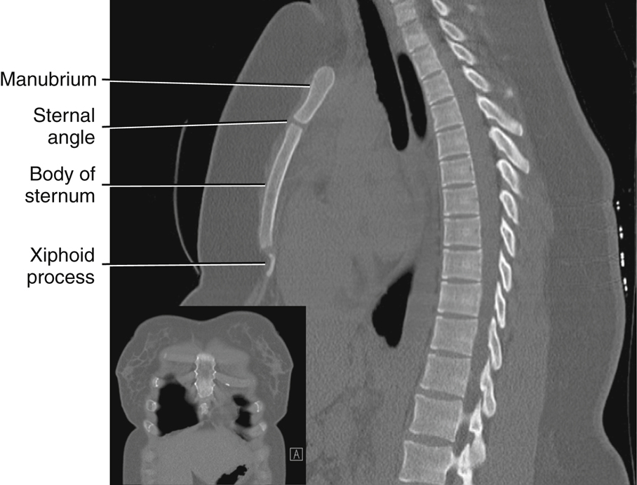
Computed Tomography
Computed tomography (CT) provides sectional images of the bony thorax. Skeletal detail and associated soft tissues may be evaluated with CT when clinically indicated. CT is useful for visualizing pathology involving the sternum (Fig. 10.18) and/or sternoclavicular joints without obstruction by overlying dense structures (Fig. 10.19).
Nuclear Medicine
Nuclear medicine (NM) provides a sensitive diagnostic procedure (radionuclide bone scan) for detection of skeletal pathologies of the thoracic cage (e.g., metastases, occult fractures). A radiopharmaceutical-tagged tracer element is injected, which will concentrate in areas of increased bone activity, demonstrating a hot spot on the nuclear medicine image. Any abnormal area then is investigated further with radiography.
It is common practice for patients who are at risk of or symptomatic for skeletal metastases to undergo a bone scan; patients with multiple myeloma are exceptions to this.

Clinical Indications
- Fractures: The word fracture refers to a break in the structure of a bone. Fractures of the bony thorax can be particularly dangerous because of the proximity of the lungs, heart, and great vessels. Areas of common fracture include the following:
-
- • Ribs: Rib fractures are most commonly caused by trauma or underlying pathology. Any rib fracture may cause injury to the lung or cardiovascular structures (e.g., pneumothorax, pulmonary or cardiac contusion). In particular, fractures to the first rib often are associated with injury to the underlying arteries or veins, whereas fractures to the lower ribs (9 to 12) may be associated with injury to adjacent organs such as the spleen, liver, or kidney.
- • Flail chest: This fracture of adjacent ribs in two or more places is caused by blunt trauma and is associated with underlying pulmonary injury. This type of injury can lead to instability of the chest wall. If the technologist suspects a flail chest injury, perform rib studies erect if the patient’s condition permits it for best visualization.
- • Sternum: Typically caused by blunt trauma, fractures of the sternum are associated with underlying cardiac injury.
- Congenital anomalies: Congenital anomalies are conditions present from birth that may become more evident as a child ages.
-
- • Pectus carinatum (pigeon breast): This defect is characterized by anterior protrusion of the lower sternum and xiphoid process. It is usually a benign condition but could lead to cardiopulmonary complications in rare cases.
- • Pectus excavatum: Also referred to as funnel chest, this deformity is characterized by a depressed sternum. This condition rarely interferes with respiration but often is corrected surgically for cosmetic reasons.
- Metastases: These primary malignant neoplasms spread to distant sites via blood and lymphatics. The ribs are common sites of metastatic lesions, which may be characterized and visualized on the image as follows:
- Osteomyelitis: This localized or generalized infection of bone and marrow can be associated with postoperative complications of open heart surgery, which requires the sternum to be split. The most common cause of osteomyelitis is a bacterial infection.
See Table 10.2 for a summary of clinical indications.
Routine and Special Projections
Protocols and positioning routines vary among facilities, depending on administrative structures, liabilities, and other factors. All technologists should become familiar with the current standards of practice, protocols, and routine or basic and special projections for any facility in which they are working.
Certain routine and special projections for the sternum, sternoclavicular joints, and ribs are demonstrated and described on the following pages as suggested standard routine and special departmental routines or procedures.
TABLE 10.2
| Condition or Disease | Most Common Radiographic Examination | Possible Radiographic Appearance | Exposure Factor Adjustment a |
|---|---|---|---|
| Fractures | |||
| Ribs—flail chest | Routine radiographic views of the ribs and chest. Perform study erect when possible | Disruption of bony cortex of the rib; linear lucency through the rib | None |
| Sternum | Routine radiographic sternum views, computed tomography | Disruption of bony cortex of the sternum; linear lucency or a displaced sternal segment | None |
| Congenital Anomalies | |||
| Pectus carinatum (pigeon breast) | Routine chest and possible lateral sternum | Anterior protrusion of lower sternum | None |
| Pectus excavatum (funnel chest) | Routine chest and possible lateral sternum | Depressed sternum | None |
| Metastases | Routine radiographic views, nuclear medicine bone scan | Depends on lesion type: • Osteolytic: irregular margins and decreased density • Osteoblastic lesions: increased density • Combination—moth-eaten appearance |
Lesion type: • Osteolytic: decrease (−) • Osteoblastic: increase (+) • Combination: none |
| Osteomyelitis | Routine sternum views, nuclear medicine bone scan | Erosion of bony margins | None |

RAO Position—Sternum
Clinical Indications
Technical Factors

Shielding
Shield radiosensitive tissues outside region of interest.
Patient Position
Erect (preferred) or semiprone position with slight rotation, right arm down by side, and left arm up.
Part Position

CR
- • CR perpendicular to IR
- • CR directed to center of sternum (1 inch [2.5 cm] to left of midline and midway between the jugular notch and xiphoid process) (Fig. 10.20)
Recommended Collimation
Long, narrow collimation field to region of sternum
Respiration
Orthostatic (shallow breathing) technique can be performed if patient can cooperate. If breathing technique is not possible, suspend respiration on expiration. Orthostatic breathing technique requires a minimum of a 3-second exposure time and a low mA to produce blurring of overlying vascular structures. The orthostatic technique for the RAO sternum projection is most effective for the recumbent patient in whom the sternum is less likely to move during the long exposure. There is a risk of unintentional movement of the body thorax when the position is performed erect.
NOTE 1—Rotation: A large, deep-chested thorax requires less rotation than a thin-chested thorax to shift the sternum just to the left of the vertebral column superimposed over the homogeneous heart shadow. The amount of required rotation also can be determined by placing one hand on the sternum and the other on the spinous processes and determining that these two points are not superimposed, as viewed from the position of the x-ray tube (see Figs 10.11 and 10.12).
NOTE 2—Adaptation: This can be obtained in an LPO position if the patient’s condition does not permit an RAO position. (See Chapter 15 for trauma positions of the sternum.) If the patient cannot be rotated, an oblique image may be obtained by angling the CR 15° to 20° across the right side of the patient to project the sternum lateral to the vertebral column, onto the heart shadow (see Fig. 10.20, inset). A portable grid would be required and should be placed crosswise on the stretcher or tabletop to prevent grid cutoff.


Lateral Position: R or L Lateral—Sternum
Clinical Indications
Technical Factors

Shielding
Shield radiosensitive tissue outside region of interest.
Patient Position
Erect (preferred) or lateral recumbent
Part Position
Erect
- • Position patient standing or seated with shoulders and arms drawn back (Fig. 10.23).
Lateral Recumbent
CR
Recommended Collimation
Long, narrow collimation field, to region of sternum.
Respiration
Suspend respiration on inspiration.
NOTE 1: SID of 60 to 72 inches (150 to 180 cm) is recommended to reduce magnification of sternum caused by increased OID. (If unable to obtain this SID and if a minimum of 40 inches [100 cm] is used, a larger IR of 14 × 14 inches [35 × 35 cm] is recommended to compensate for the magnification.)
NOTE 2: Large, pendulous breasts of female patients may be drawn to the sides and held in position with a wide bandage if necessary.
Adaptation
The lateral image can be obtained with the use of a horizontal x-ray beam with patient in the supine position if patient’s condition warrants this modification (Fig. 10.24).


PA Projection—Sternoclavicular Joints
Clinical Indications
Technical Factors

Shielding
Shield radiosensitive tissues outside region of interest.
Patient Position
Patient prone, chin resting on radiolucent positioning sponge, arms up beside head or down by side (Fig. 10.27). Projection may also be taken erect.
Part Position
CR
Recommended Collimation
Collimate to region of sternoclavicular joints (approximately 2 inches (5 cm) on either side of the thoracic spine).
Respiration
Suspend on expiration for a more uniform density.


Anterior Oblique Positions: RAO and LAO—Sternoclavicular Joints
Images of the right and left joints are obtained
Clinical Indications
Technical Factors

Shielding
Shield radiosensitive tissues outside region of interest.
Patient Position
Prone or erect with slight rotation (10° to 15°) of thorax with upside elbow flexed and hand placed adjacent to head
Part Position
- • With patient rotated 10° to 15°, align and center spinous process 1 to 2 inches (3 to 5 cm) lateral (toward upside) to CR and midline of grid or table/upright bucky (Fig. 10.30).
- • Center IR to CR
CR
Recommended Collimation
Collimate to region of sternoclavicular joints.
Respiration
Suspend on expiration for a more uniform density (brightness).
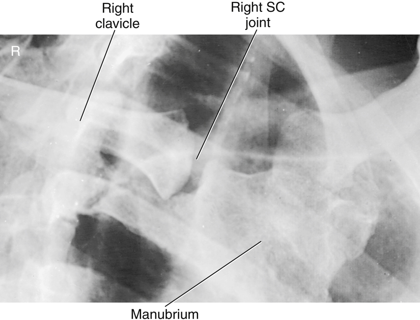
NOTE 1: A 10° to 15° rotation in an anterior oblique position will rotate the SC joint across the spine to the opposite lung field, thus demonstrating the downside SC joint. An RAO best demonstrates the right SC joint in the left lung field (Fig. 10.31), whereas the LAO position best demonstrates the left SC joint in the right lung field.
NOTE 2: With less obliquity (5° to 10°), the opposite SC joint (the upside joint) would be visualized next to the vertebral column.
Adaptation
(1) If the patient’s condition requires this, oblique images may be obtained by using posterior oblique with 10° to 15° rotation with the CR 1 to 2 inches (2.5 to 5 cm) lateral to midsagittal (toward downside). The upside SC joint would be best visualized in this projection. (2) Oblique images may also be obtained by angling the CR 15° across the patient to project the SC joint lateral to the vertebrae. A portable grid would be required and should be placed crosswise on the stretcher or tabletop to prevent grid cutoff.


AP Projection—Bilateral Posterior Ribs
Above or Below Diaphragm
Clinical Indications
Technical Factors

Shielding
Shield radiosensitive tissues outside region of interest.
Patient Position
Erect position is preferred for above diaphragm if patient’s condition allows and supine for below diaphragm (Fig. 10.33).
Part Position
CR
Above diaphragm
Below diaphragm
Recommended Collimation
Collimate to region of interest. Below-diaphragm rib images allow for increased collimation.
Respiration
Suspend respiration on deep inspiration for ribs above the diaphragm and on full expiration for ribs below the diaphragm.
NOTE: When performing a bilateral rib examination, place IR landscape for 40-inch (100-cm) SID and/or for large patients for both above- and below-diaphragm ribs to ensure that lateral rib margins are not cut off. A 72-inch (180-cm) SID also can be used to minimize magnification of the anatomy and may allow the IR to be positioned portrait.
PA Projection—Bilateral Anterior Ribs
Above Diaphragm
Clinical Indications
Injuries to ribs below the diaphragm are generally to posterior ribs; therefore, AP projections are indicated.
Technical Factors

Shielding
Shield radiosensitive tissues outside region of interest.
Patient Position
Erect preferred or prone if necessary, with arms down to the side (Fig. 10.36)
Part Position
CR
Recommended Collimation
Collimate to region of interest.
Respiration
Suspend respiration on inspiration.
NOTE: Use of a 72-inch (180-cm) SID and/or narrow chest dimensions may allow the IR to be positioned portrait.
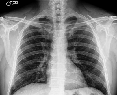
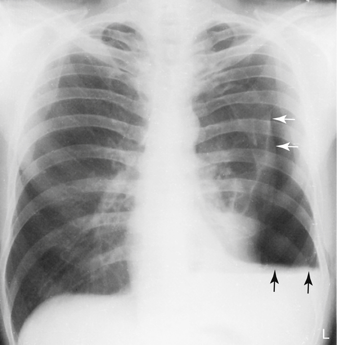
PA erect and lateral chest study
A common rib routine series typically includes an erect PA and (sometimes) lateral chest projections with lung exposure techniques to rule out respiratory trauma or dysfunctions such as pneumothorax (white arrows) or hemothorax (black arrows), which may accompany rib injuries (Fig. 10.37).

AP Projection: Unilateral Rib Study—Posterior Ribs
Above or Below Diaphragm
NOTE: This projection is taken to demonstrate specific trauma to posterior ribs along one side of the thoracic cavity.
Technical Factors

Shielding
Shield radiosensitive tissues outside region of interest.
Patient Position
Erect position is preferred for above diaphragm (Fig. 10.39) if patient’s condition allows or supine for below diaphragm.
Part Position
CR
Above diaphragm
Below diaphragm
- • CR perpendicular to IR, centered midway between midsagittal plane and lateral margin of thorax at a level midway between the xiphoid process and the lower rib margin
- • Align left or right side of thorax to CR and to midline of grid or table/upright bucky.
- • IR centered to CR (bottom of IR at iliac crest)
Recommended Collimation
Collimate to region of interest.
Respiration
Suspend respiration on deep inspiration for ribs above the diaphragm and on full expiration for ribs below the diaphragm.

Anterior Oblique Positions—Axillary Ribs
Above or Below Diaphragm
Clinical Indications
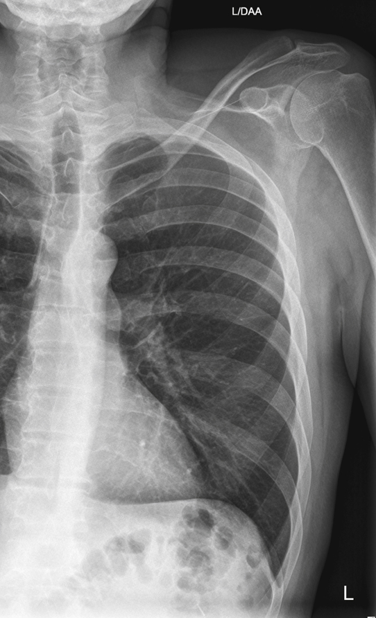
Oblique positions will demonstrate the axillary portion of the ribs that is not well seen on the AP-PA projections.
Technical Factors

Shielding
Shield radiosensitive tissues outside region of interest.
Patient Position
Erect position is preferred for above diaphragm if patient’s condition allows or supine for below diaphragm.
Part Position
- • Rotate patient into 45° posterior or anterior oblique, with affected side closest to IR on posterior oblique and affected side away from IR on anterior oblique. Fig. 10.41 is an RPO, which will demonstrate the axillary portion of the right ribs. Fig. 10.42 is an RAO, which demonstrates the axillary portion of the left ribs. (Hint: rotate spine away from site of injury.)
- • Raise elevated side arm above head; extend opposite arm down and behind patient away from thorax.
- • If recumbent, flex knee of elevated side to help maintain this position.
- • Support body with positioning sponges if needed.
- • Align a plane of the thorax midway between the spine and the lateral margin of thorax on side of interest to CR and to midline of the grid or table/bucky. (Ensure that side of interest is not cut off.)
CR
Above diaphragm
Below diaphragm
- • CR to level midway between xiphoid process and lower rib margin (bottom of IR at about level of iliac crest) (Fig. 10.43)
Recommended Collimation
Collimate to region of interest.


Respiration
Suspend respiration on inspiration for above-diaphragm ribs and on expiration for below-diaphragm ribs.
NOTE: To demonstrate the axillary portion of the right ribs, perform an RPO or LAO position. To demonstrate the axillary portion of the left ribs, perform an LPO or RAO position (Figs. 10.44 and 10.45)
Additional collimated projection
Some departmental routines include one well-collimated projection of the region of injury taken on a smaller IR (Fig. 10.46).


Radiographs for Critique
This section consists of an ideal projection (Image A) along with one or more projections that may demonstrate positioning and/or technical errors. Critique Figures C10.47 through C10.50. Compare Image A to the other projections and identify the errors. While examining each image, consider the following questions:
- 1. Is all essential anatomy demonstrated on the image?
- 2. What positioning errors are present that compromise image quality?
- 3. Are technical factors optimal?
- 4. Is there evidence of collimation and are pre-exposure anatomic side markers visible on the image?
- 5. Do these errors require a repeat exposure?