Chapter 11: Cranium, Facial Bones, and Paranasal Sinuses
Contributions By Michele L. Gray-Murphy, M.Ed., RT(R)(M)(ARRT)
Contributors To Past Editions Kathy M. Martensen, BS, RT(R), Barry T. Anthony, RT(R), Cindy Murphy, BHSc, RT(R), ACR, Renee F. Tossell, PhD, RT(R)(M)(CV), and Mindy S. Shapiro, RT(R)(CT)
Radiographic Anatomy
Skull
As with other body parts, radiography of the skull requires a good understanding of all related anatomy. The anatomy of the skull is very complex, and specific attention to detail is required of the technologist.
The skull, or bony skeleton of the head, rests on the superior end of the vertebral column and is divided into two main sets of bones—8 cranial bones and 14 facial bones (Fig. 11.1). Anatomy and positioning for the cranial and facial bones are described in this chapter.
Cranial Bones
The eight bones of the cranium are divided into the calvarium (skullcap) and the floor. Each of these two areas primarily consists of four bones.
Calvarium (Skullcap)
Floor
The eight bones that make up the calvarium (skullcap) and the floor or base of the cranium are demonstrated on these frontal, lateral, and superior cutaway view drawings (Figs. 11.2, 11.3, and 11.4). These cranial bones are fused in an adult to form a protective enclosure for the brain. Each of these cranial bones is demonstrated and described individually in the pages that follow.


Frontal Bone
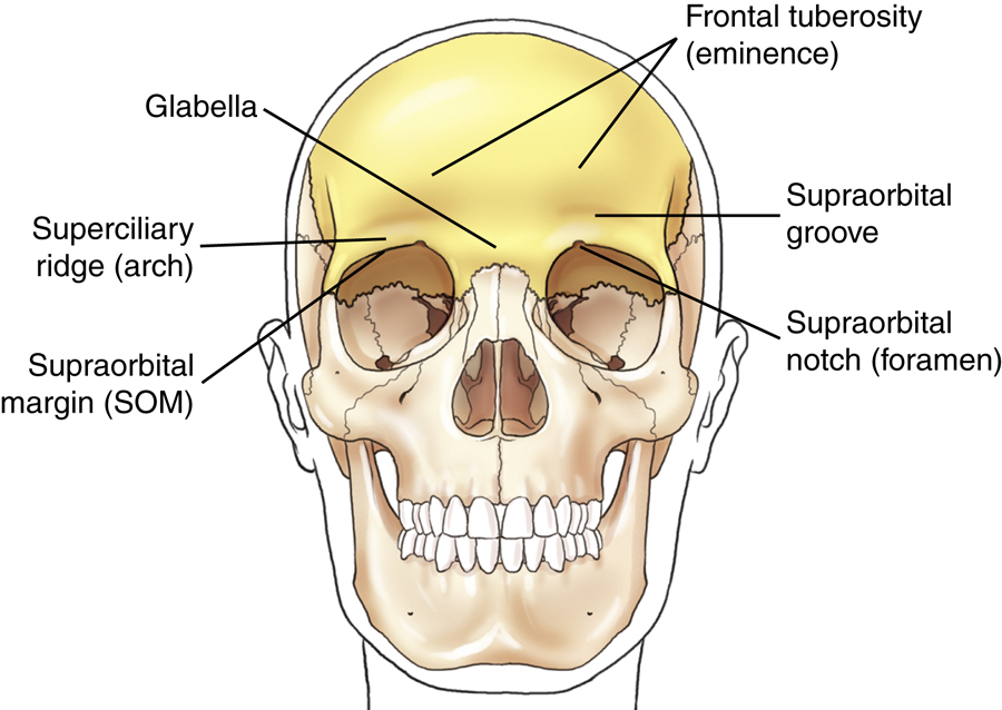
As viewed from the front, the bone of the calvarium that is most readily visible is the frontal bone. This bone contributes to the formation of the forehead and the superior part of each orbit. It consists of two main parts: the squamous or vertical portion, which forms the forehead, and the orbital or horizontal portion, which forms the superior part of the orbit.
Squamous or vertical portion
The glabella is the smooth, raised prominence between the eyebrows just above the bridge of the nose (Figs. 11.5 and 11.6).
The supraorbital groove (SOG) is the slight depression above each eyebrow. The SOG becomes an important landmark because it corresponds to the floor of the anterior fossa of the cranial vault, which is also at the level of the orbital plate or at the highest level of the facial bone mass (Fig. 11.7).
NOTE:You can locate the SOG on yourself by placing your finger against the length of your eyebrow and feeling the raised arch of bone, then allowing your finger to slide upward and drop slightly into the SOG.
The superior rim of each orbit is the supraorbital margin (SOM). The supraorbital notch (foramen) is a small hole or opening within the SOM slightly medial to its midpoint. The supraorbital nerve and artery pass through this small opening.
On each side of the squamous portion of the frontal bone above the SOG is a larger, rounded prominence termed the frontal tuberosity (eminence).
Orbital or horizontal portion
As can be seen from the inferior aspect, the frontal bone shows primarily the horizontal or orbital portion (see Fig. 11.7), which consists of the SOMs, superciliary ridges, glabella, and frontal tuberosities.
The orbital plate on each side forms the superior part of each orbit. Below the orbital plates lie facial bones, and above the orbital plates is the anterior part of the floor of the brain case.
Each orbital plate is separated from the other by the ethmoidal notch. The ethmoid bone, one of the bones of the floor of the cranium, fits into this notch.
Articulations
The frontal bone articulates with four cranial bones: right and left parietals, sphenoid, and ethmoid. These can be identified on frontal, lateral, and superior cutaway drawings in Figs. 11.3 and 11.4. (The frontal bone also articulates with eight facial bones.)


Parietal Bones
The paired right and left parietal bones are well demonstrated on the lateral and superior view drawings of Figs. 11.8 and 11.9. The lateral walls of the cranium and part of the roof are formed by the two parietal bones. The parietal bones are roughly square and have a concave internal surface.
The widest portion of the entire skull is located between the parietal tubercles (eminences) of the two parietal bones. The frontal bone is primarily anterior to the parietals; the occipital bone is posterior; the temporal bones are inferior; and the greater wings of the sphenoid are inferior and anterior.
Articulations
Each parietal bone articulates with five cranial bones: frontal, occipital, temporal, sphenoid, and opposite parietal bones.
Occipital Bone
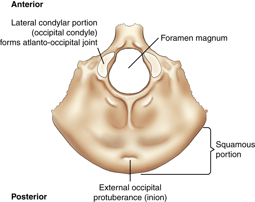
The inferoposterior portion of the calvarium (skullcap) is formed by the single occipital bone. The external surface of the occipital bone presents a rounded part called the squamous portion. The squamous portion forms most of the back of the head and is the part of the occipital bone that is superior to the external occipital protuberance, or inion, which is the prominent bump or protuberance at the inferoposterior portion of the skull (Fig. 11.10).
The large opening at the base of the occipital bone through which the spinal cord passes as it leaves the brain is called the foramen magnum (literally meaning “great hole”).
The two lateral condylar portions (occipital condyles) are oval processes with convex surfaces, with one on each side of the foramen magnum. These articulate with depressions on the first cervical vertebra, called the atlas. This two-part articulation between the skull and the cervical spine is called the atlantoccipital joint. They form a pair of ellipsoid joints that permits flexion, extension and a limited amount of lateral flexion and rotation.
Articulations
The occipital bone articulates with six bones: two parietals, two temporals, sphenoid, and atlas (first cervical vertebra).


Temporal Bones
Lateral view
The paired right and left temporal bones are complex structures that house the delicate organs of hearing and balance. As seen from this lateral view drawing (Fig. 11.11), the left temporal bone is situated between the greater wing of the sphenoid bone anteriorly and the occipital bone posteriorly.
Extending anteriorly from the squamous portion of the temporal bone is an arch of bone termed the zygomatic (zi″-go-mat′-ik) process. This process meets the temporal process of the zygomatic bone (one of the facial bones) to form the easily palpated zygomatic arch.
Inferior to the zygomatic process and just anterior to the external acoustic (auditory) meatus (EAM) is the temporomandibular (TM) fossa, into which the mandible fits to form the temporomandibular joint (TMJ).
Projecting inferior to the mandible and anterior to the EAM is a slender bony projection called the styloid process.
Frontal cutaway view
Each temporal bone is divided into three primary parts (Fig. 11.12). First is the thin upper portion that forms part of the wall of the skull, the squamous portion. This part of the skull is quite thin and is the most vulnerable portion of the entire skull to fracture.
The second portion is the area posterior to the EAM, the mastoid portion, with a prominent mastoid process, or tip. Many air cells are located within the mastoid process.
The third main portion is the dense petrous (pet′-rus) portion, which also is called the petrous pyramid, or pars petrosa; it houses the organs of hearing and equilibrium, including the mastoid air cells, as described later in this chapter. Sometimes this is also called the petromastoid portion of the temporal bone because internally it includes the mastoid portion. The upper border or ridge of the petrous pyramids is commonly called the petrous ridge, or petrous apex.
Superior view
The floor of the cranium is well visualized in this drawing (Fig. 11.13). The single occipital bone resides between the paired temporal bones. The third main portion of each temporal bone, the petrous portion, again is shown in this superior view. This pyramid-shaped portion of the temporal bone is the thickest and densest bone in the cranium. The petrous pyramids project anteriorly and toward the midline from the area of the EAM.
The petrous ridge of these pyramids corresponds to the level of an important external landmark, the TEA (top of the ear attachment). Near the center of the petrous pyramid on the posterior surface just superior to the jugular foramen is an opening or orifice called the internal acoustic meatus, which serves to transmit the nerves of hearing and equilibrium. The bilateral jugular foramina are located in the base of the cranium and are where the internal jugular veins are formed and three cranial nerves (IX, X, and XI) pass.
1
NOTE:The openings of the external and internal acoustic meatus cannot be visualized on this superior view drawing (Fig. 11.13) because they are located on the posteroinferior aspect of the petrous pyramid.
Articulations
Each temporal bone articulates with three cranial bones: parietal, occipital, and sphenoid. (Each temporal bone also articulates with two facial bones.)


Sphenoid Bone
Superior view
The single centrally located sphenoid bone forms the anchor for the other seven cranial bones. The central portion of the sphenoid is the body, which lies in the midline of the floor of the cranium and contains the sphenoid sinus, as is best shown on a sagittal sectional drawing (see Fig. 11.18).
The central depression on the body is termed the sella turcica (sel′-a tur′-si-ka). This depression looks like a saddle from the side (see Fig. 11.16), and it derives its name from words meaning “Turkish saddle.” The sella turcica partially surrounds and protects a major gland of the body, the hypophysis cerebri, or pituitary gland. Posterior to the sella turcica is the back of the saddle, the dorsum sellae (dor′-sum sel′-e) (also best seen in Fig. 11.16).
The clivus (kli′-vus) is a shallow depression that begins on the posteroinferior aspect of the dorsum sellae of the sphenoid bone and extends posteriorly to the foramen magnum at the base of the occipital bone (Fig. 11.14; also see Fig. 11.16). This slightly depressed area forms a base of support for the pons (a portion of the brainstem) and for the basilar artery.
Extending laterally from the body to either side are two pairs of wings. The smaller pair, termed the lesser wings, are triangular and are nearly horizontal, ending medially in the two anterior clinoid processes. They project laterally from the superoanterior portion of the body and extend to the middle of each orbit. The greater wings extend laterally from the sides of the body and form a portion of the floor of the cranium and a portion of the sides of the cranium.
Three pairs of small openings or foramina exist in the greater wings for passage of certain cranial nerves (see Fig. 11.14). Lesions that can cause erosion of these foramina can be detected radiographically. The foramen rotundum (ro-tun′-dum) and the foramen ovale (o-va′-le) are seen as small openings on superior and oblique view drawings (Figs. 11.14 and 11.15). The small rounded foramen spinosum (spi-no′-sum) (one of a pair) is also labeled on the superior view drawing (see Fig. 11.14).
Oblique view
An oblique drawing of the sphenoid bone demonstrates the complexity of this bone. The shape of the sphenoid has been compared with a bat with its wings and legs extended as in flight. The centrally located depression, the sella turcica, again is seen on this view (see Fig. 11.15).
Arising from the posterior aspect of the lesser wings are two bony projections termed anterior clinoid processes. The anterior clinoid processes are larger and are spread farther apart than the posterior clinoid processes that extend superiorly from the dorsum sellae, which is best seen on the lateral drawing (Fig. 11.16).
Between the anterior body and the lesser wings on each side are groovelike canals through which the optic nerve and certain arteries pass into the orbital cavity. These canals begin in the center as the chiasmatic (ki-az-mat′-ik) or optic groove, which leads on each side to an optic canal, which ends at the optic foramen, or the opening into the orbit. The optic foramina can be demonstrated radiographically with the parieto-orbital oblique projection (Rhese method) described later in this chapter. Slightly lateral and posterior to the optic foramina on each side are irregularly shaped openings, which are seen best on this oblique view, called superior orbital fissures. These openings provide additional communication with the orbits for numerous cranial nerves and blood vessels. The foramen rotundum and the foramen ovale are seen again on this oblique view (Fig. 11.15).
Projecting downward from the inferior surface of the body are four processes that correspond to the legs of the imaginary bat. The more lateral, flat extensions are called the lateral pterygoid (ter′-i-goyd) processes, which sometimes are called plates. Directly medial to these are two medial pterygoid processes or plates, which end inferiorly in small hooklike processes, called the pterygoid hamuli. The pterygoid processes or plates form part of the lateral walls of the nasal cavities.


Sella turcica—lateral view
A true lateral view of the sella turcica would look similar to the image in Fig. 11.16. Deformity of the sella turcica is often an indication that a lesion exists intracranially as seen radiographically. Computed tomography (CT) and magnetic resonance imaging (MRI) of the sella turcica may be performed to detect such deformities. The sella turcica and the dorsum sellae are also demonstrated best on a lateral projection of the cranium.
Articulations
Because of its central location, the sphenoid articulates with the other seven cranial bones. The sphenoid also articulates with five facial bones.
Ethmoid Bone
The eighth and last cranial bone to be studied is the ethmoid bone. The single ethmoid bone lies primarily below the floor of the cranium. Only the top of the ethmoid is shown on a superior view situated in the ethmoidal notch of the frontal bone (Fig. 11.17).
A magnified coronal view of the entire ethmoid is shown on the right in Fig. 11.17. The small upper horizontal portion of the bone, termed the cribriform plate, contains many small openings or foramina through which segmental branches of the olfactory nerves (or the nerves of smell) pass. Projecting superiorly from the cribriform plate is the crista galli (kris′-ta gal′-le), which is derived from words meaning “rooster’s comb.”
The major portion of the ethmoid bone lies beneath the floor of the cranium. Projecting downward in the midline is the perpendicular plate, which helps to form the bony nasal septum. The two lateral labyrinths (masses) are suspended from the undersurface of the cribriform plate on each side of the perpendicular plate. The lateral masses contain the ethmoid air cells or sinuses and help to form the medial walls of the orbits and the lateral walls of the nasal cavity. Extending medially and downward from the medial wall of each labyrinth are thin, scroll-shaped projections of bone. These projections are termed the superior and middle nasal conchae (kong′-ha) or turbinates; they are best shown on facial bone drawings in Figs. 11.46 and 11.47.
Articulations
The ethmoid articulates with two cranial bones: frontal and sphenoid. The ethmoid bone also articulates with 11 facial bones.
Cranium—Sagittal View
Fig. 11.18 represents the right half of the skull, which is sectioned near the midsagittal plane (MSP). The centrally located sphenoid and ethmoid bones are well demonstrated, showing their relationship to each other and to the other cranial bones.
The ethmoid bone is located anterior to the sphenoid bone. The smaller crista galli and cribriform plate project superiorly, and the larger perpendicular plate extends inferiorly. The perpendicular plate forms the upper portion of the bony nasal septum.
The sphenoid bone, which contains the saddle-shaped sella turcica, is located directly posterior to the ethmoid bone. Shown again is one of the two long, slender pterygoid processes or plates extending down and forward and ending with the small pointed process called the pterygoid hamulus. Inferior and slightly anterior to the sella turcica of the sphenoid bone in this sagittal view is a hollow-like body area of the sphenoid, which houses the sphenoid sinus.
The larger frontal bone also demonstrates a cavity directly posterior to the glabella that contains the frontal sinus. The vomer (a facial bone) is shown as a midline structure between parts of the sphenoid and parts of the ethmoid, as is seen in Fig. 11.18.


Joints of the Cranium—Sutures
Adult Cranium
The articulations or joints of the cranium are called sutures and are classified as fibrous joints. In an adult, these are immovable and therefore are synarthrodial-type joints. They are demonstrated in Fig. 11.19 in lateral, superior oblique, and posterior views.
The coronal (ko-ro′-nal) suture separates the frontal bone from the two parietal bones. Separating the two parietal bones in the midline is the sagittal suture. Posteriorly, the lambdoidal (lam′-doy-dal) suture separates the two parietal bones from the occipital bone. The squamosal (skwa-mo′-sal) sutures are formed by the inferior junctions of the two parietal bones with their respective temporal bones.
Each end of the sagittal suture is identified as a point or area with a specific name as labeled. The anterior end of the sagittal suture is termed the bregma (breg′-mah), and the posterior end is called the lambda (lam′-dah). The right and left pterions (ter′-re-ons) are points at the junction of the frontal, parietals, temporals, and the greater wings of the sphenoid. (The pterions are at the posterior end of the sphenoparietal suture.
1
)
The right and left asterions (as-te′-re-ons) are points posterior to the ear where the squamosal and lambdoidal sutures meet. These six recognizable bony points are used in surgery or other cases in which specific reference points for cranial measurements are necessary.
Infant Cranium
The calvarium (skullcap) on an infant is very large in proportion to the rest of the body, but the facial bones are quite small, as can be seen on these drawings (Fig. 11.20). Ossification of the individual cranial bones is incomplete at birth, and the sutures are membrane-covered spaces that fill in soon after birth. However, certain regions where sutures join are slower in their ossification, and these are called fontanels (fon″-tah-nels′). The cranial sutures themselves generally do not ossify completely until the mid-to-late 20s, and some may not completely close until the fifth decade of life.
2
Fontanels
Early in life, the bregma and the lambda are not bony but are membrane-covered openings or “soft spots.” These soft spots are termed the anterior and posterior fontanels in an infant. The anterior fontanel is the largest and at birth measures approximately 1 inch (2.5 cm) wide and 1½ inches (4 cm) long. It does not completely close until about 18 months of age.
Two smaller lateral fontanels that close soon after birth are the sphenoid (pterion in an adult) and mastoid (asterion in an adult) fontanels, which are located at the sphenoid and mastoid angles of the parietal bones on each side of the head. Six fontanels occur in an infant as follows:
| Infant | Adult |
|---|---|
| Anterior fontanel | Bregma |
| Posterior fontanel | Lambda |
| Right sphenoid fontanel | Right pterion |
| Left sphenoid fontanel | Left pterion |
| Right mastoid fontanel | Right asterion |
| Left mastoid fontanel | Left asterion |
Sutural, or Wormian, Bones
Certain small, irregular bones called sutural, or wormian, bones sometimes develop in adult skull sutures. These isolated bones most often are found in the lambdoidal suture but occasionally also are found in the region of the fontanels, especially the posterior fontanel. In the adult skull, these are completely ossified and are visible only by the sutural lines around their borders.


Anatomy Review With Radiographs
The following review exercises focus on the anatomy of the eight cranial bones as labeled on the radiographs on the right. A recommended method of review and reinforcement is to cover the answers and first try to identify each of the labeled parts from memory. Specific anatomic parts may be more difficult to recognize on radiographs compared with drawings, but knowing locations and relationships to surrounding structures and bones should aid in identifying these parts.
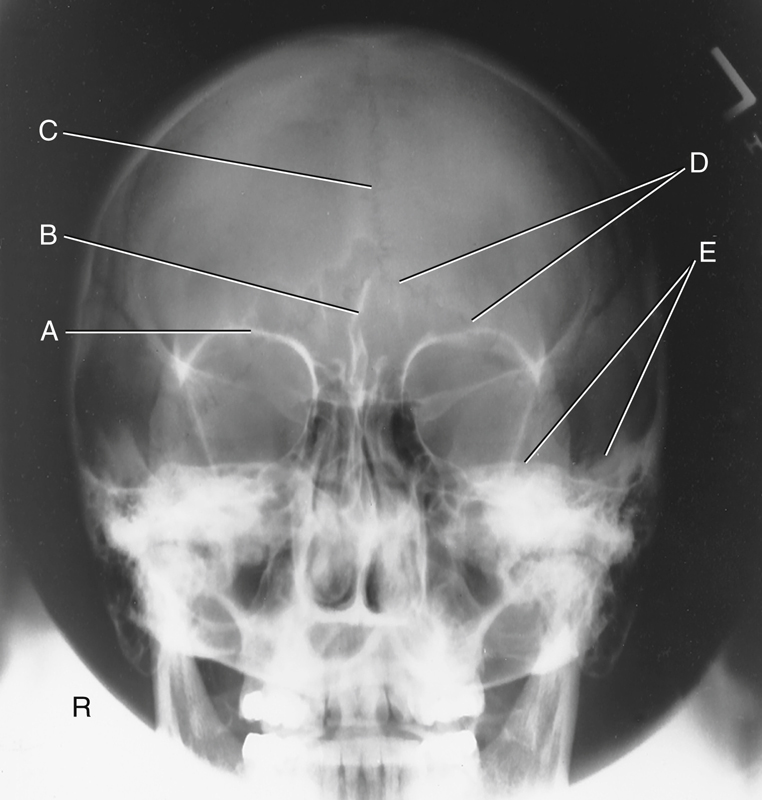
Cranial Bones—PA Axial Caldwell Projection, 15° caudad (Fig. 11.21)
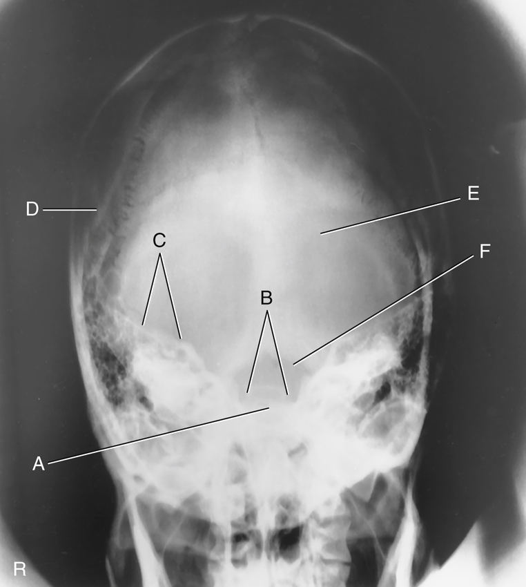
Cranial Bones—AP Axial Projection (Fig. 11.22)
Cranial Bones—Lateral Projection (Fig. 11.23)
- A. EAM
- B. Mastoid portion of temporal bone
- C. Occipital bone
- D. Lambdoidal suture
- E. Clivus
- F. Dorsum sellae
- G. Posterior clinoid processes
- H. Anterior clinoid processes
- I. Vertex of cranium
- J. Coronal suture
- K. Frontal bone
- L. Orbital plates
- M. Cribriform plate
- N. Sella turcica
- O. Body of sphenoid (sphenoid sinus)
- P. Petrous portion of temporal bone

Anatomy of Organs of Hearing and Equilibrium
Because of the density (brightness) and relative location of the temporal bones, the mastoids and petrous portions are difficult to visualize with conventional radiography. CT and MRI have largely replaced conventional radiography for imaging of these regions. However, a knowledge of temporal bone anatomy is critical whether performing conventional radiography, CT, or MRI.
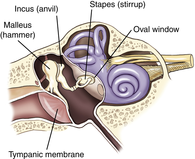
The organs of hearing and equilibrium are the main structures found within the petrous portion of the temporal bones. The three divisions of the ear—external, middle, and internal portions—are illustrated in Fig. 11.24.
External Ear
The external ear begins with the auricle or pinna on each side of the head. The tragus is part of this external structure. It is the small liplike structure located anterior to the EAM that acts as a partial shield to the ear opening.
The EAM is the opening or canal of the external ear. The external acoustic canal or meatus is approximately 1 inch (2.5 cm) long; half is bony in structure, and half is cartilaginous (Fig. 11.25).
The mastoid process and mastoid tip of the temporal bone are posterior and inferior to the EAM, whereas the styloid process is inferior and slightly anterior. The meatus narrows as it meets the tympanic membrane or eardrum. The eardrum is situated at an oblique angle, forming a depression, or well, at the lower medial end of the meatus.
Middle Ear
The middle ear is an irregularly shaped, air-containing cavity located between the external and internal ear portions. The three main parts of the middle ear are the tympanic membrane, the three small bones called auditory ossicles, and the tympanic cavity (Fig. 11.26). The tympanic membrane is considered part of the middle ear even though it serves as a partition between the external and middle ears.
The tympanic cavity is divided further into two parts. The larger cavity opposite the eardrum is called the tympanic cavity proper. The area above the level of the EAM and the eardrum is called the attic, or epitympanic recess. The drum crest, or spur, is a structure that is important radiographically. The tympanic membrane is attached to this sharp, bony projection. The drum crest or spur separates the EAM from the epitympanic recess.
The tympanic cavity communicates anteriorly with the nasopharynx by way of the eustachian tube, or auditory tube.


Computed Tomography of the Temporal Bone
Fig. 11.27 demonstrates select organs of hearing and equilibrium of the middle and inner ear as seen on this CT of the temporal bone.
Eustachian Tube
The eustachian tube is the passageway between the middle ear and the nasopharynx. This tube is approximately 1½ inches (4 cm) long and serves to equalize the pressure within the middle ear to the outside atmospheric air pressure through the nasopharynx (Fig. 11.28). The sensation of one’s ears popping is caused by pressure being adjusted internally in the middle ear to prevent damage to the eardrum.
A problem associated with this direct communication between the middle ear and the nasopharynx is that disease organisms have a direct passageway from the throat to the middle ear. Therefore, ear infections often accompany sore throats, especially in children whose immune system is still developing.
Internal Acoustic Meatus
Fig. 11.29 illustrates the ear structures as they would appear in a modified posteroanterior (PA) projection. A 5° to 10° central ray (CR) caudad angle to the orbitomeatal line projects the petrous ridges to the midorbital level, as is shown in this drawing. This results in a special transorbital view, which may be taken to demonstrate the internal acoustic meatus. The opening to the internal acoustic meatus is an oblique aperture that is smaller in diameter than the opening to the EAM and is very difficult to demonstrate clearly on any conventional radiographic projection. It is best demonstrated with CT (for bony erosion) and MRI (for demonstration of acoustic neuromas).
In the drawing of a PA axial projection (see Fig. 11.29), the internal acoustic meatus is projected into the orbital shadow slightly below the petrous ridge, allowing it to be visualized on radiographs taken in this position. The lateral portions of the petrous ridges are at approximately the level of the TEA.
Mastoids
A second direct communication into the middle ear occurs posteriorly to the mastoid air cells. The schematic drawing in Fig. 11.30 is a sagittal section that shows the relationships of the mastoid air cells to the attic, or epitympanic recess, and the tympanic cavity proper. The aditus is the opening between the epitympanic recess and the mastoid portion of the temporal bone.
The aditus connects directly to a large chamber within the mastoid portion termed the antrum. The antrum connects to the various mastoid air cells. This communication allows infection in the middle ear, which may have originated in the throat, to pass into the mastoid area. Infection within the mastoid area is separated from brain tissue only by thin bone. Before effective antibiotics were commonly used, this was often a pathway for encephalitis, a serious infection of the brain. The thin plate of bone that forms the roof of the antrum, aditus, and attic area of the tympanic cavity is called the tegmen tympani.


Auditory Ossicles
The auditory ossicles are three small bones that are prominent structures within the middle ear. Figs. 11.31 and 11.32 show that these three small bones are articulated to permit vibratory motion. The three auditory ossicles are located partly in the attic, or epitympanic recess, and partly in the tympanic cavity proper. These delicate bones bridge the middle ear cavity to transmit sound vibrations from the tympanic membrane to the oval window of the internal ear.
Vibrations are first picked up by the malleus, meaning “hammer,” which is attached directly to the inside surface of the tympanic membrane. The head of the malleus articulates with the central ossicle, the incus. The incus receives its name from a supposed resemblance to an anvil, but it actually looks more like a premolar tooth with a body and two roots. The incus connects to the stirrup-shaped stapes, which is the smallest of the three auditory ossicles. The footplate of the stapes is attached to another membrane called the oval window, which leads into the inner ear.
Auditory Ossicles—Frontal and Lateral View
Fig. 11.32 illustrates the relationship of the auditory ossicles to one another in a close-up frontal view and a lateral view. As can be seen from the front, the most lateral of the three bones is the malleus, whereas the most medial of the three bones is the stapes. The lateral view drawing demonstrates how the ossicles would appear if one looked through the EAM to see the bony ossicles of the middle ear. The malleus, with its attachment to the eardrum, is located slightly anterior to the other two bones.
The resemblance of the incus to a premolar tooth with a body and two roots is well visualized in the lateral drawing. The longer root of the incus connects to the stapes, which connects to the oval window of the cochlea, resulting in the sense of hearing.
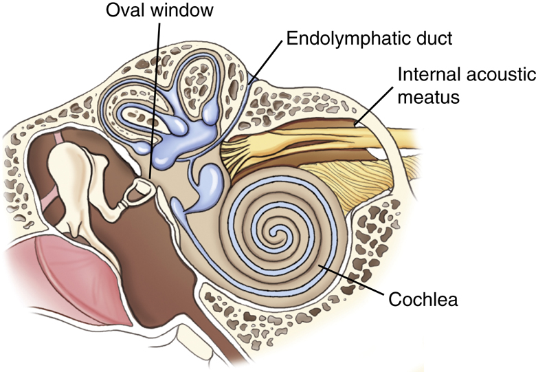
Internal Ear
The complex internal ear contains the essential sensory apparatus of both hearing and equilibrium. Lying within the densest portion of the petrous pyramid, it can be divided into two main parts—the osseous, or bony, labyrinth, which is important radiographically, and the membranous labyrinth. The osseous labyrinth is a bony chamber that houses the membranous labyrinth, a series of intercommunicating ducts and sacs. One such duct is the endolymphatic duct, a blind pouch or closed duct contained in a small, canal-like, bony structure. The canal of the endolymphatic duct arises from the medial wall of the vestibule and extends to the posterior wall of the petrous pyramid, located both posterior and lateral to the internal acoustic meatus.
Osseous (Bony) Labyrinth
The osseous, or bony, labyrinth is divided into three distinctly shaped parts: the cochlea (meaning “snail shell”), the vestibule, and the semicircular canals. The osseous labyrinth completely surrounds and encloses the ducts and sacs of the membranous labyrinth. As is illustrated on the frontal cutaway view in Fig. 11.33, the snail-shaped, bony cochlea houses a long, coiled, tubelike duct of the membranous labyrinth.
The cochlea is the most anterior of the three parts of the osseous labyrinth. This is best shown on the lateral view of the osseous labyrinth in Fig. 11.34. The round window, sometimes called the cochlear window, is shown to be at the base of the cochlea.
The vestibule, the central portion of the bony labyrinth, contains the oval window, sometimes called the vestibular window.
Semicircular Canals
The three semicircular canals are located posterior to the other inner ear structures and are named according to their position: superior, posterior, and lateral semicircular canals. Each is located at a right angle to the other two, allowing a sense of equilibrium in addition to a sense of direction. The semicircular canals relate to the sense of direction or equilibrium, and the cochlea relates to the sense of hearing because of its connection to the stapes through the oval window.

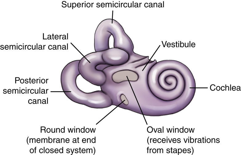
“Windows” of the Internal Ear
The two openings into the internal ear are covered by membranes (see Fig. 11.34). The oval, or vestibular, window receives vibrations from the external ear through the distal aspect of the stapes of the middle ear and transmits these vibrations into the vestibule of the internal ear. The vestibule is the structure that houses the semicircular canals. The round, or cochlear, window is located at the base of the first coil of the cochlea. The round window is a membrane that allows movement of fluid within the closed duct system of the membranous labyrinth. As the oval window moves slightly inward with a vibration, the round window moves outward because this is a closed system and fluid does not compress. Vibrations and associated slight fluid movements within the cochlea produce impulses that are transmitted to the auditory nerve within the internal acoustic meatus, creating the sense of hearing.
Anatomy Review With Radiographs
Specific anatomy of the temporal bone is difficult to recognize on conventional radiographs. Conventional positioning for mastoids is rarely performed today, but these two projections are provided to review the anatomy of the inner ear and mastoids.
Axiolateral Projection (Fig. 11.35)
Posterior Profile Position (Fig. 11.36)


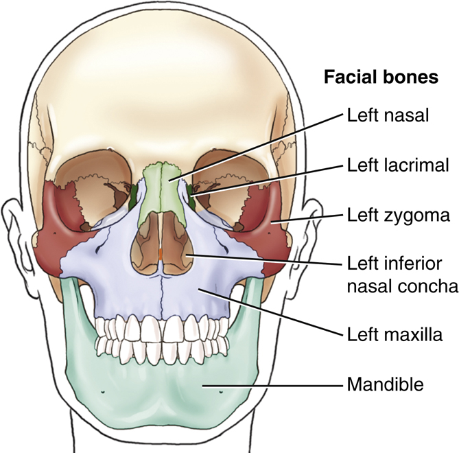
Facial Bones
Each of the facial bones can be identified on frontal and lateral drawings (Figs. 11.37 and 11.38) except for the two palatine bones and the vomer, both of which are located internally and are not visible on a dry skeleton from the exterior. These bones are identified on sectional drawings later in this chapter.
The 14 facial bones contribute to the shape and form of a person’s face. In addition, the cavities of the orbits, nose, and mouth are largely constructed from the bones of the face. Of the 14 bones that make up the facial skeleton, only 2 bones are unpaired, the vomer and mandible. The remaining 12 consist of six pairs of bones, with similar bones on each side of the face.
| 2 | Maxillae (mak-sil′-e) (upper jaw), or maxillary bones |
|---|---|
| 2 | Zygomatic (zi″-go-mat′-ik) bones |
| 2 | Lacrimal (lak′-ri-mal) bones |
| 2 | Nasal bones |
| 2 | Inferior nasal conchae (kong′-ke) |
| 2 | Palatine (pal′-ah-tin) bones |
| 1 | Vomer (vo′-mer) |
| 1 | Mandible (lower jaw) |
| 14 | Total |
Each of the facial bones is studied individually or in pairs. After the description of each in the figures is a listing of the specific adjoining bones with which they articulate. Knowledge of these anatomic relationships aids in understanding the structure of the bony skeleton of the head.
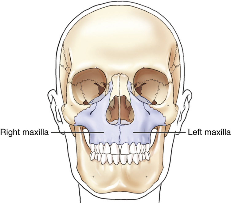
Right and Left Maxillary Bones
The two maxillae, or maxillary bones, are the largest immovable bones of the face (Fig. 11.39). The only facial bone larger than the maxilla is the movable lower jaw, or mandible. All the other bones of the upper facial area are closely associated with the two maxillae; they are structurally the most important bones of the upper face. The right and left maxillary bones are solidly united at the midline below the nasal septum. Each maxilla assists in the formation of three cavities of the face: (1) the mouth, (2) the nasal cavity, and (3) one orbit.

Lateral View of Left Maxilla
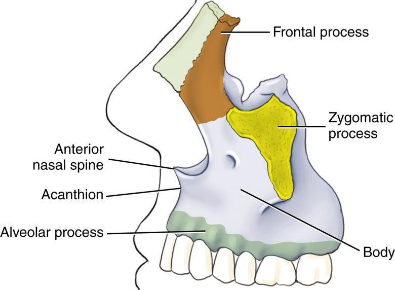
Each maxilla consists of a centrally located body and four processes that project from that body. Three processes are more obvious and are visible on lateral and frontal drawings (Figs. 11.40 and 11.41). The fourth process, described later, is the palatine process, which is part of the hard palate.
The body of each maxilla is the centrally located portion that lies lateral to the nose. One of the three processes is the frontal process, which projects upward along the lateral border of the nose toward the frontal bone. The zygomatic process projects laterally to unite with the zygoma. The third process, the alveolar process, is the inferior aspect of the body of each maxilla. Eight upper teeth occur along the inferior margin of each alveolar process.
The two maxillae are solidly united in the midline anteriorly. At the upper part of this union is the anterior nasal spine. A blow to the nose sometimes results in separation of the nasal spine from the maxillae.
A point at the superior aspect of the anterior nasal spine is the acanthion, which is described later in this chapter as a surface landmark at the midline point where the nose and the upper lip meet.
Frontal View
The relationship of the two maxillary bones to the remainder of the bones of the skull is well demonstrated in the frontal view (see Fig. 11.41). Note again three processes, as seen in the frontal view of the skull. Extending upward toward the frontal bone is the frontal process. Extending laterally toward the zygoma is the zygomatic process, and supporting the upper teeth is the alveolar process.
The body of each maxillary bone contains a large, air-filled cavity known as a maxillary sinus. Several of these air-filled cavities are found in certain bones of the skull. These sinuses communicate with the nasal cavity and are collectively termed paranasal sinuses; they are described further later on in this chapter.
Hard Palate (Inferior Surface)
The fourth process of each maxillary bone is the palatine process, which can be demonstrated only on an inferior view of the two maxillae (Fig. 11.42). The two palatine processes form the anterior portion of the roof of the mouth, called the hard or bony palate. The two palatine processes are solidly united at the midline to form a synarthrodial (immovable) joint. A common congenital defect called a cleft palate is an opening between the palatine processes that is caused by incomplete joining of the two bones.
The horizontal portion of two other facial bones, the palatine bones, forms the posterior part of the hard palate. Only the horizontal portions of the L-shaped palatine bones are visible on this view. The vertical portions are demonstrated later on a cutaway drawing (see Fig. 11.47).
Note the differences between the palatine process of the maxillary bone and the separate palatine facial bones.
The two small inferior portions of the sphenoid bone of the cranium also are shown on this inferior view of the hard palate. These two processes, the pterygoid hamuli, are similar to the feet of the outstretched legs of a bat, as described in an earlier drawing in the chapter (also see Fig. 11.15, p. 384).
Articulations
Each maxilla articulates with two cranial bones (frontal and ethmoid) and with seven facial bones (zygoma, lacrimal, nasal, palatine, inferior nasal concha, vomer, and adjacent maxilla).


Right and Left Zygomatic Bones
One zygoma is located lateral to the zygomatic process of each maxilla. These bones (sometimes termed malar bones) form the prominence of the cheeks and make up the lower outer portion of the orbits.
Projecting posteriorly from the zygoma is a slender process that connects with the zygomatic process of the temporal bone to form the zygomatic arch. The zygomatic arch is a delicate structure that sometimes is fractured or “caved in” by a blow to the cheek. The anterior portion of the arch is formed by the zygoma, and the posterior portion is formed by the zygomatic process of the temporal bone. The zygomatic prominence is a positioning landmark, and the term refers to this prominent portion of the zygoma (Fig. 11.43).
Articulations
Each zygoma articulates with three cranial bones (frontal, sphenoid, and temporal) and with one facial bone (maxilla).
Right and Left Nasal and Lacrimal Bones
The lacrimal and nasal bones are the thinnest and most fragile bones in the entire body.
Lacrimal Bones
The two small and delicate lacrimal bones (about the size and shape of a fingernail) lie anteriorly on the medial side of each orbit just posterior to the frontal process of the maxilla (Fig. 11.44). Lacrimal, derived from a word meaning “tear,” is an appropriate term because the lacrimal bones are closely associated with the tear ducts.
Nasal Bones
The two fused nasal bones form the bridge of the nose and are variable in size. Some people have very prominent nasal bones, whereas nasal bones are quite small in other people. Much of the nose is made up of cartilage, and only the two nasal bones form the bridge of the nose. The nasal bones lie anterior and superomedial to the frontal process of the maxillae and inferior to the frontal bone. The point of junction of the two nasal bones with the frontal bone is a surface landmark called the nasion (Fig. 11.45).
Articulations
Lacrimal
Each lacrimal bone articulates with two cranial bones (frontal and ethmoid) and with two facial bones (maxilla and inferior nasal concha).
Nasal
Each nasal bone articulates with two cranial bones (frontal and ethmoid) and with two facial bones (maxilla and adjacent nasal bone) (see Fig. 11.45).


Right and Left Inferior Nasal Conchae
Within the nasal cavity are two platelike, curved (or scroll-shaped) facial bones called the inferior nasal conchae (turbinates). These two bones project from the lateral walls of the nasal cavity on each side and extend medially (Fig. 11.46).
There are three pairs of nasal conchae. The superior and middle pairs are parts of the ethmoid bone, and the inferior pair consists of separate facial bones.
The effect of the three pairs of nasal conchae is to divide the nasal cavities into various compartments. These irregular compartments tend to break up or mix the flow of air coming into the nasal cavities before it reaches the lungs. In this way, incoming air is warmed and cleaned as it comes in contact with the mucous membrane that covers the conchae.
Sectional Drawing
Inferior Nasal Conchae
The relationship between the various nasal conchae and the lateral wall of one nasal cavity is illustrated in this sectional drawing (Fig. 11.47). The midline structures that make up the nasal septum have been removed so that the lateral portion of the right nasal cavity can be seen. The superior and middle conchae are part of the ethmoid bone, and the inferior nasal conchae are separate facial bones. The cribriform plate and the crista galli of the ethmoid bone help to separate the cranium from the facial bone mass. The palatine process of the maxilla is shown again.
Right and Left Palatine Bones
The two palatine bones are difficult to visualize in the study of a dry skeleton because they are located internally and are not visible from the outside. Each palatine bone is roughly L-shaped (see Fig. 11.47). The vertical portion of the “L” extends upward between one maxilla and one pterygoid plate of the sphenoid bone. The horizontal portion of each “L” helps to make up the posterior portion of the hard palate, as shown in an earlier drawing (see Fig. 11.42). Additionally, the most superior small tip of the palatine can be seen in the posterior aspect of the orbit (see Fig. 11.71, p. 401).
Articulations
Inferior Nasal Conchae
Each inferior nasal concha articulates with one cranial bone (ethmoid) and with three facial bones (maxilla, lacrimal, and palatine).
Palatine
Each palatine articulates with two cranial bones (sphenoid and ethmoid) and four facial bones (maxilla, inferior nasal conchae, vomer, and adjacent palatine).
Nasal Septum
The midline structures of the nasal cavity, including the bony nasal septum, are shown on this sagittal view drawing (Fig. 11.48). Two bones—the ethmoid and the vomer—form the bony nasal septum. Specifically, the septum is formed superiorly by the perpendicular plate of the ethmoid bone and inferiorly by the single vomer bone, which can be demonstrated radiographically. Anteriorly, the nasal septum is cartilaginous and is termed the septal cartilage.
Vomer
The single vomer (meaning “plowshare”) bone is a thin, triangular bone that forms the inferoposterior part of the nasal septum. The surfaces of the vomer are marked by small, furrow-like depressions for blood vessels, a source of nosebleed with trauma to the nasal area. A deviated nasal septum describes the clinical condition wherein the nasal septum is deflected or displaced laterally from the midline of the nose. This deviation usually occurs at the site of junction between the septal cartilage and the vomer. A severe deviation can entirely block the nasal passageway, making breathing through the nose impossible.
Articulations


Mandible
The last and largest facial bone is the lower jaw, or mandible. It is the only movable bone in the adult skull. This large facial bone, which is a single bone in the adult, originates from two separate bones. The two bones in the infant join to become one at approximately 1 year of age.
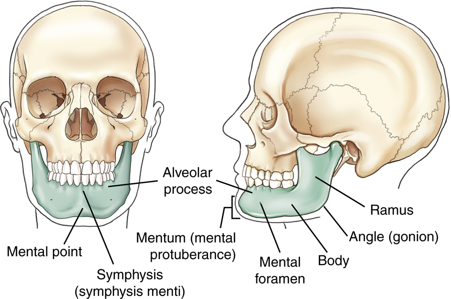
Lateral View
The angle (gonion) of the mandible divides each half of the mandible into two main parts. That area anterior to the angle is termed the body of the mandible, whereas the area superior to each angle is termed the ramus. Because the mandible is a single bone, the body extends from the left angle around to the right angle (Fig. 11.49).
The lower teeth are rooted in the mandible. An alveolar process, or ridge, extends along the entire superior portion of the body of the mandible.
Frontal View
The anterior aspect of the adult mandible is best seen on a frontal view. The single body forms from each lateral half and unites at the anterior midline. This union is called the symphysis of the mandible, or the symphysis menti. The flat triangular area below the symphysis, marked by two knoblike protuberances that project forward, is called the mental protuberance. The center of the mental protuberance is described as the mental point. Mentum and mental are Latin words that refer to the general area known as the chin. The mental point is a specific point on the chin, whereas the mentum is the entire area.
Located on each half of the body of the mandible is a mental foramen. The mental foramina serve as passageways for the mental artery and vein and mental nerve (branch of inferior alveolar nerve) that innervates the lower lip and chin.
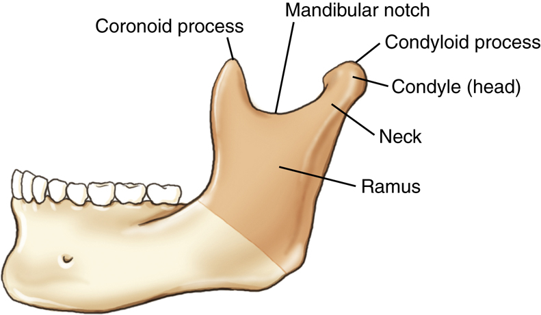
Ramus
The upper portion of each ramus terminates in a U-shaped notch termed the mandibular notch. At each end of the mandibular notch is a process. The process at the anterior end of the mandibular notch is termed the coronoid process (Fig. 11.50). This process does not articulate with another bone and cannot be palpated easily because it lies just inferior to the zygomatic arch and serves as a site for muscle attachment.
The coronoid process of the mandible must not be confused with the coronoid process of the proximal ulna of the forearm or the coracoid process of the scapula.
The posterior process of the upper ramus is termed the condyloid process and consists of two parts. The rounded end of the condyloid process is the condyle or head, whereas the constricted area directly below the condyle is the neck. The condyle of the condyloid process fits into the TM fossa of the temporal bone to form the TMJ.
Submentovertical Projection
The horseshoe shape of the mandible is well visualized on a submentovertical (SMV) projection (Fig. 11.51). The mandible is a thin structure, which explains why it is susceptible to fracture. The area of the mentum is well demonstrated, as are the body, ramus, and gonion of the mandible. The relative position of the upper ramus and its associated coronoid process and condyle are also demonstrated with this projection. The condyle projects medial and the coronoid process slightly lateral on this view.

Temporomandibular Joint
The TMJ, the only movable joint in the skull, is shown on this lateral drawing (Fig. 11.52) and on the lateral view photograph of the skull (Fig. 11.53). The relationship of the mandible to the temporal bone of the cranium is well demonstrated. The TMJ is located just anterior and slightly superior to the EAM.
Joint Classifications (Mandible and Skull)
Synovial Joints (Diarthrodial)
The complex TMJ is classified as a synovial type of joint divided into upper and lower synovial cavities by a single articular fibrous disk (Table 11.1). A series of strong ligaments join the condylar neck, ramus, and gonion of the mandible to the lower borders of the zygomatic process of the temporal bone.
This complete two-part synovial joint, along with its fibrous articular disk, allows for not only a hinge-type motion but also a gliding movement. The action of this type of joint is very complex. Two movements are predominant. When the mouth opens, the condyle and the fibrocartilage move forward, and at the same time, the condyle revolves around the fibrocartilage. The TMJ is classified as a bicondylar joint similar to the knee.
3
Fibrous Joints (Synarthrodial)
Two types of fibrous joints involve the skull, both of which are synarthrodial, or immovable. First are the sutures between cranial bones, as described earlier. Second is a unique type of fibrous joint involving the teeth with the mandible and maxillae. This is a gomphosis (gom-fo′-sis) subclass type of fibrous joint that is found between the roots of the teeth and the alveolar processes of both the maxillae and the mandible.
TMJ Motion
The drawings and radiographs illustrate the TMJ in both open-mouth and closed-mouth positions (Fig. 11.54). When the mouth is opened widely, the condyle moves forward to the front edge of the fossa. If the condyle slips too far anteriorly, the joint may dislocate. If the TMJ dislocates, either by force or by jaw motion, it may be difficult or impossible to close the mouth, which returns the condyle to its normal position.
Radiographs (Open and Closed Mouth)
Two axiolateral projections (Schuller method) of the TMJ are shown in closed-mouth and open-mouth positions (Figs. 11.55 and 11.56). The range of anterior movement of the condyle in relationship to the TM fossa is clearly demonstrated.


Paranasal Sinuses
The large, air-filled cavities of the paranasal sinuses are sometimes called the accessory nasal sinuses because they are lined with mucous membrane, which is continuous with the nasal cavity. These sinuses are divided into four groups, according to the bones that contain them:
| Maxillary (2) | Maxillary (facial) bones |
|---|---|
| Frontal (usually 2) | Frontal (cranial) bones |
| Ethmoid (many) | Ethmoid (cranial) bones |
| Sphenoid (1 or 2) | Sphenoid (cranial) bone |
Only the maxillary sinuses are part of the facial bone structure. The frontal, ethmoid, and sphenoid sinuses are contained within their respective cranial bones (Fig. 11.57
).
Purpose
The purpose of the paranasal sinuses is subject to speculation. Various sources suggest they assist in vocal resonance, lighten the weight of the skull, and produce mucus to moisten the nasal passageways and air entering the nasal airway.
The paranasal sinuses begin to develop in the fetus, but only the maxillary sinuses exhibit a definite cavity at birth. The frontal and sphenoid sinuses begin to be visible on radiographs at age 6 or 7. The ethmoid sinuses develop last. All the paranasal sinuses generally are fully developed by the late teenage years.
Each of these groups of sinuses is studied, beginning with the largest, the maxillary sinuses.
Maxillary Sinuses
The large maxillary sinuses are paired structures, one of which is located within the body of each maxillary bone. An older term for maxillary sinus is antrum, an abbreviation for antrum of Highmore.
Each maxillary sinus is shaped like a pyramid on a frontal view. Laterally, the maxillary sinuses appear more cubic. The average total vertical dimension is 1 to 1½ inches (2.5 to 4 cm), and the other dimensions are approximately 1 inch (2.5 cm).
The bony walls of the maxillary sinuses are thin. The floor of each maxillary sinus is slightly below the level of the floor of each nasal fossa. The two maxillary sinuses vary in size from one person to another and sometimes from one side to the other. Projecting into the floor of each maxillary sinus are several conic elevations related to roots of the first and second upper molar teeth (Fig. 11.58). Occasionally, one or more of these roots can allow infection that originates in the teeth, particularly in the molars and premolars, to travel upward into the maxillary sinus.
All the paranasal sinus cavities communicate with one another and with the nasal cavity, which is divided into two equal chambers, or fossae. In the case of the maxillary sinuses, this site of communication is the opening into the middle nasal meatus passageway located at the superior medial aspect of the sinus cavity itself, as demonstrated in Fig. 11.59. (The osteomeatal complex is illustrated in greater detail later in Figs. 11.63 and 11.64.) When a person is erect, any mucus or fluid trapped within the sinus tends to remain there and layer out, forming an air-fluid level. Therefore, radiographic positioning of the paranasal sinuses should be accomplished with the patient in the erect position, if possible, to delineate any possible air-fluid levels.


Frontal Sinuses
The frontal sinuses are located between the inner and outer tables of the skull, posterior to the glabella; they rarely become aerated before age 6. Whereas the maxillary sinuses are always paired and are usually fairly symmetric in size and shape, the frontal sinuses are rarely symmetric (Fig. 11.60). The frontal sinuses usually are separated by a septum, which deviates from one side to the other or may be absent entirely, resulting in a single cavity. However, two cavities generally exist, which vary in terms of size and shape. They generally are larger in men than in women. They may be singular on the right or the left side, they may be paired as shown, or they may be absent.
Ethmoid Sinuses
The ethmoid sinuses are contained within the lateral masses or labyrinths of the ethmoid bone. These air cells are grouped into anterior, middle, and posterior collections, but they all intercommunicate (Fig. 11.61).
When viewed from the side, the anterior ethmoid sinuses appear to fill the orbits. This occurs because portions of the ethmoid sinuses are contained in the lateral masses of the ethmoid bone, which helps to form the medial wall of each orbit.
Sphenoid Sinuses
The sphenoid sinuses lie in the body of the sphenoid bone directly below the sella turcica (Fig. 11.62). The body of the sphenoid that contains these sinuses is cubic and frequently is divided by a thin septum to form two cavities. This septum may be incomplete or absent entirely, resulting in only one cavity.
Because the sphenoid sinuses are so close to the base or floor of the cranium, sometimes pathologic processes make their presence known by their effect on these sinuses. An example is the demonstration of an air-fluid level within the sphenoid sinuses after skull trauma. This air-fluid level may provide evidence that the patient has a basal skull fracture and that either blood or cerebrospinal fluid is leaking through the fracture into the sphenoid sinuses, a condition referred to as sphenoid effusion.
Osteomeatal Complex
The drainage pathways of the frontal, maxillary, and ethmoid sinuses make up the osteomeatal complex, which can become obstructed, leading to infection of these sinuses, a condition termed sinusitis. The osteomeatal complex, sometimes called the osteomeatal unit (OMU), can be imaged with CT to evaluate for obstructions.
Figs. 11.63 and 11.64 illustrate two key passageways (infundibulum and middle nasal meatus) and their associated structures identified on coronal CT. The large maxillary sinus drains through the infundibulum passageway down through the middle nasal meatus into the inferior nasal meatus. The uncinate process of the ethmoid bone makes up the medial wall of the infundibulum passageway. The ethmoid bulla receives drainage from the frontal and ethmoid sinus cells, which drains down through the middle nasal meatus into the inferior nasal meatus, where it exits the body through the exterior nasal orifice.


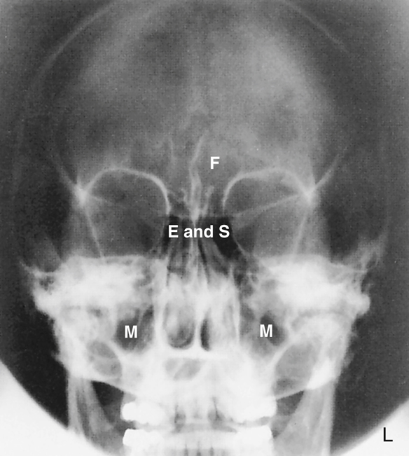
Radiographs—Paranasal Sinuses
Drawings of the sinuses on preceding pages revealed definite sizes and shapes of the sinuses with clear-cut borders. On actual radiographs, these borders are not nearly as defined because various sinuses overlap and superimpose each other, as can be seen on these radiographs of four common sinus projections. The labeled radiographs clearly demonstrate the relative locations and relationships of each of these sinuses. (Note the following abbreviations: F—frontal sinuses; E—ethmoid sinuses; M—maxillary sinuses; and S—sphenoid sinuses.)
Lateral Position
The frontal sinuses are clearly visualized between the inner and outer tables of the skull (Fig. 11.65).
The sphenoid sinuses appear to be continuous with the ethmoid sinuses anteriorly.
The large maxillary sinuses are clearly visualized. The roots of the molars and premolars of the upper teeth appear to extend up through the floor of the maxillary sinuses.
PA (Caldwell) Projection
The frontal, ethmoid, and maxillary sinuses are clearly illustrated on this PA axial projection radiograph (Fig. 11.66). The sphenoid sinuses are not demonstrated specifically because they are located directly posterior to the ethmoid sinuses. This relationship is demonstrated on the lateral view (see Fig. 11.65) and the SMV projection (see Fig. 11.68).
Parietoacanthial Transoral Projection (Open-Mouth Waters)
All four groups of sinuses are clearly demonstrated on this projection taken with the mouth open and the head tipped back to separate and project the sphenoid sinuses inferior to the ethmoid sinuses (Fig. 11.67). The open mouth also removes the upper teeth from direct superimposition of the sphenoid sinuses. The pyramid-shaped maxillary sinuses are clearly seen.
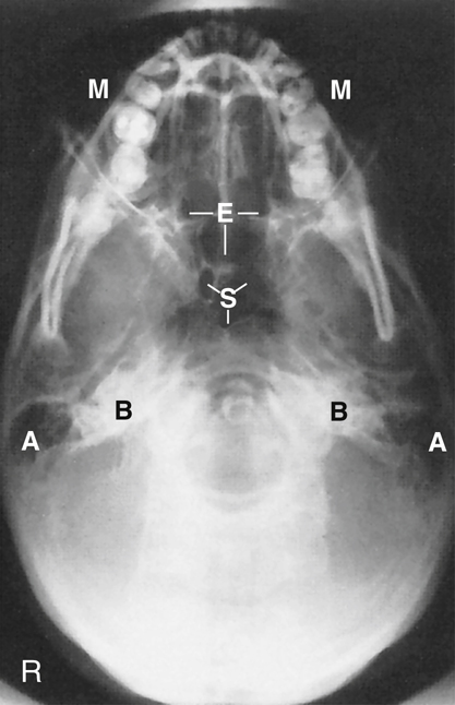
SMV Projection
The SMV projection is obtained with the head tipped back so that the top of the head (vertex) is touching the table/upright imaging device surface and the CR is directed inferior to the chin (mentum) (Fig. 11.68).
The centrally located sphenoid sinuses are anterior to the large opening, the foramen magnum. The multiple clusters of ethmoid air cells extend to each side of the nasal septum. The mandible and teeth superimpose the maxillary sinuses. Portions of the maxillary sinuses are visualized laterally.
Fig. 11.68 demonstrates these air-filled mastoids (labeled A) and the dense petrous portions of the temporal bones (labeled B).


Orbits
The complex anatomy of the 14 facial bones helps to form several facial cavities. These cavities, which are formed in total or in part by the facial bones, include the mouth (oral cavity), the nasal cavities, and the orbits. The mouth and nasal cavities are primarily passageways and are rarely imaged. However, the orbits that contain the vital organs of sight and associated nerves and blood vessels are imaged more frequently. The structure and shape of the orbits are illustrated in this simplified drawing (Fig. 11.69). Each orbit is a cone-shaped, bony-walled structure, as is shown in the drawing.
The rim of the orbit, which corresponds to the outer circular portion of the cone, is called the base. However, the base of the orbit is not a true circle and may even look like a figure with four definite sides. The posterior portion of the cone, the apex, corresponds to the optic foramen, through which the optic nerve passes.
The long axis of the orbits projects both upward and toward the midline. With the head placed in an upright frontal or lateral position with the orbitomeatal line adjusted parallel to the floor, each orbit would project superiorly at an angle of 30° and toward the MSP at an angle of 37°. These two angles are important for radiographic positioning of the optic foramina. Each optic foramen is located at the apex of its respective orbit. To radiograph either optic foramen, it is necessary both to extend the patient’s chin by 30° and to rotate the head 37°. The CR projects through the base of the orbit along the long axis of the cone-shaped orbit.
Bony Composition of Orbits
Each orbit is composed of parts of seven bones. The circumference or circular base of each orbit is composed of parts of three bones—the frontal bone (orbital plate) from the cranium and the maxilla and the zygoma from the facial bones (Fig. 11.70). A roof, a floor, and two walls, parts of which also are formed by these three bones, are found inside each orbital cavity. The orbital plate of the frontal bone forms most of the roof of the orbit. The zygoma forms much of the lateral wall and some of the floor of the orbit, whereas a portion of the maxilla helps to form the floor.
The slightly oblique frontal view in Fig. 11.71 demonstrates all seven bones that form each orbit. The frontal bone, zygoma, and maxilla, which form the base of the orbit, are shown again. A portion of the medial wall of the orbit is formed by the thin lacrimal bone. The sphenoid and ethmoid bones make up most of the posterior orbit, whereas only a small bit of the palatine bone contributes to the innermost posterior portion of the floor of each orbit.
The seven bones that make up each orbit include three cranial bones and four facial bones, as shown in Box 11.1.


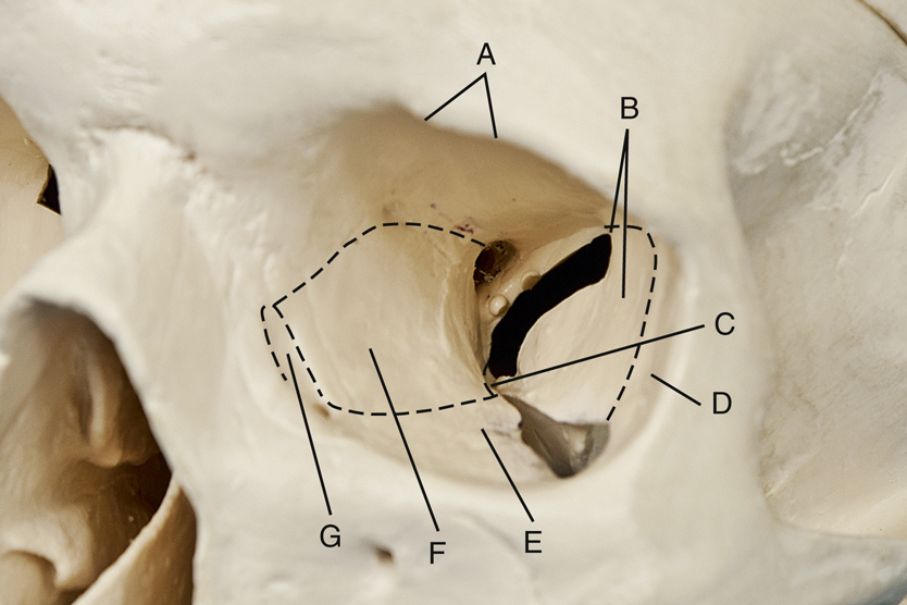
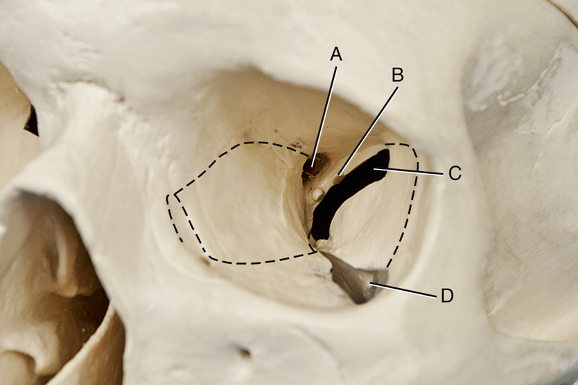
Openings in Posterior Orbit
Each orbit also contains three holes or openings in the posterior portion, as shown in Fig. 11.72. These openings provide for passage of specific cranial nerves (CN). (The 12 pairs of cranial nerves are listed and described in the anatomy section of Chapter 18.)
The optic foramen is a small hole in the sphenoid bone that is located posteriorly at the apex of the cone-shaped orbit. The optic foramen allows for passage of the optic nerve (CN II), which is a continuation of the retina.
The superior orbital fissure is a cleft or opening between the greater and lesser wings of the sphenoid bone, located lateral to the optic foramen. It allows transmission of four primary cranial nerves (CN III to CN VI), which control movement of the eye and eyelid.
A third opening is the inferior orbital fissure, which is located between the maxilla, zygomatic bone, and greater wing of the sphenoid. It allows for transmission of the maxillary branch of CN V, which permits entry of sensory innervation for the cheek, nose, upper lip, and teeth.
The small root of bone that separates the superior orbital fissure from the optic canal is known as the sphenoid strut. The optic canal is a small canal into which the optic foramen opens. Any abnormal enlargement of the optic nerve could cause erosion of the sphenoid strut, which is actually a portion of the lateral wall of the optic canal.
Anatomy Review
Review exercises for anatomy of the cranial and facial bones follow. Anatomy can be demonstrated on a dry skull or on radiographs. Some anatomic parts identified on the dry skull are not visualized on these radiographs. The parts that are identifiable are labeled as such. A good learning or review exercise is to study both the skull illustrations and the radiographs carefully and identify each part before looking at the answers listed next.
Seven Bones of Left Orbit (Fig. 11.73)
Openings and Structures of Left Orbit (Fig. 11.74)
Parieto-Orbital Oblique (Rhese method) Projection of Orbits (Fig. 11.75)


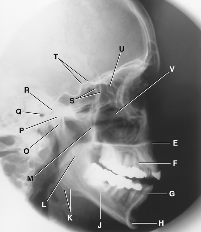
Facial Bones—Lateral (Figs. 11.76 and 11.77)
- A. Zygomatic arch
- B. Right zygomatic bone
- C. Right nasal bone
- D. Frontal process of right maxilla
- E. Anterior nasal spine
- F. Alveolar process of maxilla
- G. Alveolar process of mandible
- H. Mentum or mental protuberance
- I. Mental foramen
- J. Body of mandible
- K. Angle (gonion)
- L. Ramus of mandible
- M. Coronoid process
- N. Mandibular notch
- O. Neck of mandibular condyle
- P. Condyle or head of mandible
- Q. EAM
- R. TM fossa of temporal bone
- S. Greater wings of sphenoid
- T. Lesser wings of sphenoid with anterior clinoid processes
- U. Ethmoid sinuses between orbits
- V. Body of maxilla containing maxillary sinuses
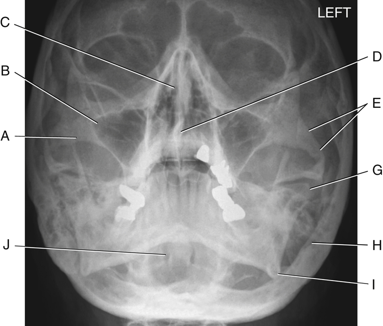
Facial Bones—Parietoacanthial (Waters)
The photograph (Fig. 11.78) and the radiograph (Fig. 11.79) represent the skull in a parietoacanthial projection (Waters method), with the head tilted back. This is one of the more common projections used to visualize the facial bones, as follows:
- A. Zygomatic prominence
- B. Body of maxilla (contains maxillary sinuses)
- C. Bony nasal septum (perpendicular plate of ethmoid and vomer bone)
- D. Anterior nasal spine
- E. Zygomatic arch
- F. Coronoid process of mandible (Fig. 11.78 only)
- G. Condyle (head) of mandible
- H. Mastoid process of temporal bone
- I. Angle of mandible
- J. Foramen magnum (Fig. 11.79, which demonstrates the dens or odontoid process within the foramen magnum)

Facial Bones—SMV (Inferior View)
Fig. 11.80 shows an inferior view of the dry skull with the mandible removed. The SMV projection radiograph in Fig. 11.81 demonstrates positioning whereby the top of the head (vertex) is placed against the image receptor (IR), and the CR enters under the chin (mentum).
Skull (Fig. 11.80)
Radiograph (Fig. 11.81)
- E. Foramen ovale of sphenoid
- F. Foramen spinosum of sphenoid
- G. Foramen magnum
- H. Petrous pyramid of temporal bone
- I. Mastoid portion of temporal bone
- J. Sphenoid sinus in body of sphenoid
- K. Condyle (head) of mandible
- L. Posterior border (vertical portion) of palatine bone
- M. Vomer or bony nasal septum
- N. Right maxillary sinuses
- O. Ethmoid sinuses
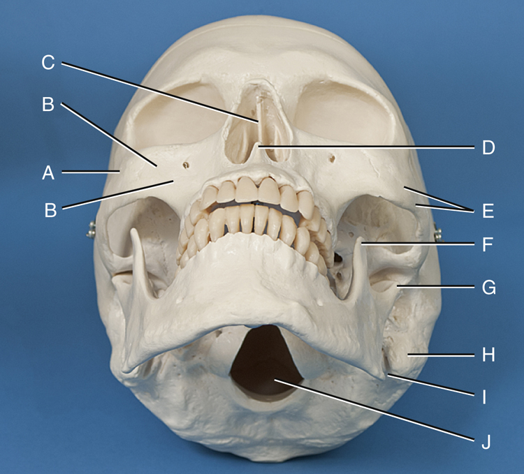
Facial Bones—Frontal View (Fig. 11.82)
- A. Left nasal bone
- B. Frontal process of left maxilla
- C. Optic foramen
- D. Superior orbital fissure
- E. Inferior orbital fissure
- F. Superior and middle nasal conchae of ethmoid bone
- G. Vomer bone (lower portion of bony nasal septum)
- H. Left inferior nasal conchae
- I. Anterior nasal spine
- J. Alveolar process of left maxilla
- K. Alveolar process of left mandible
- L. Mental foramen
- M. Mentum or mental protuberance
- N. Body of right mandible
- O. Angle (gonion) of right mandible
- P. Ramus of right mandible
- Q. Body of right maxilla (contains maxillary sinuses)
- R. Zygomatic prominence of right zygomatic bone
- S. Outer orbit portion of right zygomatic bone
- T. Sphenoid bone (cranial bone)


Clinical Indications: Cranium
Skull and Cranial Pathology
Indications for skull and cranial radiographic procedures have markedly decreased because CT or MRI is increasingly available. However, smaller hospitals, clinics, and rural centers may still perform these procedures.
NOTE:Although radiographic images of the skull provide excellent spatial resolution of bone, the presence or absence of a fracture is in no way an indication of underlying brain injury. Additional imaging procedures (i.e., CT or MRI) must be performed if brain tissue is to be fully assessed.
-
- • Linear fractures are fractures of the skull that may appear as jagged or irregular lucent lines that lie at right angles to the axis of the bone.
- • Depressed fractures are sometimes called ping-pong fractures. A fragment of bone that is separated and depressed into the cranial cavity can occur. A tangential view may be used to determine the degree of depression if CT is unavailable.
- • Basal skull fractures are fractures through the dense inner structures of the temporal bone. These fractures are very difficult to visualize because of the complexity of the anatomy in this area. If bleeding occurs, radiographic images may reveal an air-fluid level in the sphenoid sinus if a horizontal ray is used for the lateral skull projection. CT is the modality of choice to differentiate between epidural and subdural hemorrhage.
- Gunshot wounds can be visualized by radiographic images typically performed to localize bullets in gunshot victims in an antemortem or postmortem examination. The bullet is easily recognizable because of lead content.
- Neoplasms are new and abnormal growths.
-
- • Metastases are primary malignant neoplasms that spread to distant sites via blood and the lymphatic system. The skull is a common site of metastatic lesions, which may be characterized and visualized on the image as follows:
- • Osteolytic lesions are destructive lesions with irregular margins.
- • Osteoblastic lesions are proliferative bony lesions of increased density (brightness).
- • Combination osteolytic and osteoblastic lesions have a “moth-eaten” appearance of bone because of the mix of destructive and blastic lesions.
- Multiple myeloma is a condition in which one or more bone tumors originate in the bone marrow. The skull is a commonly affected site.
- Pituitary adenomas are investigated primarily by CT or MRI. Radiographic images may demonstrate enlargement of the sella turcica and erosion of the dorsum sellae, often as an incidental finding.
- Paget disease (osteitis deformans) is a disease of unknown origin that begins as a stage of bony destruction followed by bony repair. It involves many bony sites, including the skull, pelvis, spine, and lower limbs. Radiographically, areas of lucency demonstrate the destructive stage, and a “cotton-wool” appearance with irregular areas of increased density (sclerosis) shows the reparative stage. Often these regions of bone become fragile and deformed. Nuclear medicine scans can demonstrate both regions of no (cold) and increased (hot) uptake of the radionuclide based on the stage of the disease.
Temporal Bone Pathology
Common pathologic indications for temporal bone radiographic procedures include the following.
- Acute mastoiditis (mas″-toid-i′-tis) is a bacterial infection of the mastoid process that can destroy the inner part of the mastoid process. It often results from middle ear infections. Bacteria in the middle ear can migrate to the mastoids. Mastoid air cells are replaced with a fluid-filled abscess, which can lead to progressive hearing loss. A CT scan demonstrates a fluid-filled abscess that replaces air-filled mastoid air cells.
- Neoplasms are new and abnormal growths (tumors).
-
- • Acoustic neuroma (vestibular schwannoma) refers to a benign, usually slow-growing tumor of the auditory nerve sheath that originates in the internal auditory canal. Symptoms include hearing loss, dizziness, and loss of balance. It typically is diagnosed with the use of CT or MRI (preferred modality), but it may be visualized on radiographic images in advanced cases with expansion and asymmetry of the affected internal acoustic canal.
- • Cholesteatoma (ko″-le-ste″-a-to′-ma) is a benign, cystic mass or tumor that is most common in the middle ear. It occurs due to a congenital defect or chronic otitis media. It may destroy surrounding bone, which can lead to serious complications, including hearing loss. Surgery is required to remove a cholesteatoma. 4
- A polyp is a growth that arises from a mucous membrane and projects into a cavity (sinus). It may cause chronic sinusitis.
- Otosclerosis (o″-to-skle-ro′-sis) is a hereditary disease that involves irregular ossification of the auditory ossicles of the middle ear. One common finding is fixation of the stapes to the oval window (eardrum). This leads to an impediment of sound transmission. It is the most common cause of hearing loss in adults without eardrum damage. Symptoms first become evident between the ages of 11 and 30 years. Otosclerosis is more common in women. 5 It is best demonstrated on CT imaging. See Table 11.2 for a summary of clinical indications related to the cranium.
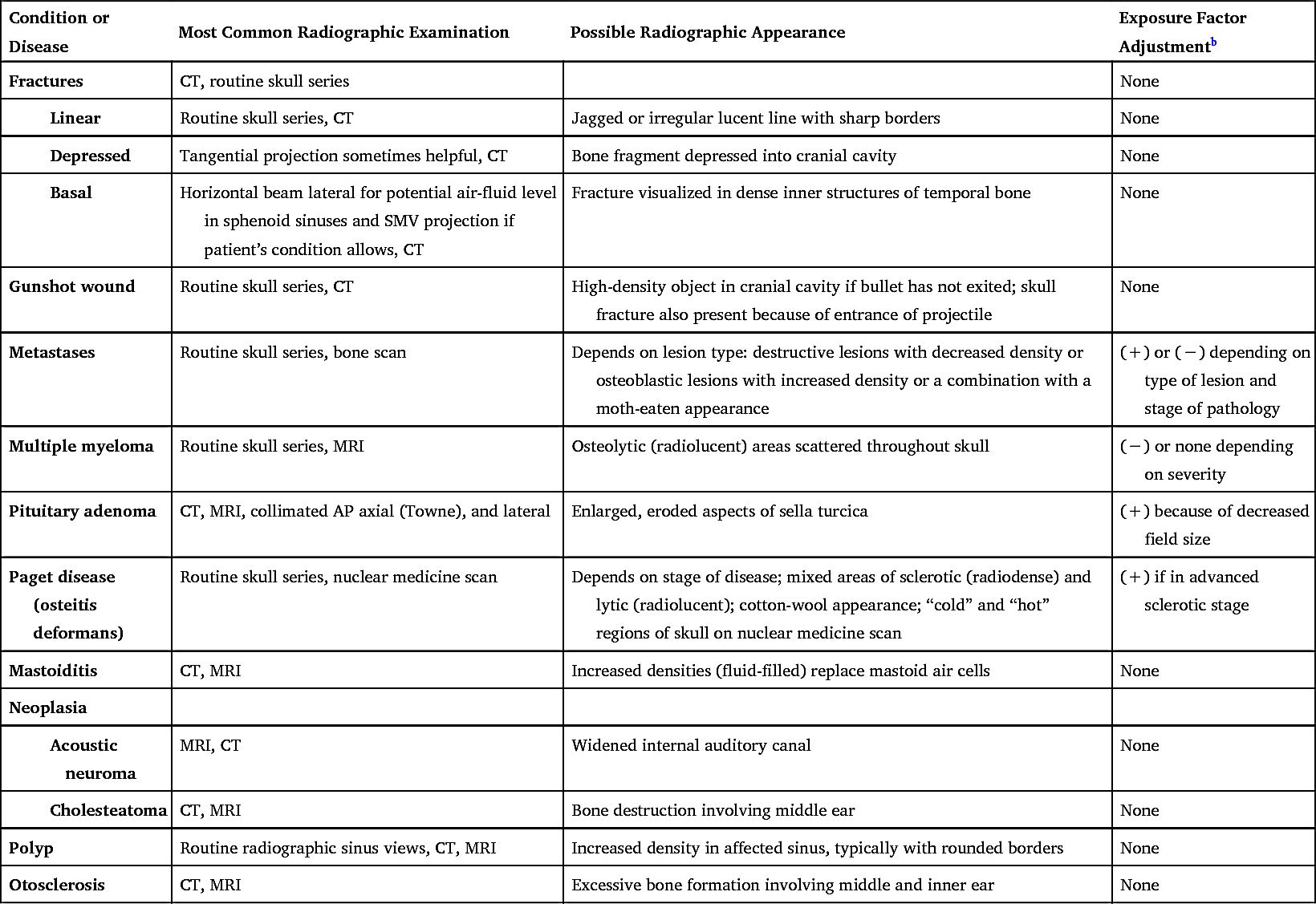
TABLE 11.2
| Condition or Disease | Most Common Radiographic Examination | Possible Radiographic Appearance | Exposure Factor Adjustment b |
|---|---|---|---|
| Fractures | CT, routine skull series | None | |
|
Linear |
Routine skull series, CT | Jagged or irregular lucent line with sharp borders | None |
|
Depressed |
Tangential projection sometimes helpful, CT | Bone fragment depressed into cranial cavity | None |
|
Basal |
Horizontal beam lateral for potential air-fluid level in sphenoid sinuses and SMV projection if patient’s condition allows, CT | Fracture visualized in dense inner structures of temporal bone | None |
| Gunshot wound | Routine skull series, CT | High-density object in cranial cavity if bullet has not exited; skull fracture also present because of entrance of projectile | None |
| Metastases | Routine skull series, bone scan | Depends on lesion type: destructive lesions with decreased density or osteoblastic lesions with increased density or a combination with a moth-eaten appearance | (+) or (−) depending on type of lesion and stage of pathology |
| Multiple myeloma | Routine skull series, MRI | Osteolytic (radiolucent) areas scattered throughout skull | (−) or none depending on severity |
| Pituitary adenoma | CT, MRI, collimated AP axial (Towne), and lateral | Enlarged, eroded aspects of sella turcica | (+) because of decreased field size |
| Paget disease (osteitis deformans) | Routine skull series, nuclear medicine scan | Depends on stage of disease; mixed areas of sclerotic (radiodense) and lytic (radiolucent); cotton-wool appearance; “cold” and “hot” regions of skull on nuclear medicine scan | (+) if in advanced sclerotic stage |
| Mastoiditis | CT, MRI | Increased densities (fluid-filled) replace mastoid air cells | None |
| Neoplasia | |||
|
Acoustic neuroma |
MRI, CT | Widened internal auditory canal | None |
|
Cholesteatoma |
CT, MRI | Bone destruction involving middle ear | None |
| Polyp | Routine radiographic sinus views, CT, MRI | Increased density in affected sinus, typically with rounded borders | None |
| Otosclerosis | CT, MRI | Excessive bone formation involving middle and inner ear | None |
Clinical Indications: Facial Bones and Paranasal Sinuses
In addition to CT or MRI procedures, conventional radiographic examinations for the facial bones and paranasal sinuses still are commonly performed in smaller hospitals and clinics. For paranasal sinuses, radiographs are performed to demonstrate pathologies such as mucosal thickening, air-fluid levels, or erosion of bony margins of the sinuses.
Common clinical indications for various types of radiographic examinations for the facial bones and sinuses include the following:
- Fracture is a break in the structure of a bone caused by a direct or indirect force. Examples of specific fractures involving the facial bones include the following:
-
- • Blowout fracture is a fracture of the floor of the orbit caused by an object striking the eyes straight on (Fig. 11.83). As the floor of the orbit ruptures, the inferior rectus muscle is forced through the fracture into the maxillary sinus, causing entrapment and diplopia (perception of two images). A blowout fracture may also involve the medial walls of the orbit. CT is an effective imaging modality in demonstrating blowout fractures (Fig. 11.84).
- • Tripod fracture is caused by a blow to the cheek, resulting in fracture of the zygoma in three places—orbital process, maxillary process, and arch. The result is a “free-floating” zygomatic bone, or a tripod fracture (Fig. 11.85).
- • Le Fort fractures are severe bilateral horizontal fractures of the maxillae that may result in an unstable detached fragment.
- • Contrecoup fracture is a fracture to one side of a structure that is caused by an impact on the opposite side. For example, a blow to one side of the mandible results in a fracture on the opposite side.
- Foreign body of the eye refers to metal or other types of fragments in the eye, a relatively common industrial mishap. Radiographic images are taken to detect the presence of a metallic foreign object but are limited in their ability to demonstrate damage to tissues caused by these objects.
- The patient interview before an MRI procedure includes questions regarding the history of a foreign object in the eye. Because the magnetic field causes the metal, ferrous fragments to move, injury occurs to the soft tissues (even blindness may occur if the optic nerve is damaged). Radiographic images may be obtained before MRI to confirm the presence of a foreign object.
- Neoplasm describes a new and abnormal growth (tumor) that may occur in the skeletal structures of the face.
- Osteomyelitis is a localized infection of bone or bone marrow. This infection may be caused by bacteria from a penetrating trauma or postoperative or fracture complications. It also may be spread by blood from a distant site.
- Sinusitis (si-nu-si′-tis) is an infection of the sinus mucosa that may be acute or chronic. The patient complains of headache, pain, swelling over the affected sinus, and possibly a low-grade fever.
- Secondary osteomyelitis, an infection of the bone and marrow secondary to sinusitis, results in erosion of the bony margins of the sinus.
- TMJ syndrome describes a set of symptoms, which may include pain and clicking, that indicate dysfunction of the TMJ. This condition may be caused by malocclusion, stress, muscle spasm, or inflammation.
See Table 11.3 for a summary of clinical indications related to facial bones and sinuses.


TABLE 11.3
