
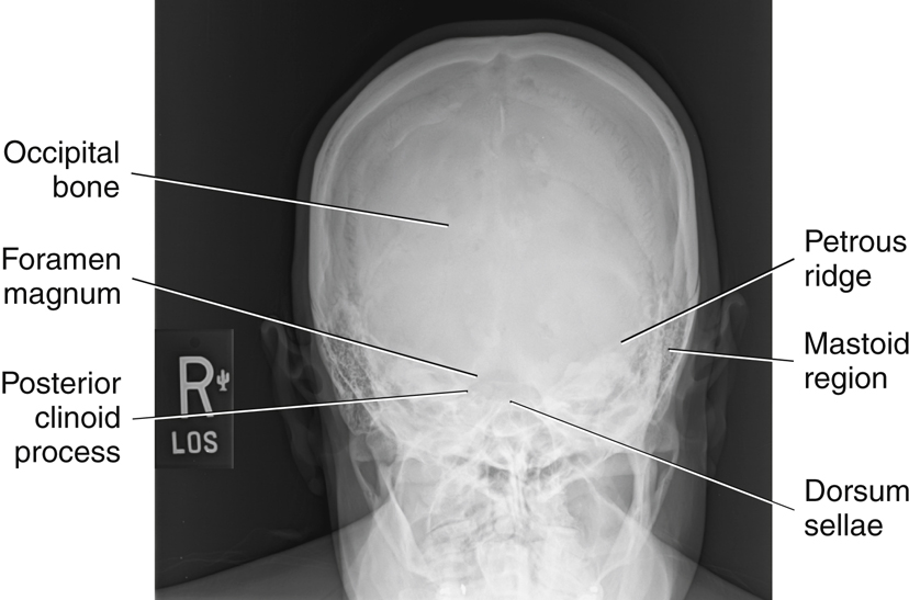
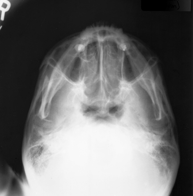
AP Axial Projection—Skull Series
Towne Method
Clinical Indications
Technical Factors
Shielding
Shield radiosensitive tissues outside region of interest.
Patient Position
Remove all metal, plastic, or other removable objects from the patient’s head. Take radiograph with the patient in the erect or supine position.
Part Position

- • Depress chin, bringing OML perpendicular to IR. For patients unable to flex the neck to this extent, align IOML perpendicular to IR. Add radiolucent support under the head if needed (see NOTE).
- • Align MSP to CR and to midline of the grid or the table/imaging device surface.
- • Ensure that no head rotation or tilt exists.
- • Ensure that the vertex of the skull is within collimation field.
CR
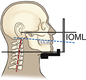
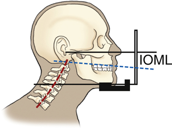
- • Angle CR 30° caudad to OML or 37° caudad to IOM (Fig. 11.107) (see NOTE).
- • Center at MSP 2½ inches (6.5 cm) above the glabella to pass through the foramen magnum at the level of the base of the occiput.
- • Center IR to projected CR.
Recommended Collimation
Collimate on four sides to anatomy of interest.
Respiration
Suspend respiration.
NOTE:If patient is unable to depress the chin sufficiently to bring OML perpendicular to IR even with a small sponge under the head, IOML can be placed perpendicular instead and the CR angle increased to 37° caudad. This maintains the 30° angle between OML and CR and demonstrates the same anatomic relationships. (A 7° to 8° difference exists between OML and IOML.)
Evaluation Criteria
Anatomy Demonstrated:
Position:
- • Petrous ridges should be symmetric, indicating no rotation (petrous ridge will appear narrowed in the direction of rotation).•Dorsum sellae and posterior clinoid processes visualized in the foramen magnum indicate correct CR angle and proper neck flexion/extension.•Underangulation of CR or insufficient flexion of neck projects the dorsum sellae superior to the foramen magnum. Overangulation of CR or excessive neck flexion superimposes the posterior arch of C1 over the dorsum sellae within the foramen magnum and produces foreshortening of the dorsum sellae.•Shifting of the anterior or posterior clinoid processes laterally within the foramen magnum indicates tilt. 7 •Collimation to area of interest.
Exposure:


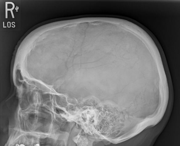
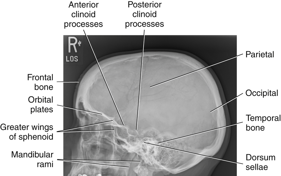
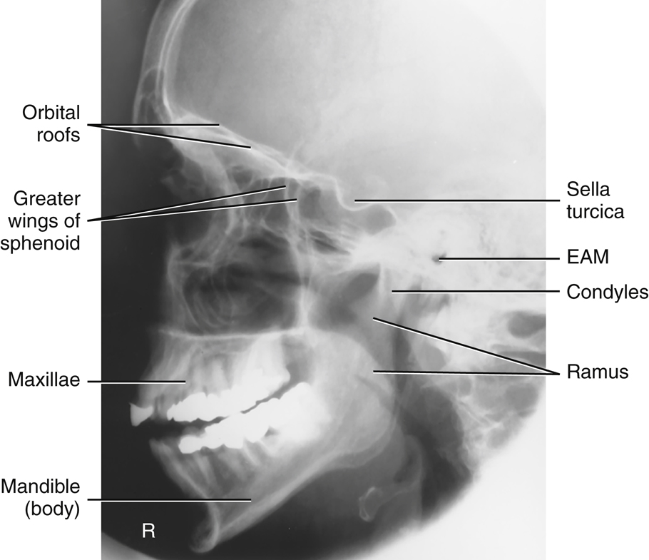
Lateral Position: Right or Left Lateral—Skull Series
Clinical Indications
Trauma Routine
A horizontal beam projection is required to obtain a lateral perspective for trauma patients. This may demonstrate air-fluid levels in the sphenoid sinus—a sign of a basal skull fracture if intracranial bleeding occurs. See Chapter 15 for details on trauma skull projections.
Technical Factors

Shielding
Shield radiosensitive tissues outside region of interest.
Patient Position
Remove all metal, plastic, or other removable objects from patient’s head. Take radiograph with patient in the erect or recumbent semiprone position.
Part Position
- • Place the head in a true lateral position, with the side of interest closest to IR and the patient’s body in a semiprone or erect position as needed for comfort. Align MSP parallel to IR, ensuring no rotation or tilt.
- • Align IPL perpendicular to IR, ensuring no tilt of head (Fig. 11.110) (see NOTE).
- • Adjust neck flexion to align IOML perpendicular to front edge of IR. (GAL is parallel to front edge of IR.)
CR
Recommended Collimation
Collimate on four sides to anatomy of interest.
Respiration
Suspend respiration.
NOTE:For patients in the recumbent position, a radiolucent support placed under the chin helps in maintaining a true lateral position. A patient with a broad chest may require a radiolucent sponge under the entire head to prevent tilt, and a thin patient may require support under the upper thorax.
Evaluation Criteria
Anatomy Demonstrated:
Position:
- • No rotation or tilt of the cranium is evident.•Rotation is evident by anterior and posterior separation of symmetric vertical bilateral structures such as the mandibular rami, and greater wings of the sphenoid.•Tilt is evident by superior and inferior separation of symmetric horizontal structures such as the orbital plates and greater wings of sphenoid bone.•Collimation to area of interest.

Exposure:
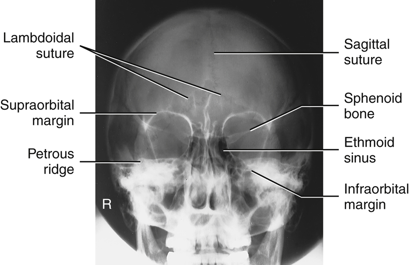
PA Axial Projection—Skull Series
15° CR (Caldwell Method) OR 25° TO 30° CR
Clinical Indications
Technical Factors

Shielding
Shield radiosensitive tissues outside region of interest.
Patient Position
Remove all metallic or plastic objects from the patient’s head and neck. Take radiograph with patient in the erect or prone position.
Part Position
CR
- • Angle CR 15° caudad, and center to exit at nasion (Fig. 11.113).
- • Alternative with CR 25° to 30° caudad, and center to exit at nasion.
Recommended Collimation
Collimate on four sides to anatomy of interest.
Respiration
Suspend respiration.
Alternative 25° to 30°
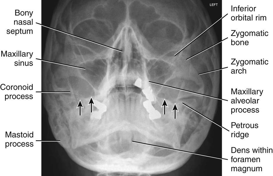
An alternative projection is a 25° to 30° caudad tube angle (Fig. 11.114) that allows better visualization of the superior orbital fissures (black arrows), the foramen rotundum (small white arrows) (Fig. 11.114), and the inferior orbital rim region. CR exits at level of mid orbit.
NOTE:Decreased caudal angulation of the CR to 15° and/or increased neck flexion (chin down) will result in projection of the petrous pyramids to the lower third of the orbits.
Alternative AP Axial Projection
For patients who are unable to be positioned for a PA projection (e.g., trauma patients), an AP axial projection may be obtained with the use of a 15° cephalic angle, with OML positioned perpendicular to IR (see Chapter 15).
Evaluation Criteria
Anatomy Demonstrated:
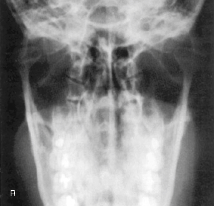
- • Frontal bone, greater and lesser sphenoid wings, superior orbital fissures, frontal and anterior ethmoid sinuses, supraorbital margins, and crista galli are demonstrated (Fig. 11.115).
PA Axial 25° to 30° Caudad Angle
- • In addition to the structures mentioned previously, the foramen rotundum adjacent to each IOM is visualized, and the superior orbital fissures (see Fig. 11.114, white and black arrows) are visualized within the orbits.
Position:
- • No rotation as assessed by equal distance from the midlateral orbital margins to the lateral cortex of the cranium on each side and the superior orbital fissures symmetric within the orbits, correct extension of neck (OML alignment).•Example: If the distance between the right lateral orbit and lateral cranial cortex is greater than the left side, the face is rotated toward the left side.•No tilt with the MSP perpendicular to IR.
PA Axial 15° Caudad Angle:
PA Axial 25° to 30° Caudad Angle:
Exposure:


PA Projection—Skull Series
Clinical Indications
Technical Factors

Shielding
Shield radiosensitive tissues outside region of interest.
Patient Position
Remove all metallic or plastic objects from patient’s head and neck. Exposure is taken with patient in the erect or prone position.
Part Position
CR
- • CR is perpendicular to IR (parallel to OML) and is centered to exit at glabella (Fig. 11.116).
Recommended Collimation
Collimate on four sides to anatomy of interest.
Respiration
Suspend respiration.
Evaluation Criteria
Anatomy Demonstrated:
Position:
- • No rotation is evident, as indicated by equal distance bilaterally from lateral orbital margin to lateral cortex of skull.•Petrous portion of temporal bone fills the orbits with the petrous ridges at the level of the supraorbital margin.•Posterior and anterior clinoid processes are visualized just superior to ethmoid sinuses.•Collimation to area of interest.
Exposure:


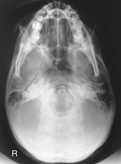
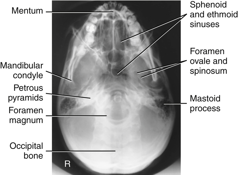
Submentovertical (SMV) Projection—Skull Series
WARNING:Rule out cervical spine fracture or subluxation on trauma patient before attempting this projection.
Clinical Indications
Technical Factors

Shielding
Shield radiosensitive tissues outside region of interest.
Patient Position
Remove all metal, plastic, and other removable objects from patient’s head. Take radiograph with patient in an erect or supine position.
The erect position is recommended using an erect table or an upright imaging device (Fig. 11.119, inset). A wheelchair can also be used. A wheelchair offers support for the back and provides greater stability in maintaining the position. (Ensure wheels are locked before positioning patient.)
Part Position
Supine
With patient in the supine position, extend patient’s head over end of table and support grid cassette and head as shown in Fig. 11.119, keeping IOML parallel to IR and perpendicular to CR. Place a positioning sponge/pillow under the patient’s back to support neck extension.
Erect
If patient is unable to extend the neck sufficiently, compensate by angling CR to remain perpendicular to IOML. Depending on the equipment used, IR also may be angled to maintain the perpendicular relationship with CR (e.g., with an adjustable upright imaging device).
NOTE:This position is very uncomfortable for patients in the erect or the supine position; perform it as quickly as possible.
CR
Recommended Collimation
Collimate on four sides to anatomy of interest.
Respiration
Suspend respiration.

PA Axial Projection—Skull Series
Haas Method
Clinical Indications
This is an alternative projection for patients who cannot flex the neck sufficiently for AP axial (Towne). It can also be performed for hypersthenic and bariatric patients with limited range of cervical motion. It results in magnification of the occipital area but in lower doses to facial structures and the thyroid gland.
This projection is not recommended when the occipital bone is the area of interest because of excessive magnification.
Technical Factors

Shielding
Shield radiosensitive tissues outside region of interest.
Patient Position
Remove all metallic or plastic objects from patient’s head and neck. Take radiograph with patient in the erect or prone position.
Part Position
- • Rest patient’s nose and forehead against the table/imaging device surface.
- • Flex neck, bringing OML perpendicular to IR (Fig. 11.122).
- • Align MSP to CR and to the midline of the grid or table/imaging device surface.
- • Ensure that no rotation or tilt exists (MSP perpendicular to IR).
CR
Recommended Collimation
Collimate on four sides to anatomy of interest.
Respiration
Suspend respiration.
Evaluation Criteria
Anatomy Demonstrated:
Position:
- • No rotation is evident, as indicated by bilateral symmetric petrous ridges.•Dorsum sellae and posterior clinoid processes are visualized in the foramen magnum, which indicates correct CR angle and proper neck flexion and extension.•No tilt as evidenced by correct placement of anterior clinoid processes within the middle of the foramen magnum•Collimation to area of interest.
Exposure:


Lateral Position: Right or Left Lateral—Facial Bones
Clinical Indications
Technical Factors

Shielding
Shield radiosensitive tissues outside region of interest.
Patient Position
Remove all metallic or plastic objects from head and neck. Patient position is erect or recumbent semiprone.
Part Position
- • Rest lateral aspect of head against table or upright imaging device surface, with side of interest closest to IR.
- • Adjust head into a true lateral position and oblique body as needed for patient’s comfort. (Palpate external occipital protuberance posteriorly and nasion or glabella anteriorly to ensure that these two points are equidistant from IR [Fig. 11.125].)
- • Align MSP parallel to IR.
- • Align IPL perpendicular to IR.
- • Adjust chin to bring IOML perpendicular to front edge of IR.
CR
- • Align CR perpendicular to IR.
- • Center CR to zygoma (prominence of the cheek), midway between outer canthus and EAM (Fig. 11.126).
- • Center IR to CR.
Recommended Collimation
Collimate on four sides to anatomy of interest.
Respiration
Suspend respiration.
NOTE:Use radiolucent support under the head if needed to bring IPL perpendicular to tabletop on patient with a large chest.
Evaluation Criteria
Anatomy Demonstrated:
Position:
- • An accurately positioned lateral image of the facial bones demonstrates no rotation or tilt.•Rotation is evident by anterior and posterior separation of symmetric vertical bilateral structures such as the mandibular rami and greater wings of the sphenoid.•Tilt is evident by superior and inferior separation of the orbital plates.•Collimation to area of interest.
Exposure:


Parietoacanthial Projection—Facial Bones
Waters Method
Clinical Indications
Technical Factors

Shielding
Shield radiosensitive tissues outside region of interest.
Patient Position
Remove all metallic or plastic objects from head and neck. Patient position is erect or prone (erect is preferred if patient’s condition allows).
Part Position
- • Extend neck, resting chin against table/upright imaging device surface.
- • Adjust head until MML is perpendicular to plane of IR. OML forms a 37° angle with the table/upright imaging device surface (Fig. 11.129).
- • Position MSP perpendicular to midline of grid or table/imaging device surface, preventing rotation or tilting of head. (One way to check for rotation is to palpate the mastoid processes on each side and the lateral orbital margins with the thumb and fingertips to ensure that these lines are equidistant from the IR.)
CR
Recommended Collimation
Collimate on four sides to anatomy of interest.
Respiration
Suspend respiration.


PA Axial Projection—Facial Bones
Caldwell Method
Clinical Indications
Technical Factors

Shielding
Shield radiosensitive tissues outside region of interest.
Patient Position
Remove all metallic or plastic objects from head and neck. Patient position is erect or prone (erect is preferred if patient’s condition permits it).
Part Position
- • Rest patient’s nose and forehead against the imaging device.
- • Tuck chin, bringing OML perpendicular to IR.
- • Align MSP perpendicular to midline of grid or table/imaging device surface. Ensure no rotation or tilt of head (Fig. 11.132).
CR
Recommended Collimation
Collimate on four sides to anatomy of interest.
Respiration
Suspend respiration.
NOTE:If area of interest is the orbital margins, use a 30° caudad angle to project the petrous ridges below the IOM. CR will exit level of midorbits.
Evaluation Criteria
Anatomy Demonstrated:
Position:
- • Correct patient position/CR angulation is indicated by petrous ridges projected into the lower one-third of orbits with 15° caudad CR. If the inferior orbital margins are the area of interest, 30° caudad angle projects the petrous ridges below the IOMs.•No rotation of cranium is indicated by equal distance from midlateral orbital margin to the lateral cortex of the cranium (a narrower distance would indicate rotation towards the IR); superior orbital fissures are symmetric.•Collimation to area of interest.
Exposure:

Modified Parietoacanthial Projection—Facial Bones
Modified Waters Method
Clinical Indications
Technical Factors

Shielding
Shield radiosensitive tissues outside region of interest.
Patient Position
Remove all metallic or plastic objects from the head and neck. Patient position is erect or prone (erect is preferred if patient’s condition allows).
Part Position
- • Extend neck, resting chin and nose against table/upright imaging device surface.
- • Adjust head until LML is perpendicular; OML forms a 55° angle with IR (Fig. 11.135).
- • Position MSP perpendicular to midline of grid or table/upright imaging device surface. Ensure no rotation or tilt of head.
CR
Recommended Collimation
Collimate on four sides to anatomy of interest.
Respiration
Suspend respiration.


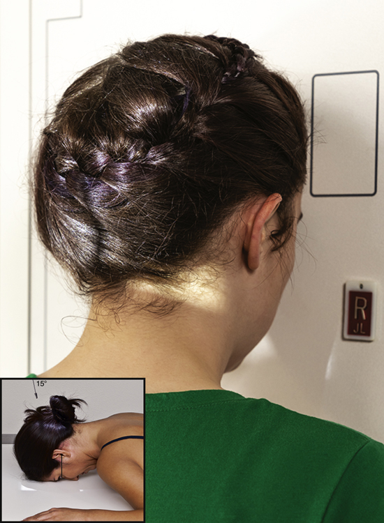
Lateral Position—Nasal Bones
Clinical Indications
Both sides should be examined for comparison, with side closest to IR best demonstrated.
Technical Factors

Shielding
Shield radiosensitive tissues outside region of interest.
Patient Position
Remove all metallic or plastic objects from head and neck. Patient position is recumbent semiprone or erect.
Part Position
- • Rest lateral aspect of head against the table/upright imaging device surface, with side of interest closest to IR.
- • Position nasal bones to center of IR.
- • Adjust head into a true lateral position and oblique body as needed for patient’s comfort (place sponge block under chin if needed) (Fig. 11.138).
- • Align MSP parallel with a table/upright imaging device surface.
- • Align IPL perpendicular to table/upright imaging device surface.
- • Position IOML perpendicular to front edge of IR.
CR
Recommended Collimation
Collimate on all sides to within 2 inches (5 cm) of nasal bone.
Respiration
Suspend respiration.
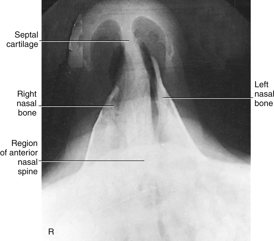
Evaluation Criteria
Anatomy Demonstrated:
- • Nasal bones with soft tissue nasal structures, the region of the frontonasal suture, and the anterior nasal spine are demonstrated (Fig. 11.139).
Position:
Exposure:


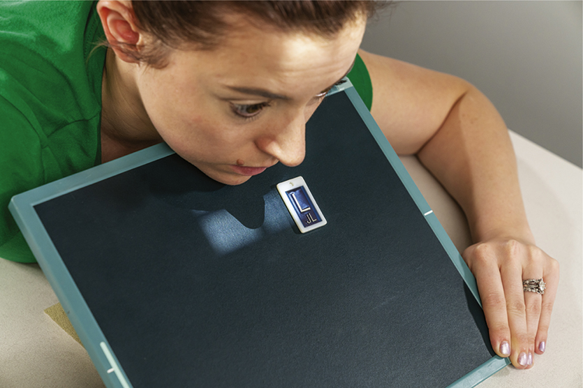
Superoinferior Tangential (Axial) Projection—Nasal Bones
Clinical Indications
Technical Factors

Shielding
Shield radiosensitive tissues outside region of interest.
Patient Position
Patient is seated erect in a chair at end of table or in the prone position on table.
Part Position (insert part position icon here)
- • Extend and rest chin on IR. Place angled support under IR, as demonstrated, to place IR perpendicular to GAL (Fig. 11.140).
- • Align MSP perpendicular to CR and to IR midline.
CR
Recommended Collimation
Collimate on all sides to nasal bones.
Respiration
Suspend respiration.

Submentovertical (SMV) Projection—Zygomatic Arches
Clinical Indications
Technical Factors

Shielding
Shield radiosensitive tissues outside region of interest.
Patient Position
Remove all metallic or plastic objects from head and neck. This projection may be taken with the patient erect or supine.
Part Position
CR
Recommended Collimation
Collimate to outer margins of zygomatic arches.
Respiration
Suspend respiration.
NOTE 1:This position is very uncomfortable for patients; complete the projection as quickly as possible.
NOTE 2:If patient is unable to extend neck adequately, angle CR perpendicular to IOML. If equipment allows, IR should be angled to maintain CR/IR perpendicular relationship (Fig. 11.143, inset).


Oblique Inferosuperior (Tangential) Projection—Zygomatic Arches
Clinical Indications
Radiographs of both sides generally are taken for comparison.
Technical Factors

Shielding
Shield radiosensitive tissues outside region of interest.
Patient Position
Remove all metallic or plastic objects from head and neck. Patient position is erect or supine. Erect, which is easier for the patient, may be done with erect table or upright imaging device.
Part Position
- • Raise chin, hyperextending neck until IOML is parallel to IR (see NOTE 1).
- • Rest head on vertex of skull.
- • Rotate head 15° toward side to be examined; also tilt chin 15° toward side of interest (Fig. 11.146).
CR
Recommended Collimation
Collimate closely to zygomatic bone and arch.
Respiration
Suspend respiration.
NOTE 1:This position is very uncomfortable for the patient; complete the projection as quickly as possible.
NOTE 2:If patient is unable to extend neck sufficiently, angle CR perpendicular to IOML. If equipment allows, IR should be angled to maintain CR/IR perpendicular relationship.

AP Axial Projection—Zygomatic Arches
Modified Towne Method
Clinical Indications
Technical Factors

Shielding
Shield radiosensitive tissues outside region of interest
Patient Position
Remove all metallic or plastic objects from head and neck. Patient position is erect or supine.
Part Position
- • Rest patient’s posterior skull against table/upright imaging device surface.
- • Tuck chin, bringing OML (or IOML) perpendicular to IR (see NOTE).
- • Align MSP perpendicular to midline of grid or table/upright imaging device surface to prevent head rotation or tilt (Fig. 11.149).
CR
Recommended Collimation
Collimate to outer margins of zygomatic arches.
Respiration
Suspend respiration.
NOTE:If patient is unable to depress the chin sufficiently to bring OML perpendicular to IR, IOML can be placed perpendicular instead and CR angle increased to 37° caudad. This positioning maintains the 30° angle between OML and CR and demonstrates the same anatomic relationships. (A 7° to 8° difference is noted between OML and IOML.)


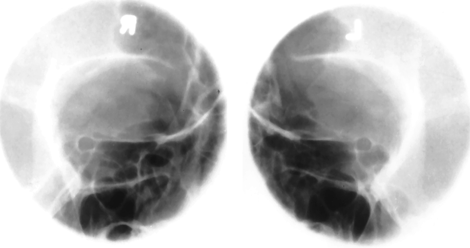
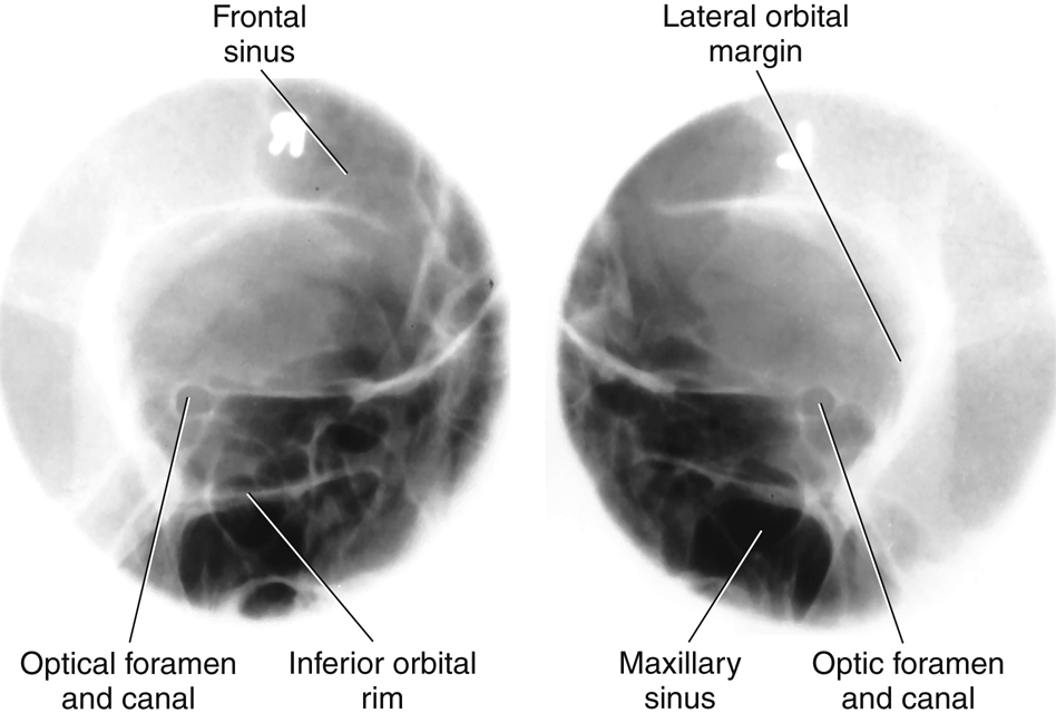
Parieto-Orbital Oblique Projection—Optic Foramina
Rhese Method
Clinical Indications
CT is the preferred modality for a detailed investigation of the optic foramina. Radiographs of both sides generally are taken for comparison. This projection can also provide an excellent image of the midlateral and inferior orbital margins.
Technical Factors

Shielding
Shield radiosensitive tissues outside region of interest.
Patient Position
Remove all metallic or plastic objects from head and neck. Position patient erect or supine.
Part Position
- • As a starting reference, position patient’s head in a prone position with MSP perpendicular to IR. Adjust flexion and extension so that AML is perpendicular to IR. Adjust the patient’s head so that the chin, cheek, and nose touch the table/upright imaging device surface (this position is historically known as the “3 point landing”).
- • Rotate the head 37° toward the affected side. The angle formed between MSP and plane of IR measures 53° (Fig. 11.152). (An angle indicator should be used to obtain an accurate angle of 37° from CR to MSP.)
CR
Recommended Collimation
Collimate on all sides to yield a field size of approximately 3 inches (7.5 cm) square.
Respiration
Suspend respiration during exposure.

Axiolateral or Axiolateral Oblique Projection—Mandible
Clinical Indications
Both sides of mandible are examined for comparison.
Technical Factors

Shielding
Shield radiosensitive tissues outside region of interest.
Patient Position
Remove all metallic or plastic objects from head and neck. Patient position is erect or recumbent. If performed recumbent, place IR on wedge sponge to minimize OID (Fig. 11.155). For erect position, place region of interest against wall bucky and parallel to IR (Fig. 11.156). For horizontal beam trauma position, place IR (and grid if used) parallel to mandible (Fig. 11.157).
Part Position
- • Place head in a true lateral position, with side of interest against IR.
- • If possible, have patient close mouth and bring teeth together.
- • Extend neck slightly to prevent superimposition of the gonion over the cervical spine.
- • Rotate head toward IR (for axiolateral oblique) to place the mandibular area of interest parallel to IR. The degree of rotation/obliquity depends on which section of the mandible is of interest.
- • Head in true lateral position best demonstrates ramus.
- • 10° to 15° rotation best provides a general survey of the mandible.
- • 30° rotation toward IR best demonstrates body.
- • 45° rotation best demonstrates mentum.
CR
Recommended Collimation
Collimate on four sides to anatomy of interest.
Respiration
Suspend respiration.


PA or PA Axial Projection—Mandible
Clinical Indications
Optional PA axial best demonstrates proximal rami and elongated view of condyloid processes.
Technical Factors

Shielding
Shield radiosensitive tissues outside region of interest.
Patient Position
Remove all metallic or plastic objects from head and neck. Patient position is erect or prone.
Part Position
- • Rest patient’s forehead and nose against table/upright imaging device surface (Fig. 11.160).
- • Tuck chin, bringing OML perpendicular to IR (see NOTE).
- • Align MSP perpendicular to midline of grid or table/imaging device surface (ensuring no rotation or tilt of head).
- • Center IR to projected CR (to junction of lips).
CR
Recommended Collimation
Collimate on four sides to anatomy of interest.
Respiration
Suspend respiration.
NOTE:For a true PA projection of the body (if this is area of interest), raise chin to bring AML perpendicular to IR.
Evaluation Criteria
Anatomy Demonstrated:
- • PA: Mandibular rami and lateral portion of body are visible (Fig. 11.161).•Optional PA axial: TMJ region and heads of condyles are visible through mastoid processes; condyloid processes are well visualized (slightly elongated) (Fig. 11.162).
Position:
Exposure:

AP Axial Projection—Mandible
Towne Method
Clinical Indications
Technical Factors

Shielding
Shield radiosensitive tissues outside region of interest.
Patient Position
Remove all metallic or plastic objects from head and neck. Patient position is erect or supine.
Part Position
- • Rest patient’s posterior skull against table/upright imaging device surface.
- • Tuck chin, aligning OML perpendicular to IR or place IOML perpendicular and adjust the CR angle accordingly (see NOTE).
- • Align MSP perpendicular to midline of grid or table/upright imaging device surface to prevent head rotation or tilt.
CR
Recommended Collimation
Collimate on four sides to anatomy of interest.
Respiration
Suspend respiration.
NOTE:If patient is unable to bring OML perpendicular to IR, align IOML perpendicular and increase the 35° CR angle by 7° to 42° caudad (Fig. 11.163). If area of interest is the TM fossae, increase CR angle to 40° to OML to reduce superimposition of TM fossae and mastoid portions of the temporal bone.
Evaluation Criteria
Anatomy Demonstrated:
Position:
- • A correctly positioned image with no rotation demonstrates the following: condyloid processes visualized symmetrically, lateral to the cervical spine; clear visualization of condyle/TM fossae relationship, with minimal superimposition of the TM fossae and mastoid portions (Figs. 11.164 and 11.165).•Collimation to area of interest.
Exposure:


Submentovertical (SMV) Projection—Mandible
Clinical Indications
Technical Factors

Shielding
Shield radiosensitive tissues outside region of interest.
Patient Position
Remove all metallic or plastic objects from head and neck. Patient position is erect or supine (erect preferred, if patient’s condition allows). Erect may be done with an upright imaging device (Fig. 11.166).
Part Position
CR
Recommended Collimation
Collimate on four sides to anatomy of interest.
Respiration
Suspend respiration.
NOTE:If patient is unable to extend the neck sufficiently, angle tube to align CR perpendicular to IOML. This position is very uncomfortable for the patient; complete the projection as quickly as possible.
Evaluation Criteria
Anatomy Demonstrated:
Position:
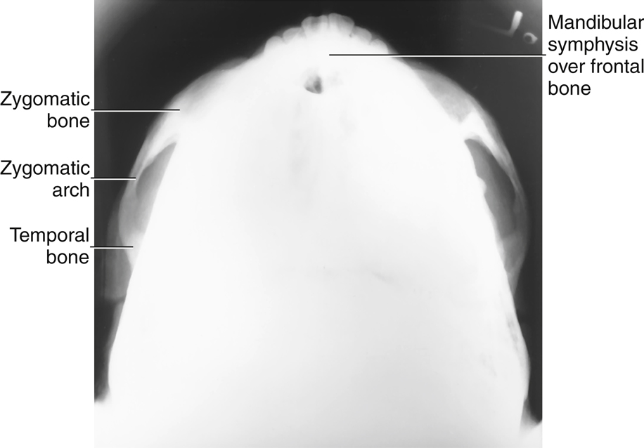
- • Correct neck extension is indicated by the following: mandibular symphysis superimposing frontal bone; mandibular condyles projected anterior to petrous ridges.•No patient rotation or tilt is indicated by the following: no tilt as evidenced by equal distance from mandible to lateral border of skull; no rotation as evidenced by symmetric mandibular condyles.•Collimation to area of interest.
Exposure:


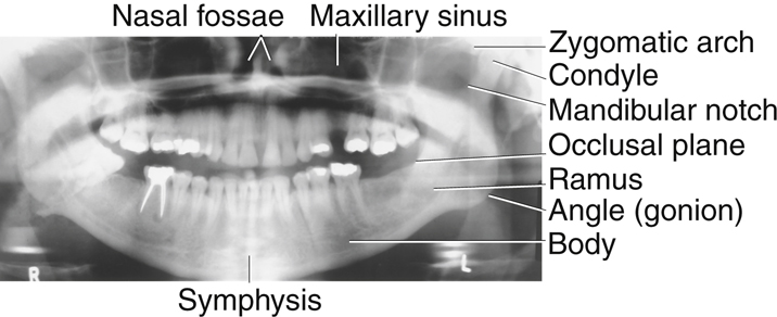
Orthopantomography: Panoramic Tomography—Mandible
Clinical Indications
Technical Factors (Conventional Radiographic Systems)

Unit Preparation
Shielding
Wrap vest-type lead apron around patient.
Patient Position
- • Remove all metal, plastic, and other removable objects from head and neck.
- • Explain to patient how tube and IR rotate and the time span needed for exposure.
- • Guide patient into unit, resting patient’s chin on bite-block (Fig. 11.169).
- • Position patient’s body, head, and neck as demonstrated in Figs. 11.170 and 11.171. Do not allow head and neck to stretch forward (Fig. 11.172); have patient stand with spine straight and hips forward.
Part Position
- • Adjust height of chin rest until IOML is aligned parallel with floor. The occlusal plane (plane of biting surface of teeth) declines 10° from posterior to anterior.
- • Align MSP with vertical center line of chin rest.
- • Position bite-block between patient’s front teeth (see NOTE).
- • Instruct patient to place lips together and position tongue on roof of mouth.
CR
Recommended Collimation
A narrow, vertical-slit diaphragm is attached to tube, providing collimation.
NOTE:When TMJs are of interest, a second panoramic image is taken with the mouth open. This requires placement of a larger bite-block between the patient’s teeth.
Digital Orthopantomography
The first digital orthopantomography system was developed in 1995. Since 1997, digital orthopantomography systems have been replacing the analog systems. These systems do not require a cassette or chemical processing of images. They use a digital detector or a photostimulable phosphor to convert the analog signal into a digitized image. A key advantage of digital orthopantomography over film-based systems is increased exposure latitude and fewer repeat studies. This leads to reduced costs and patient exposure (see Figs. 11.169 and 11.171
).
Advantages of Orthopantomography Compared with Conventional Mandible Positioning
- • More comprehensive image of the mandible, TMJs, surrounding facial bones, and teeth
- • Low patient radiation dose (slit collimation reduces exposure to eyes and thyroid gland)
- • Convenience of examination for patient (one position provides the panoramic view of entire mandible)
- • Ability to image the teeth in a patient who cannot open the mouth or when the oral cavity is restricted
- • Shorter examination time
Evaluation Criteria
Anatomy Demonstrated:
Position:
- • The mandible visualized without rotation or tilting is indicated by the following: TMJs on the same horizontal plane in the image; rami and posterior teeth equally magnified on each side of the image; anterior and posterior teeth sharply visualized with uniform magnification.•Correct positioning of the patient is indicated by the following: mandibular symphysis projected slightly below the mandibular angles; mandible oval in shape; occlusal plane parallel with the long axis of the image; upper and lower teeth positioned slightly apart with no superimposition; cervical spine demonstrated with no superimposition of the TMJs.
Exposure:


AP Axial Projection—Temporomandibular Joints
Modified Towne Method
WARNING:Opening the mouth should not be attempted with possible fracture.
Clinical Indications
See NOTE 1 on open-mouth and closed-mouth comparisons.
Technical Factors

Shielding
Shield radiosensitive tissues outside region of interest.
Patient Position
Remove all metallic or plastic objects from head and neck. Position patient erect or supine.
Part Position
- • Rest patient’s posterior skull against table/upright imaging device surface.
- • Tuck chin, bringing OML perpendicular to table/imaging device surface or bringing IOML perpendicular and increasing CR angle by 7° (Fig. 11.175).
- • Align MSP perpendicular to midline of the grid or the table/upright imaging device surface to prevent head rotation or tilt.
CR
Recommended Collimation
Collimate on four sides to anatomy of interest.
Respiration
Suspend respiration.
NOTE 1:Some departmental protocols indicate that these projections should be taken in both closed-mouth and open-mouth positions for comparison purposes when patient’s condition allows.
NOTE 2:An additional 5° increase in CR may best demonstrate the TM fossae and TMJs.
Evaluation Criteria
Anatomy Demonstrated:
- • Condyloid processes of mandible and TM fossae are demonstrated (Fig. 11.176).
Position:
Exposure:

Axiolateral Oblique Projection—Temporomandibular Joint
Modified Law Method
Clinical Indications
Technical Factors

Shielding
Shield radiosensitive tissues outside region of interest.
Patient Position
Patient position is erect or semiprone (erect is preferred if patient’s condition allows). Rest lateral aspect of head against table/upright imaging device surface, with side of interest closest to IR.
Part Position
- • Prevent tilt by maintaining IPL perpendicular to IR. MSP is parallel to IR to start.
- • Align IOML perpendicular to front edge of IR (Fig. 11.177).
- • From lateral position, rotate face toward IR 15° (with MSP of head rotated 15° from plane of IR).
- • Closed- and open-mouth projections are often taken to demonstrate range of motion of the TMJ (Fig. 11.178).
CR
Recommended Collimation
Collimate on four sides to anatomy of interest.
Respiration
Suspend respiration.


Axiolateral Projection—Temporomandibular Joint
Schuller Method
Clinical Indications
Technical Factors

Shielding
Shield radiosensitive tissues outside region of interest.
Patient Position
Position patient erect or semiprone. Place the head in a true lateral position, with side of interest nearest IR.
Part Position
- • Adjust head into true lateral position and move patient’s body in an oblique direction, as needed for patient’s comfort.
- • Align IPL perpendicular to IR.
- • Align MSP parallel with table/imaging device surface.
- • Position IOML perpendicular to front edge of IR (Fig. 11.181).
Closed- and open-mouth projections are often taken to demonstrate range of motion of the TMJ (Fig. 11.182).
CR
Recommended Collimation
Collimate on four sides to anatomy of interest.
Respiration
Suspend respiration.
Evaluation Criteria
Anatomy Demonstrated:
- • TMJ nearest IR is visible.•Closed-mouth image (Figs. 11.183 and 11.184) demonstrates the condyle within the mandibular fossa; the condyle moves to the anterior margin (articular tubercle) of fossa in the open-mouth position (Fig. 11.185).
Position:
Exposure:


Lateral Position: Right or Left Lateral—Sinuses
Clinical Indications
Technical Factors

Shielding
Shield radiosensitive tissues outside region of interest.
Patient Position
Remove all metal, plastic, and other removable objects from head. Position patient erect (see NOTE).
Part Position
- • Place lateral aspect of head against table/upright imaging device surface, with side of interest closest to IR (Fig. 11.186).
- • Adjust head into true lateral position, moving body in an oblique direction as needed for patient’s comfort (MSP parallel to IR).
- • Align IPL perpendicular to IR (ensures no tilt).
- • Adjust chin to align IOML perpendicular to front edge of IR.
CR
Recommended Collimation
Collimate on four sides to anatomy of interest.
Respiration
Suspend respiration.
NOTE:To visualize air-fluid levels, an erect position with a horizontal beam is required. Fluid within the paranasal sinus cavities is thick and gelatinous, causing it to cling to the cavity walls. To visualize this fluid, allow a short time (at least 5 minutes) for the fluid to settle after patient’s position has been changed (i.e., from recumbent to erect). If patient is unable to be placed in the upright position, the image may be obtained with the use of a horizontal beam, similar to trauma lateral facial bones, as described in Chapter 15.


PA Projection—Sinuses
Caldwell Method
Clinical Indications
Technical Factors

Shielding
Shield radiosensitive tissues outside region of interest.
Patient Position
Remove all metallic or plastic objects from head and neck. Position patient erect (see NOTE).
Part Position
- • Place patient’s nose and forehead against upright imaging device or table with neck extended to elevate OML 15° from horizontal. A radiolucent support between forehead and upright imaging device or table may be used to maintain this position (Fig. 11.189). CR remains horizontal. (See alternative method if imaging device can be tilted 15°.)
- • Align MSP perpendicular to midline of grid or upright imaging device surface.
- • Center IR to CR and to nasion, ensuring no rotation.
CR
Recommended Collimation
Collimate on four sides to anatomy of interest.
Respiration
Suspend respiration.
NOTE:To assess air-fluid levels accurately, CR must be horizontal, and the patient must be erect.
Alternative Method
An alternative method if the imaging device can be tilted 15° is shown (see Fig. 11.189, inset). The patient’s forehead and nose can be supported directly against the imaging device with OML perpendicular to imaging device surface and 15° to horizontal CR.
Evaluation Criteria
Anatomy Demonstrated:
Position:
- • Accurately positioned cranium with no rotation or tilt is indicated by the following: equal distance from the lateral margin of the orbit to the lateral cortex of the cranium on both sides; equal distance from the MSP (identified by the crista galli) to the lateral orbital margin on both sides; superior orbital fissures symmetrically visualized within the orbits.•Correct alignment of OML and CR projects petrous ridges into lower one-third of orbits (black arrows).•Collimation to area of interest.
Exposure:


Parietoacanthial Projection—Sinuses
Waters Method
Clinical Indications
Technical Factors

Shielding
Shield radiosensitive tissues outside region of interest.
Patient Position
Remove all metallic or plastic objects from head and neck. Position patient erect (see NOTE).
Part Position
- • Extend neck, placing chin and nose against table/upright imaging device surface.
- • Adjust head until MML is perpendicular to IR; OML forms a 37° angle with plane of IR (Fig. 11.192).
- • Position MSP perpendicular to midline of grid.
- • Ensure that no rotation or tilt exists.
- • Center IR to CR and to acanthion.
CR
Recommended Collimation
Collimate on four sides to anatomy of interest.
Respiration
Suspend respiration.
NOTE:CR must be horizontal, and patient must be erect to demonstrate air-fluid levels within the paranasal sinus cavities.
Evaluation Criteria
Anatomy Demonstrated:
Position:
- • No rotation of the cranium is indicated by the following: equal distance from MSP (identified by the bony nasal septum) to lateral orbital margin on both sides; equal distance from the lateral orbital margin to the lateral cortex of the cranium on both sides.•Adequate extension of neck demonstrates petrous ridges just inferior to the maxillary sinuses.•Collimation to area of interest.
Exposure:


Submentovertical (SMV) Projection—Sinuses
Clinical Indications
Technical Factors

Shielding
Shield radiosensitive tissues outside region of interest.
Patient Position
Remove all metallic or plastic objects from head and neck. Position patient erect, if possible, to show air-fluid levels.
Part Position
CR
- • CR directed perpendicular to IOML (see NOTE 2).
- • CR centered midway between angles of mandible, at a level 1½ to 2 inches (4 to 5 cm) inferior to mandibular symphysis (Fig. 11.195).
- • CR centered to IR
Recommended Collimation
Collimate on four sides to anatomy of interest.
Respiration
Suspend respiration.
NOTE 1:This position is very uncomfortable for the patient; have all factors set before positioning the patient, and complete the projection as quickly as possible.
NOTE 2:If patient is unable to extend neck sufficiently, angle the tube from horizontal as needed to align CR perpendicular to IOML.
Evaluation Criteria
Anatomy Demonstrated:
Position:
- • Accurate IOML and CR relationship is demonstrated by the following: correct extension of neck and relationship between IOML and CR as indicated by mandibular mentum anterior to ethmoid sinuses.•No rotation evidenced by MSP parallel to edge of IR.•No tilt evidenced by equal distance between mandibular ramus and lateral cranial cortex.•Collimation to area of interest.
Exposure:


Parietoacanthial Transoral Projection—Sinuses
Open-Mouth Waters Method
Clinical Indications
NOTE:This projection is a good alternative to demonstrate the sphenoid sinuses for patients who cannot perform the submentovertex (SMV) position.
Technical Factors

Shielding
Shield radiosensitive tissues outside region of interest.
Patient Position
Remove all metallic or plastic objects from head and neck. Position patient erect.
Part Position
- • Extend neck, placing chin and nose against table/upright imaging device surface.
- • Adjust head until OML forms 37° angle with IR (MML is perpendicular with mouth closed) (Fig. 11.198).
- • Position MSP perpendicular to the midline of grid; ensure no rotation or tilt.
- • Instruct patient to open mouth (i.e., “drop your jaw without moving your head”); MML may not be perpendicular.
- • Center IR to CR and to acanthion.
CR
Recommended Collimation
Collimate on four sides to anatomy of interest.
Respiration
Suspend respiration.
NOTE:Remember, the CR must be horizontal and the patient erect to demonstrate air-fluid levels within the paranasal sinuses.
Evaluation Criteria
Anatomy Demonstrated:
Position:
- • No rotation of the cranium is indicated by the following: equal distance from the MSP (identified by the bony nasal septum) to the lateral orbital margin on both sides; equal distance from the lateral orbital margin to the lateral cortex of the cranium on both sides; accurate extension of the neck demonstrating petrous ridges just inferior to the maxillary sinuses.•Collimation to area of interest.
Exposure:


