Chapter 12: Biliary Tract and Upper Gastrointestinal System
Contributions by Michele Patrícia Müller Mansur Vieira, MSc, TCNL-CRTR-PR (Brazil), Contributors to Past Editions Leslie E. Kendrick, MS, RT(R)(CT)(MR), and Barry T. Anthony, RT(R)
Radiographic Anatomy
Liver
Radiographic examination of the biliary system involves studying the manufacture, transport, and storage of bile. Bile is manufactured by the liver, transported by various ducts, and stored in the gallbladder. Understanding the radiographic examination of the biliary system requires knowledge of the basic anatomy and physiology of the liver, gallbladder, and connecting ducts.
The liver is the largest solid organ in the human body and weighs 3 to 4 lb (about 1.5 to 2 kg). It occupies most of the right upper quadrant. Of the nine abdominal regions, the liver occupies almost all of the right hypochondrium, a major part of the epigastrium, and a significant part of the left hypochondrium.
As viewed from the front in Fig. 12.1, the liver is triangular in shape. The superior border is the widest portion of the liver, approximately 8 to 9 inches (20 to 23 cm) and is convex to conform to the inferior surface of the right hemidiaphragm.
The right border of the liver is its greatest vertical dimension, approximately 6 to 7 inches (15 to 17.5 cm). In the average person, the right border extends from the diaphragm to just below the body of the tenth rib. The liver is protected by the lower right rib cage. Because the liver is highly vascular and easily lacerated, protection by the ribs is necessary.
The gallbladder is typically nestled centrally in the posterior inferior region of the liver. The distal end of the gallbladder extends slightly below the posterior inferior margin of the liver (Fig. 12.2). The axial abdominal computed tomography (CT) image (Fig. 12.3) demonstrates this typical orientation of the gallbladder in relation to the posterior inferior aspect of the right lobe of the liver.
Lobes of the Liver
The liver is partially divided into two major lobes and two minor lobes. As viewed from the front in Fig. 12.4, only the two major lobes can be seen. A much larger right lobe is separated from the smaller left lobe by the falciform (fal′-si-form) ligament.
The two minor lobes of the liver can be found on the posterior aspect of the right lobe (see Fig. 12.2). The first of these is the small quadrate lobe, which is located on the inferior surface of the right lobe between the gallbladder and the falciform ligament. Just posterior to the quadrate lobe is the caudate lobe, which extends superiorly to the diaphragmatic surface. The large inferior vena cava contours over the surface of this caudate lobe. The midinferior surface includes the hepatic bile ducts, which are described and illustrated on the following page.
Function of the Liver
The liver is a complex organ that is essential to life. The liver performs more than 100 different functions, but the function most applicable to radiographic study is the production of large amounts of bile. It secretes about 1 quart, or 800 to 1000 mL, of bile per day.
The major functions of bile are to aid in the digestion of fats by emulsifying (breaking down) fat globules and in the absorption of fat following its digestion. Bile also contains cholesterol, which is made soluble in the bile by the bile salts.


Gallbladder and Biliary Ducts
The gallbladder and the extrahepatic biliary ducts (located outside of the liver) are shown in Fig. 12.5. Bile is formed in small lobules of the liver and travels by small ducts to the larger right or left hepatic ducts. The right and left hepatic ducts join to continue as the common hepatic duct. Bile is carried to the gallbladder via the cystic duct for temporary storage, or it may be secreted directly into the duodenum via the common bile duct. The common bile duct is joined by the pancreatic duct at the hepatopancreatic sphincter, which empties into the duodenum via the duodenal papilla.
The gallbladder is a pear-shaped sac composed of three parts: fundus, body, and neck (Fig. 12.6). The fundus is the distal end and the broadest part of the gallbladder. The body is the main section of the gallbladder. The neck is the narrow proximal end, which continues as the cystic duct. The cystic duct is 1 to 1½ inches (3 to 4 cm) long and contains several membranous folds along its length. These folds are called the spiral valve, which functions to prevent distention or collapse of the cystic duct.
The normal gallbladder is 2½ to 4 inches (7 to 10 cm) long and approximately 1 inch (2.5 cm) wide. It generally holds 2 to 2½ tablespoons (30 to 40 mL) of bile.
Functions of the Gallbladder
The three primary functions of the gallbladder are (1) to store bile, (2) to concentrate bile, and (3) to contract when stimulated.
- 1. If bile is not needed for digestive purposes, it is stored for future use in the gallbladder.
- 2. Bile is concentrated within the gallbladder as a result of hydrolysis (removal of water). In an abnormal situation, when too much water is absorbed or the cholesterol becomes too concentrated, gallstones (choleliths) may form in the gallbladder. (Cholesterol forms the most common type of gallstones. 1 )
- 3. The gallbladder normally contracts when foods, such as fats or fatty acids, are in the duodenum. These foods stimulate the duodenal mucosa to secrete the hormone cholecystokinin (CCK). Increased levels of CCK in the blood cause the gallbladder to contract and the terminal opening of the common bile duct to relax. In addition, CCK causes increased exocrine activity by the pancreas.
Common Bile Duct
The common bile duct averages approximately 3 inches (7.5 cm) in length and has an internal diameter about the size of a drinking straw. The common bile duct descends behind the superior portion of the duodenum and the head of the pancreas to enter the second or descending portion of the duodenum.
The terminal end of the common bile duct is closely associated with the terminal end of the pancreatic duct (duct of Wirsung) (ver′-soong), as shown in Fig. 12.7.
In about 40% of individuals, these ducts pass into the duodenum as two separate ducts with separate openings. In the remaining 60%, the common bile duct joins the pancreatic duct to form one common passageway through the single papilla into the duodenum.
1
In these individuals, this short, single channel becomes narrower as it passes into the duodenum and is a common site for impaction of gallstones.
1
Some references identify this common passageway as an ampulla, the hepatopancreatic ampulla, or the older term, ampulla of Vater.
Near the terminal opening of this passageway into the duodenum, the duct walls contain circular muscle fiber, termed the hepatopancreatic sphincter, or sphincter of Oddi (od′-e). This sphincter relaxes when levels of CCK increase in the bloodstream. The presence of this ring of muscle causes a protrusion into the lumen of the duodenum termed the duodenal papilla (papilla of Vater).


Gallbladder and Biliary Ducts (Lateral View)
The simplified lateral view drawing in Fig. 12.8 illustrates the relationship of the liver, gallbladder, and biliary ducts as seen from the right side. The gallbladder is anterior to the midcoronal plane, whereas the duct system is more midline. This spatial relationship influences optimal positioning of the gallbladder or the biliary ducts. If it is necessary to place the gallbladder as close to the image receptor (IR) as possible, the prone position would be more appropriate than the supine position. If the primary purpose is to drain the gallbladder into the duct system, the patient would be placed supine to assist this drainage.
Anatomy Review
Radiograph of Gallbladder
The left anterior oblique (LAO) position of the gallbladder in Fig. 12.9 demonstrates the cystic duct and the three major divisions of the gallbladder:
Medical Sonography
Sonography (ultrasound) of the gallbladder provides a noninvasive means of studying the gallbladder and the biliary ducts (Fig. 12.10).
Sonography offers four advantages:
- 1. No ionizing radiation: Sonography is a non–ionizing radiation imaging modality that eliminates radiation exposure to the patient, radiologist, and technologist.
- 2. Detection of small calculi: Sonography can detect small calculi in the gallbladder and biliary ducts.
- 3. No contrast medium: No contrast medium is required with sonography. Therefore, this is an ideal alternative for patients who are sensitive to iodinated contrast agents.
- 4. Less patient preparation: Patient preparation with sonography is greatly reduced compared with other modalities. For sonography, the patient should be NPO (nil per os, meaning “nothing by mouth”) 8 hours before the examination. Sonography provides a quick diagnosis for gallbladder disease, and the physician can make a surgical decision in hours.
Clinical Indications
Gallbladder and Biliary Duct Radiography
Clinical indications for gallbladder diseases include nausea, heartburn, premature full feeling when eating, right upper quadrant (RUQ) discomfort and vomiting. Many abnormal conditions may be demonstrated using various imaging modalities, including the following. It is important for technologists to be familiar with biliary terminology (Table 12.1).


From Roth CG, Deshmukh S. Fundamentals of body MRI, ed 2, Philadelphia, 2017, Elsevier.

TABLE 12.1
Biliary Calculi (Gallstones)
Choledocholithiasis is the presence of stones in the biliary ducts. Biliary stones may form in the biliary ducts or migrate from the gallbladder. These stones often produce a blockage in the ducts. Symptoms include pain, tenderness in the right upper quadrant, jaundice, and sometimes pancreatitis.
Cholelithiasis is the condition of having abnormal calcifications or stones in the gallbladder. Increased levels of bilirubin, calcium, or cholesterol may lead to the formation of gallstones. There are two types of stones, cholesterol and pigment stones; 75% of stones that occur are the cholesterol type. Risk factors for developing gallstones include family history, excessive weight, being over 40 years of age, and being female.
2
Symptoms of cholelithiasis include right upper quadrant pain usually after a meal, nausea, and possibly vomiting. Patients with complete blockage of the biliary ducts may develop jaundice.
Gallstones are primarily composed of cholesterol, making them highly radiolucent; another 25% to 30% are primarily cholesterol and crystalline salts, which also are radiolucent. This leaves a smaller percentage (approximately 20%) of gallstones that are composed of crystalline calcium salts, which are often visible on an abdominal radiographic image without contrast media.
2
Milk calcium bile is the emulsion of biliary stones in the gallbladder. This emulsion buildup of calcium deposits within the gallbladder may be difficult to diagnose during cholangiography. It is seen as a diffuse collection of sandlike calcifications or sediment.
Although drugs have been developed that dissolve these stones, most patients have the gallbladder removed. A laparoscopic technique for removing the gallbladder (cholecystectomy) has greatly reduced the convalescence of the patient.
With sonography, stones within the gallbladder or biliary ducts produce a “shadowing” effect. The shadowing effect is created by the partial blockage of the sound wave as it passes by.
Cholecystitis
Acute or chronic cholecystitis is inflammation of the gallbladder. In acute cholecystitis, often a blockage of the cystic duct restricts the flow of bile from the gallbladder into the common bile duct. The blockage is frequently (95% of cases
2
) due to a stone lodged in the neck of the gallbladder. Over time, the bile begins to irritate the inner lining of the gallbladder, and it becomes inflamed. Symptoms of acute cholecystitis include abdominal pain, tenderness in the right upper quadrant, and fever. Bacterial infection and ischemia (obstruction of blood supply) of the gallbladder may also produce acute cholecystitis. Gas-producing bacteria may lead to a gangrenous gallbladder.
Chronic cholecystitis is almost always associated with gallstones but may also be an outcome of pancreatitis or carcinoma of the gallbladder. Symptoms of right upper quadrant pain, heartburn, and nausea may occur after a meal. Calcified plaques, thickening or calcification of the wall of the gallbladder, may be related to chronic cholecystitis. Chronic cholecystitis may produce repetitive attacks following meals that typically subside in 1 to 4 hours.
Neoplasms
Neoplasms are new growths, which may be benign or malignant. Malignant or cancerous tumors of the gallbladder can be aggressive and spread to the liver, pancreas, or gastrointestinal tract. Neoplasms of the gallbladder are rare. Of the malignant tumors of the gallbladder, 85% are adenocarcinomas, and 15% are squamous cell carcinomas.
3
Common benign tumors of the gallbladder include adenomas and cholesterol polyps.
Approximately 80% of patients with carcinoma of the gallbladder have stones. As the tumor grows, it may obstruct the biliary system. Patients may experience pain, vomiting, and jaundice. Sonography and CT are the best modalities to demonstrate neoplasms of the gallbladder. A stent or drain sometimes needs to be inserted within the common bile duct to provide a pathway to the buildup of bile resulting from obstruction.
Biliary Stenosis
Biliary stenosis is a narrowing of one of the biliary ducts. The flow of bile may be restricted by this condition. In the case of gallstones, the stenosis may prevent the passage of the small gallstones into the duodenum, leading to obstruction of the duct. Cholecystitis and jaundice may result from biliary stenosis. During cholangiography, the common bile duct may appear elongated, tapered, and narrowed. A gallstone lodged at the distal common bile duct often presents a filling defect with a small channel of contrast media passing around it.
Table 12.2 presents a summary of clinical indications for gallbladder and biliary tract radiography.
TABLE 12.2
| Condition or Disease | Most Common Radiographic Examination | Possible Radiographic Appearance | Exposure Factor Adjustment a |
|---|---|---|---|
| Choledocholithiasis (stones in biliary ducts) |
Sonography
MRI
ERCP
Operative cholangiography
|
Enlargement or narrowing of biliary ducts owing to presence of stones | None |
| Cholelithiasis (stones in gallbladder) |
Sonography
MRI
Cholescintigraphy (radionuclide studies)
2
|
Both radiolucent and radiopaque densities seen in the region of the gallbladder; “shadowing” effect with ultrasound; failure to accumulate radionuclide within gallbladder 2 | None |
| Acute cholecystitis |
Sonography
MRI
Cholescintigraphy (radionuclide studies)
2
|
Thickened wall of gallbladder with ultrasound; failure to accumulate radionuclide within gallbladder 2 | None |
| Chronic cholecystitis |
Sonography
MRI
|
Calcified plaques or calcification of wall of gallbladder | None |
| Neoplasms |
Sonography
MRI
CT
|
Mass seen within gallbladder, liver, or biliary ducts; extensive calcification of gallbladder wall | None |
| Biliary stenosis |
Operative cholangiogram
ERCP
|
Elongation, tapering, and narrowing of common bile duct | None |

Digestive System
The digestive system includes the entire alimentary canal and several accessory organs (Fig. 12.11).
Alimentary Canal
The alimentary canal begins at the (1) oral cavity (mouth) and continues as the (2) pharynx, (3) esophagus, (4) stomach, and (5) small intestine; it ends as the (6) large intestine, which terminates as the (7) anus. Anatomy and positioning of (1) the oral cavity through (5) the duodenum are covered in this chapter. The remainder of the small intestine, (6) the large intestine, and (7) the anus are discussed in Chapter 13.
Accessory Organs
Accessory organs of digestion include the salivary glands, pancreas, liver, and gallbladder.
Functions
The digestive system performs the following three primary functions:
- 1. The first primary function is the intake or digestion of food, water, vitamins, and minerals. Food is ingested in the form of carbohydrates, lipids, and proteins. These complex food groups must be broken down, or digested, so that absorption can occur.
- 2. The second function of the digestive system is to absorb digested food particles, along with water, vitamins, and essential elements from the alimentary canal, into the blood or lymphatic capillaries.
- 3. The third function is to eliminate any unused material in the form of semisolid waste products.
Common Radiographic Procedures
Two common radiographic procedures involving the upper gastrointestinal (UGI) system are presented in this chapter. These radiographic examinations involve the administration of a contrast medium.
Esophagography (Study of Pharynx and Esophagus)
Radiographic examination specifically of the pharynx and esophagus is termed esophagography. This procedure studies the form and function of the swallowing aspect of the pharynx and esophagus.
Upper Gastrointestinal Series (Study of Distal Esophagus, Stomach, and Duodenum)
The procedure designed to study the distal esophagus, stomach, and duodenum in one examination is termed an upper gastrointestinal series (UGI, upper GI). A posteroanterior (PA) radiograph from an upper GI series is shown in Fig. 12.12.
Barium sulfate mixed with water is the preferred contrast medium for the entire alimentary canal. The negative density area (appearing white) on the radiograph indicates the stomach and duodenal area filled with barium sulfate contrast medium.

Mouth (Oral Cavity)
The alimentary canal is a continuous hollow tube, beginning with the oral cavity (mouth). The oral cavity and surrounding structures are visualized in the midsagittal plane in Fig. 12.13.
The oral cavity is bordered anteriorly and bilaterally by the inner surfaces of the upper and lower teeth. The roof of the oral cavity is formed by the hard and soft palates. Hanging from the midposterior aspect of the soft palate is a small conical process termed the palatine uvula, commonly referred to simply as the uvula (u′-vu-lah). Most of the floor of the oral cavity is formed by the tongue. The oral cavity connects posteriorly with the pharynx (far′-inks), as described subsequently.
Accessory Organs in Oral Cavity
The salivary glands are accessory organs of digestion associated with the mouth. The teeth and tongue cooperate in chewing movements to reduce the size of food particles and mix food with saliva. These chewing movements, termed mastication (mas″-ti-ka′-shun), initiate the mechanical part of digestion.
Three pairs of glands secrete most of the saliva in the oral cavity (Fig. 12.14). These glands are the (1) parotid (pah-rot′-id), meaning “near the ear,” which is the largest of the salivary glands located just anterior to the external ear; (2) submandibular, sometimes called submaxillary, meaning “below the mandible or maxilla”; and (3) sublingual (sub-ling′-gwal), meaning “below the tongue.”
Saliva is 99.5% water and 0.5% solutes or salts and certain digestive enzymes. The salivary glands secrete 1000 to 1500 mL of saliva daily. Saliva dissolves foods to begin the digestion process. It also contains the enzyme amylase (am′-i-lays), which breaks down starches.
Specific salivary glands secrete a thickened fluid that contains mucus. Mucus lubricates food as it is being chewed so that the food can form into a ball, or bolus, for swallowing. The act of swallowing is termed deglutition (deg″-loo-tish′-un).
NOTE:The salivary glands, especially the parotid glands, may be the site of infection. Mumps is an inflammation and enlargement of the parotid glands caused by a paramyxovirus, which can result in inflammation of the testes in approximately 30% of infected males.
Pharynx
The alimentary canal continues as the pharynx posterior to the oral cavity. The pharynx is about 5 inches (12.5 cm) long and is the part of the digestive tube found posterior to the nasal cavity, mouth, and larynx. Midsagittal and coronal sections of the pharynx, as seen from the side and posterior views, are shown in Fig. 12.15. The three parts of the pharynx are named according to their locations.
The nasopharynx is posterior to the bony nasal septum, nasal cavities, and soft palate. This portion of the pharynx is not part of the digestive system.
The oropharynx is directly posterior to the oral cavity proper. The oropharynx extends from the soft palate to the epiglottis (ep″-i-glot′-is). The epiglottis is a membrane-covered cartilage that moves down to cover the opening of the larynx during swallowing.
The third portion of the pharynx is called the laryngopharynx, or hypopharynx. The laryngopharynx extends from the level of the epiglottis to the level of the lower border of the larynx (level of C6, as described in Chapter 2). From this point, it continues as the esophagus. The trachea is seen anterior to the esophagus.


Cavities That Communicate With Pharynx
The drawing in Fig. 12.16 illustrates seven cavities, or openings, that communicate with the three portions of the pharynx. The two nasal cavities and the two tympanic cavities connect to the nasopharynx. The tympanic cavities of the middle ears connect to the nasopharynx via the auditory or eustachian tubes (not shown in the drawing).
The oral cavity (mouth) connects posteriorly to the oropharynx. Inferiorly, the laryngopharynx connects to the openings of both the larynx and the esophagus.
Deglutition (Swallowing)
Food and fluid travel from the oral cavity directly to the esophagus during the act of swallowing, or deglutition. During swallowing, the soft palate closes off the nasopharynx to prevent swallowed substances from regurgitating into the nose. The tongue prevents this material from reentering the mouth.
During swallowing, the epiglottis is depressed to cover the laryngeal opening like a lid. The vocal folds, or cords, also come together to close off the epiglottis. These actions combine to prevent food and fluid from being aspirated (entering the larynx, trachea, and bronchi).
Respiration is inhibited during deglutition to prevent swallowed substances from entering the trachea and lungs. Occasionally, bits of material pass into the larynx and trachea during deglutition, causing a forceful episode of reflex coughing.
Esophagus
The third part of the alimentary canal is the esophagus. The esophagus is a muscular canal, about 10 inches (25 cm) long and about ½ inch (1 to 2 cm) in diameter, extending from the laryngopharynx to the stomach. The esophagus begins posterior to the level of the lower border of the cricoid cartilage of the larynx (C5 to C6), which is at the level of the upper margin of the thyroid cartilage. The esophagus terminates at its connection to the stomach, at the level of the eleventh thoracic vertebra (T11).
In Fig. 12.17, the esophagus is shown to be located posterior to the larynx and trachea. The spatial relationship of the esophagus to both the trachea and the thoracic vertebrae is an important relationship to remember. The esophagus is posterior to the trachea and just anterior to the cervical and thoracic vertebral bodies.
The descending thoracic aorta is between the distal esophagus and the lower thoracic spine. The heart, within its pericardial sac, is immediately posterior to the sternum, anterior to the esophagus, and superior to the diaphragm.
The esophagus is essentially vertical as it descends to the stomach. This swallowing tube is the narrowest part of the entire alimentary canal. The esophagus is most constricted first at its proximal end, where it enters the thorax, and second where it passes through the diaphragm at the esophageal hiatus, or opening. The esophagus pierces the diaphragm at the level of T10. Just before passing through the diaphragm, the esophagus presents a distinct dilation, as shown in Fig. 12.18.
As the esophagus descends within the posterior aspect of the mediastinum, two indentations are present. One indentation occurs at the aortic arch, and the second is found where the esophagus crosses the left primary bronchus.
The lower portion of the esophagus lies close to the posterior aspects of the heart.


Diaphragmatic Openings
The esophagus passes through the diaphragm slightly to the left and posterior to the midpoint of the diaphragm. Fig. 12.19 represents the inferior surface of the diaphragm and indicates the relative positions of the esophagus, inferior vena cava, and aorta.
The lateral view drawing on the right shows the short abdominal portion of the esophagus below the diaphragm. The abdominal segment of the esophagus, termed the cardiac antrum, measures about ½ inch (1 to 2 cm) in length. The cardiac antrum curves sharply to the left after passing through the diaphragm to attach to the stomach.
The opening between the esophagus and the stomach is termed the esophagogastric junction (cardiac orifice) (see Fig. 12.23). Cardiac is an adjective that denotes a relationship to the heart; the cardiac antrum and the cardiac orifice are located near the heart.
The junction of the stomach and the esophagus normally is securely attached to the diaphragm; thus, the upper stomach tends to follow the respiratory movements of the diaphragm.
Swallowing and Peristalsis
The esophagus contains well-developed skeletal muscle layers (circular and longitudinal) in its upper third, skeletal and smooth muscle in its middle third, and smooth muscle in its lower third. In contrast to the trachea, the esophagus is a collapsible tube that opens only when swallowing occurs. The process of deglutition continues in the esophagus after originating in the mouth and pharynx. Fluids tend to pass from the mouth and pharynx to the stomach, primarily by gravity. A bolus of solid material tends to pass both by gravity and by peristalsis.
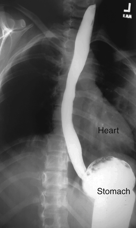
Peristalsis is a wavelike series of involuntary muscular contractions that propel solid and semisolid materials through the tubular alimentary canal. A solid bolus of barium sulfate filling the entire esophagus is seen in Fig. 12.20 descending to the stomach both by gravity and peristalsis. Accumulation of barium in the stomach is seen in this right anterior oblique (RAO) radiograph.
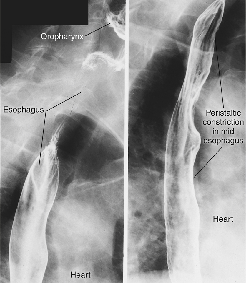
Spot radiographs in an RAO position in Fig. 12.21 demonstrate the esophagus partially filled with barium, with normal peristaltic constrictions most evident in midportions and upper portions of the esophagus.
The relationship of the esophagus to the heart is seen on these radiographs. The esophagus is located immediately adjacent to the right and posterior heart borders.

Stomach
The Greek word gaster means “stomach,” and gastro is a common term denoting stomach—hence the term gastrointestinal tract.
The stomach, which is located between the esophagus and the small intestine, is the most dilated portion of the alimentary canal (Fig. 12.22). When empty, the stomach tends to collapse. When the stomach must serve as a reservoir for swallowed food and fluid, it is remarkably expandable. After a full meal, the stomach stretches to what would appear to be almost the point of rupture.
Because the shape and position of the stomach are highly variable, the average shape and location are used in the following illustrations, with variations to follow later in this chapter.
Stomach Openings and Curvatures
The esophagogastric junction (cardiac orifice) is the aperture, or opening, between the esophagus and the stomach (Fig. 12.23). A small, circular muscle, called the cardiac sphincter, allows food and fluid to pass through the cardiac orifice. This opening (esophagogastric junction) is commonly called the cardiac orifice, which refers to the relationship of this orifice to the portion of the diaphragm near the heart, on which the heart rests.
Directly superior to this orifice is a notch called the cardiac notch (incisura cardiaca). This distal abdominal portion of the esophagus curves sharply into a slightly expanded portion of the terminal esophagus called the cardiac antrum.
The opening, or orifice, of the distal stomach is termed the pyloric orifice, or pylorus. The pyloric sphincter at this orifice is a thickened muscular ring that relaxes periodically during digestion to allow stomach or gastric contents to move into the first part of the small intestine, the duodenum.
The lesser curvature, which is found along the medial border of the stomach, forms a concave border as it extends between the cardiac and pyloric orifices.
The greater curvature is found along the lateral border of the stomach. This greater curvature is four to five times longer than the lesser curvature. It extends from the cardiac notch and the pylorus.
Stomach Subdivisions
The stomach is composed of three main subdivisions: (1) the fundus, (2) the body, and (3) the pylorus (see Fig. 12.23). The fundus is the ballooned portion that lies lateral and superior to the cardiac orifice. The upper portion of the stomach, including the cardiac antrum of the esophagus, is relatively fixed to the diaphragm and tends to move with motion of the diaphragm. In the upright, or erect, position, the fundus is usually filled by a bubble of swallowed air; this is referred to as a gastric bubble.
The lower end of the large body of the stomach has a partially constricted area that separates the body from the pyloric portion of the stomach. This “notch,” or constricted ringlike area, is called the angular notch (incisura angularis).
The smaller terminal portion of the stomach to the right of, or medial to, the angular notch is the pyloric portion of the stomach. The pyloric portion of the stomach frequently is divided into two parts: the pyloric antrum, shown as a slight dilation immediately distal to the angular notch, and the narrowed pyloric canal, which ends at the pyloric sphincter.
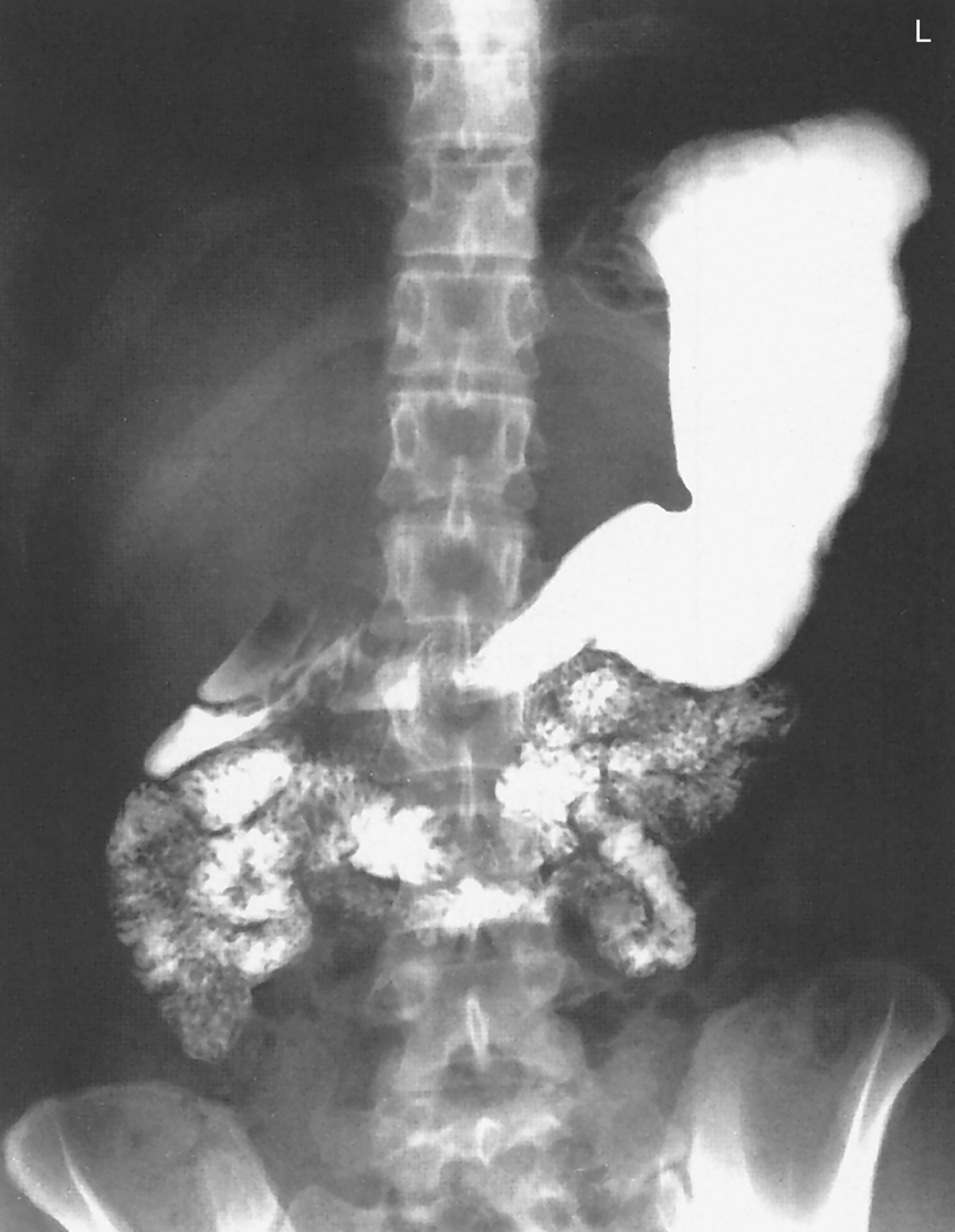
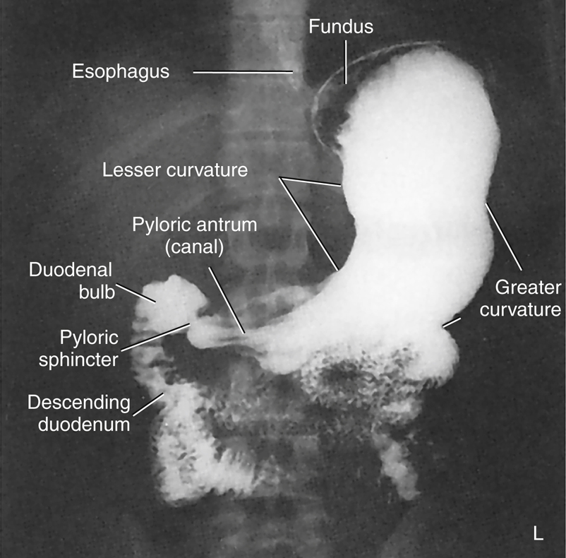
The barium-filled stomach in Fig. 12.24 demonstrates the actual appearance and shape of the stomach, as seen on a PA projection of the stomach and duodenum as part of an upper GI series. Review the labeled parts and compare them with the drawings in Figs. 12.22 and 12.23.


Mucosal Folds Within the Stomach—Rugae
When the stomach is empty, the internal lining is thrown into numerous longitudinal mucosal folds termed rugae ([roo′-je]; singular, ruga [roo′-gah]). Rugae are most evident in the lower body of the stomach along the greater curvature. These folds are shown in the drawing in Fig. 12.25 (they also are demonstrated by the streaklike folds of the air/barium-filled stomach radiograph in Fig. 12.28). The rugae assist with mechanical digestion of food within the stomach.
A gastric canal, formed by rugae along the lesser curvature (see Fig. 12.25), funnels fluids directly from the body of the stomach to the pylorus.
Stomach Position
The illustration in Fig. 12.26 shows the typical orientation of an average, partially filled stomach in anterior and lateral views. The fundus, in addition to being the most superior portion of the stomach in general, is located posterior to the body of the stomach, as can be seen on the lateral view. The body can be seen to curve inferior and anterior from the fundus.
The pylorus is directed posteriorly. The pyloric valve (sphincter) and the first part of the small bowel are very near the posterior abdominal wall. The relationships of these components of the stomach affect the distribution of air and barium within the stomach during specific body positions.
AIR/GAS-Barium Distribution in Stomach
If an individual swallows a barium sulfate and water mixture, along with gas-producing crystals, as seen in Figs. 12.27 and 12.28, the position of the person’s body determines the distribution of barium and air/carbon dioxide (CO2) gas within the stomach.
In the supine position, the fundus of the stomach is the most posterior portion and is where the heavy barium settles (see Fig. 12.27). Note the collection of gas in the body and pylorus of the stomach.
In the RAO, prone position, the fundus is in the highest position, causing the gas to fill this portion of the stomach, as can be seen in Fig. 12.28. The barium settles in the more anterior body and pylorus portions of the stomach.
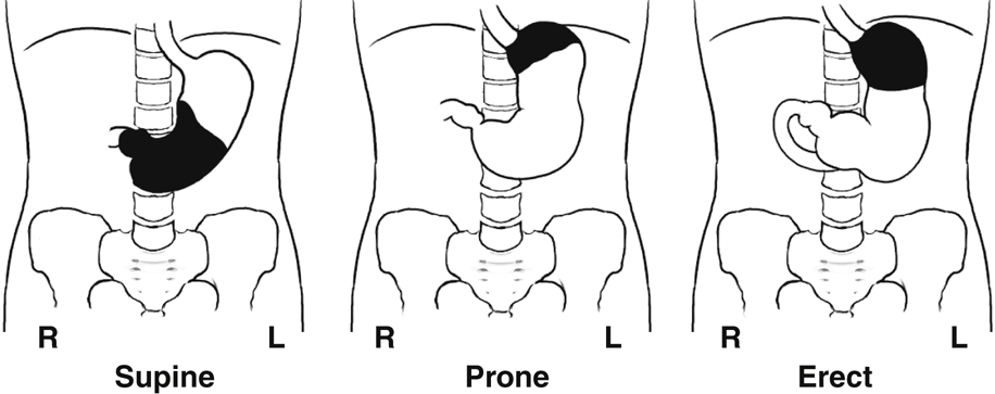
This appearance is also shown in the three position drawings in Fig. 12.29, in which the air/gas is shown as black and the barium as white, similar to the appearance of air and barium in a radiographic image.
The drawing on the left depicts the stomach of a person in supine position. The middle drawing shows the stomach of a person in prone position. The drawing on the right depicts the stomach of a person who is in an erect position. In the erect position, air/gas rises to fill the fundus, whereas barium descends by gravity to fill the pyloric portion of the stomach. The air-barium line tends to be a straight line in the erect position compared with the prone and supine positions.
When studying radiographic images of a stomach that contains both air/gas and barium, you can determine the patient’s position by the relative locations of air versus barium within the stomach.


Duodenum
The fifth and final part of the upper GI system to be studied in this chapter is the duodenum (du″-o-de′-num), which is the first portion of the small intestine, commonly called the small bowel. Because the duodenum is examined radiographically during a routine upper GI series, the duodenum is studied in this chapter; the remainder of the small bowel is studied in Chapter 13 with the lower gastrointestinal system.
The duodenum is about 7½ to 9 inches (20 to 24 cm) long and is the shortest, widest, and most fixed portion of the small intestine. The drawing in Fig. 12.30 demonstrates that the C-shaped duodenum is closely related to the head of the pancreas. The head of the pancreas, nestled in the C-loop of the duodenum, has been affectionately labeled the “romance of the abdomen” by some authors.
The C-loop of the duodenum and the pancreas are retroperitoneal structures; that is, they are located posterior to the parietal peritoneum, as described in Chapter 3.
Four Parts of Duodenum
The duodenum is shaped like the letter C and consists of four parts (Fig. 12.31). The first (superior) portion begins at the pylorus of the stomach. The first part of the superior portion is termed the duodenal bulb, or cap. The duodenal bulb is easily located during barium studies of the upper gastrointestinal tract and must be carefully studied because this area is a common site of ulcer disease. This portion of the duodenum is intraperitoneal; the remainder of the duodenum is retroperitoneal.
The next part of the duodenum is the second (descending) portion, the longest segment. The descending portion of the duodenum possesses the duodenal papilla, which is the opening for the common bile and pancreatic ducts into the duodenum.
The third part of the duodenum is the horizontal portion. This portion curves back to the left to join the final segment, the fourth (ascending) portion of the duodenum.
The junction of the duodenum with the second portion of the small intestine, the jejunum (je-joo′-num), is termed the duodenojejunal flexure. This portion is relatively fixed and is held in place by a fibrous muscular band, the ligament of Treitz (suspensory muscle of the duodenum). This structure is a significant reference point in certain radiographic small bowel studies.
Anatomy Review
Radiograph of Stomach and Duodenum
The PA radiograph of the stomach and duodenum in Fig. 12.32 provides a good review of important radiographic anatomy. Identify the structures labeled on the radiograph, and then compare your answers with the following list.
- A. Distal esophagus
- B. Area of esophagogastric junction (cardiac orifice)
- C. Lesser curvature of stomach
- D. Angular notch (incisura angularis) of stomach
- E. Pylorus of stomach
- F. Pyloric valve or sphincter
- G. Duodenal bulb (cap)
- H. Second (descending) portion of duodenum
- I. Body of stomach
- J. Greater curvature of stomach
- K. Mucosal folds, or rugae, of stomach
- L. Fundus of stomach


Digestion
Mechanical Digestion
Digestion can be divided into a mechanical process and a chemical component. Mechanical digestion includes all movements of the gastrointestinal tract, beginning in the oral cavity (mouth) with chewing, or mastication (mas″-ti-ka′-shun), and continuing in the pharynx and esophagus with swallowing, or deglutition (Table 12.3).
Peristaltic activity can be detected in the lower esophagus and in the remainder of the alimentary canal. The passage of solid or semisolid food from the mouth to the stomach takes 4 to 8 seconds, whereas liquids pass in about 1 second.
The stomach, acting as a reservoir for food and fluid, also acts as a large mixing bowl. Peristalsis moves the gastric contents toward the pyloric valve, but this valve opens selectively. If it is closed, the stomach contents are churned or mixed with stomach fluids into a semifluid mass termed chyme. When the valve opens, small amounts of chyme are passed into the duodenum by stomach peristalsis. Gastric emptying is a slow process, taking 2 to 6 hours for the stomach to empty totally after an average meal. Food with high carbohydrate content leaves the stomach in several hours, whereas food with high protein or fat content moves through much more slowly.
The small intestine (small bowel) continues mechanical digestion with a churning motion within segments of the small bowel. This churning or mixing activity is termed rhythmic segmentation. Rhythmic segmentation is intended to mix food and digestive juices thoroughly. The digested food is also brought into contact with the intestinal lining, or mucosa, to facilitate absorption. Peristalsis is again present to propel intestinal contents along the alimentary canal. However, peristaltic contractions in the small intestine are much weaker and slower than contractions in the esophagus and stomach. Chyme moves through the small intestine at about 1 cm/min. Chyme normally takes 3 to 5 hours to pass through the entire small intestine.
Chemical Digestion
Chemical digestion includes all the chemical changes that food undergoes as it travels through the alimentary canal (Box 12.1). Six different classes of substances are ingested: (1) carbohydrates, or complex sugars; (2) proteins; (3) lipids (lip′-idz), or fats; (4) vitamins; (5) minerals; and (6) water. Only carbohydrates, proteins, and lipids must be chemically digested to be absorbed. Vitamins, minerals, and water are useful in the form in which the body absorbs them.
Chemical digestion is sped up by various enzymes. Enzymes are biologic catalysts found in various digestive juices produced by salivary glands in the mouth and by the stomach, small bowel, and pancreas. These various enzymes are organic compounds, which are proteins. They accelerate chemical changes in other substances without appearing in the final products of the reaction.
Digested Substances and Resultant By-Products
- 1. Carbohydrate digestion of starches begins in the mouth and stomach and is completed in the small intestine. The end products of digestion of these complex sugars are simple sugars.
- 2. Protein digestion begins in the stomach and is completed in the small intestine. The end products of protein digestion are amino acids.
- 3. Lipid, or fat, digestion essentially occurs only in the small bowel, although small amounts of the enzyme necessary for fat digestion are found in the stomach. The end products of lipid digestion are fatty acids and glycerol (glis′-er-ol).
Bile, manufactured by the liver and stored in the gallbladder, is released into the duodenum to assist in the breakdown of lipids (fats). Bile contains no enzymes, but it does emulsify fats. During emulsification, large fat droplets are broken down to small fat droplets, which have greater surface area (to volume) and give enzymes greater access for the breakdown of lipids. The end products of fat (or lipids) during digestion are fatty acids and glycerol.
Most of the absorption of digestive end products occurs in the small intestine. Simple sugars, amino acids, fatty acids, glycerol, water, and most salts and vitamins are absorbed into the bloodstream or the lymphatic system through the lining of the small intestine. Limited absorption takes place in the stomach and may include some water, alcohol, vitamins, and certain drugs but no nutrients. Any residues of digestion or unabsorbed digestive products are eliminated from the large bowel as a component of feces.
TABLE 12.3

Summary
Three primary functions of the digestive system are accomplished within the alimentary canal (Box 12.2).
- 1. Ingestion or digestion takes place in the oral cavity, pharynx, esophagus, stomach, and small intestine.
- 2. Digestive end products, along with water, vitamins, and minerals, are absorbed primarily by the small intestine and to a very small degree by the stomach and are transported into the circulatory system.
- 3. Unused or unnecessary solid material is eliminated by the large intestine. (Digestive functions of the large intestine are described in Chapter 13.)
Body Habitus
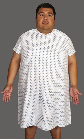
The type of body habitus has a major impact on the location of gastrointestinal organs within the abdominal cavity. To position for gastrointestinal procedures accurately and consistently, one must know and understand the characteristics of each of these classes of body habitus. The four general classes of body habitus are shown in Fig. 12.33.
Body Type Classifications
Hypersthenic Body Type
In the hypersthenic body type (Fig. 12.34), the chest and abdomen are quite broad and deep from front to back. The lungs are short, and the diaphragm is high. The transverse colon is also quite high, and the entire large intestine extends to the periphery of the abdominal cavity. This body type generally requires two radiographs placed landscape to include the entire large intestine.
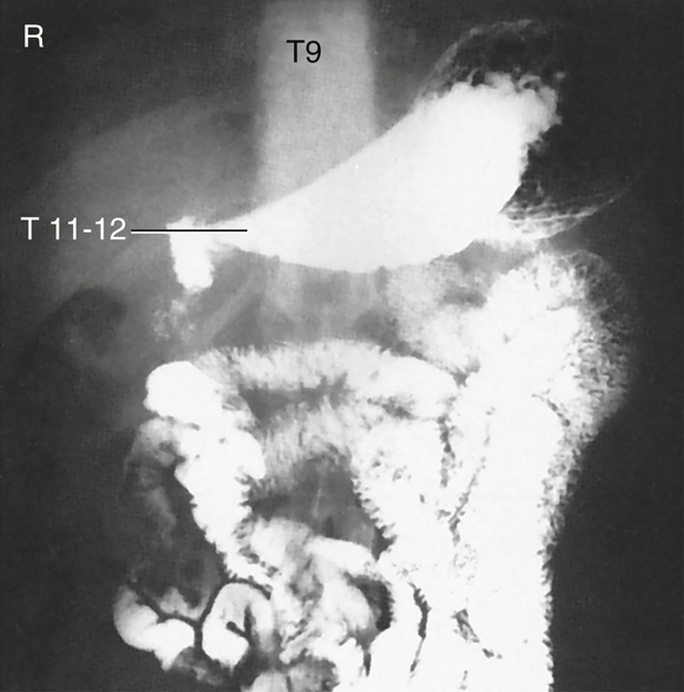
The location of the gallbladder is associated with the duodenal bulb and pylorus region of the stomach. For a hypersthenic patient, the gallbladder is high and almost transverse. It lies well to the right of midline in the upper abdominal cavity. The stomach is also very high and assumes a transverse position. The level of the stomach extends from approximately T9 to T12, with the center of the stomach about 1 inch (2.5 cm) distal to the xiphoid process. The duodenal bulb is at the approximate level of T11 or T12, to the right of midline.
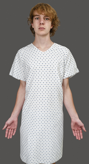
Hyposthenic/Asthenic Body Type
The hyposthenic/asthenic body type is more slender and typically has long, narrow lungs, with a low diaphragm. This pushes the large intestine down into the low abdominal and pelvic cavities.
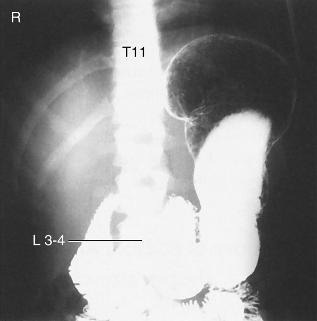
The stomach is J shaped and low in the abdominal cavity, extending from approximately T11 down to L5 or lower. The vertical portion of the stomach is to the left of midline, with the duodenal bulb near the midline at the level of L3 or L4.
The gallbladder is near the midline, at the level of the iliac crest, approximately at L3 to L4.
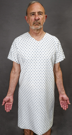
Sthenic Body Type
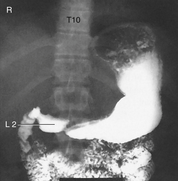
The sthenic body type (Fig. 12.35) is a more slender version of the hypersthenic classification. The stomach is also J shaped and is located lower within the abdominal cavity than in the hypersthenic body type. It generally extends from T11 down to L2. The duodenal bulb is at the approximate level of L1 to L2, to the right of the midline. The gallbladder is less transverse and lies midway between the lateral abdominal wall and midline. The left colic (splenic) flexure of the large intestine is often quite high, resting under the left diaphragm.
Additional Factors
In addition to body habitus, other factors that may affect the position of the stomach include stomach contents, respiration, body position (erect versus recumbent), previous abdominal surgeries, and age. Because the upper stomach is attached to the diaphragm, whether one is in full inspiration or expiration affects the superior extent of the stomach. All abdominal organs tend to drop 1 to 2 inches (2.5 to 5 cm) in an erect position, or even farther with age and loss of muscle tone. As a technologist, correct localization of the stomach and other organs for different body types in various positions comes with positioning practice.


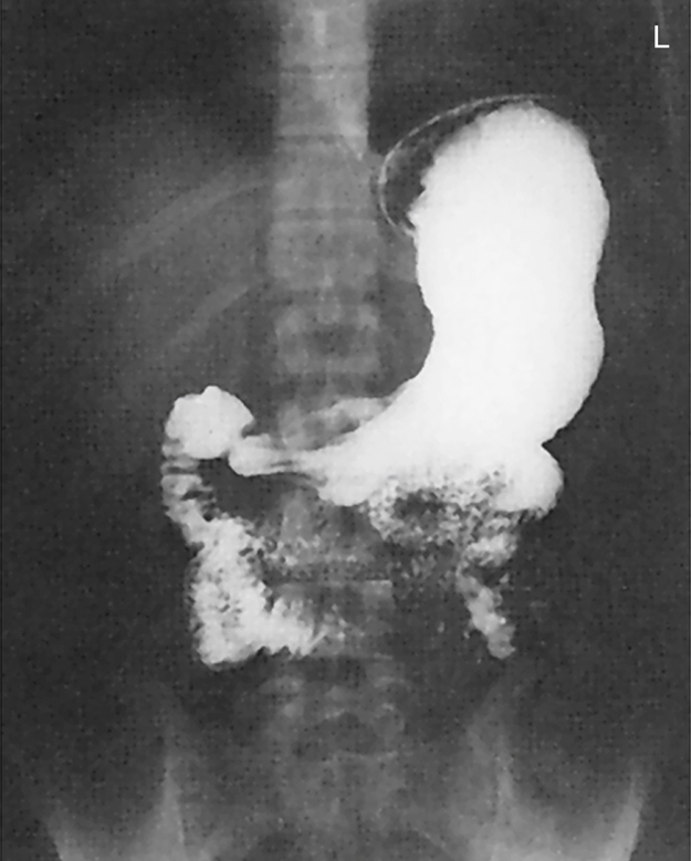
Radiographs of Upper Gastrointestinal Tract Demonstrating Body Types
Most people do not fall clearly into one of the distinct three body types but are a combination of these types. The technologist must be able to evaluate each patient for probable stomach and gallbladder locations.
The radiographic and photographic body type examples demonstrate the position and location of the stomach on the three most common body types (Figs. 12.36 to 12.41). The location of the stomach and duodenal bulb in relation to specific vertebrae should be noted, in addition to the iliac crest and lower costal margin positioning landmarks.
Radiographic Procedures
Similarities
Radiographic procedures or examinations of the entire alimentary canal are similar in three general aspects.
First, because most parts of the gastrointestinal tract are comparable in density with the tissues surrounding them, some type of contrast medium must be added to visualize these structures. Ordinarily, the only parts of the alimentary canal that can be easily identified on plain radiographs are the fundus of the stomach (in the upright position), because of the gastric air bubble, and parts of the large intestine, because of pockets of gas and collections of fecal matter.
Most of the alimentary canal simply blends in with the surrounding structures and cannot be visualized without the use of contrast media. This fact is illustrated by comparison of a noncontrast abdominal radiograph (Fig. 12.42) with an upper GI series radiograph with barium sulfate used as a contrast medium (Fig. 12.43).
A second similarity is that the initial stage of each radiographic examination of the alimentary canal is carried out with fluoroscopy (Fig. 12.44). Fluoroscopy allows the radiologist to (1) observe the gastrointestinal tract in motion, (2) produce radiographic images during the course of the examination, and (3) determine the most appropriate course of action for a complete radiographic examination. Radiographic examination of the upper gastrointestinal tract requires dynamic viewing of organs in motion. The structures in this area assume a wide variety of shapes and sizes, depending on body habitus, age, and other individual differences.
In addition, the functional activity of the alimentary canal exhibits a wide range of differences that are considered within normal limits. In addition to these variations, numerous abnormal conditions exist, making it important that these organs be viewed directly by fluoroscopy.
A third similarity is that radiographic images are recorded during and after the fluoroscopic examination to provide a permanent record of the normal or abnormal findings. In Fig. 12.45, the patient has been positioned for a postfluoroscopic radiograph following fluoroscopic evaluation of the upper gastrointestinal tract. The positioning section of this chapter describes the most common postfluoroscopy routine projections for esophagogram and upper GI procedures.
With increased use of digital fluoroscopy, the number of postfluoroscopy radiographs has diminished greatly. Most departments rely strictly on the digital images produced during the fluoroscopy examination rather than additional postfluoroscopy radiographs. Digital fluoroscopy is described in greater detail later in this chapter.


Contrast Media
Radiolucent and radiopaque contrast media are used to render the gastrointestinal tract visible radiographically.
Radiolucent, or negative, contrast media include swallowed air, CO
2
gas crystals, and the normally present gas bubble in the stomach. Calcium and magnesium citrate carbonate crystals are frequently used to produce CO2 gas.
Barium Sulfate
The most common positive, or radiopaque, contrast medium used to visualize the gastrointestinal system is barium sulfate (BaSO4), which is also referred to simply as barium. As illustrated in Fig. 12.46, barium sulfate is a powdered, chalklike substance. The powdered barium sulfate is mixed with water before ingestion by the patient.
This particular compound, which is a salt of barium, is relatively inert because of its extreme insolubility in water and other aqueous solutions, such as acids. All other salts of barium tend to be toxic or poisonous to the human system. Therefore, the barium sulfate used in radiology departments must be chemically pure. Because it does not interact chemically with the body, it rarely produces an allergic reaction. Barium sulfate eventually is expelled rectally after the radiographic procedure.
A mixture of barium sulfate and water forms a colloidal suspension, not a solution. For a solution, the molecules of the substance added to water must actually dissolve in the water. Barium sulfate never dissolves in water. In a colloidal suspension, the particles suspended in water tend to settle over time when allowed to sit.
Fig. 12.47 shows four cups of different brands of barium that were mixed at a ratio by volume of 1 part water to 1 part barium sulfate. The cups were then allowed to sit for 24 hours. Because different brands of barium sulfate were used, some cups exhibit greater separation or settling than others. This settling demonstrates the need to mix the barium sulfate and water thoroughly just before use.
Most barium sulfate preparations are prepackaged; water is added to the cup followed by mixing. Some barium sulfate preparations come in a liquid form, which does not require water to be added but must still be shaken thoroughly before the procedure is performed. Most of these preparations contain finely divided barium sulfate in a special suspending agent, so they resist settling and stay in suspension longer. However, no matter the manufacturer or packaging, all barium suspensions must be mixed well just before use.
Each brand may come in a variety of smells and flavors, such as apple, chocolate, chocolate malt, vanilla, lemon, lime, or strawberry. This is in an effort to make the barium sulfate more palatable for the patient during the procedure.
Thin Barium
Barium sulfate may be prepared or purchased in a relatively thin or thick mixture. The thin barium sulfate and water mixture contained in a cup, as illustrated in Fig. 12.48, contains 1 part BaSO
4
to 1 part water. Thin barium has the consistency of a thin milkshake and is used to study the entire gastrointestinal tract. Thin barium mixtures, on average, consist of 60% weight-to-volume (w/v) of barium sulfate to water.
The motility, or speed, with which barium sulfate passes through the gastrointestinal tract depends on the suspending medium and additives, the temperature, and the consistency of the preparation, in addition to the general condition of the patient and the gastrointestinal tract. Mixing the preparation exactly according to radiologist preferences and departmental protocol is most important. When the mixture is cold, the chalky taste is much less objectionable.
Thick Barium
Thick barium contains 3 or 4 parts BaSO
4
to 1 part water and should have the consistency of cooked cereal (Fig. 12.49). Thick barium is more difficult to swallow but is well suited for use in the esophagus because it descends slowly and tends to coat the mucosal lining. Some commercially prepared thick barium sulfate may possess a 98% w/v of barium to water.


Contraindications to Barium Sulfate
Barium sulfate mixtures are contraindicated if there is any chance that the mixture might escape into the peritoneal cavity. If large amounts of barium sulfate escape into the peritoneal cavity, this can lead to intestinal infarcts or peritonitis. This escape may occur through a perforated viscus or during surgery that follows the radiographic procedure. In either of these two cases, water-soluble, iodinated contrast media should be used. One example of this type of contrast media is MD-Gastroview, which is shown in Fig. 12.50. This water-soluble contrast agent contains 37% organically bound iodine, which opacifies the gastrointestinal tract. It can be removed easily by aspiration before or during surgery. If any of this water-soluble material escapes into the peritoneal cavity, the body can readily absorb it. Barium sulfate is not absorbed.
One drawback to the water-soluble materials is their bitter taste. Although these iodinated contrast media sometimes are mixed with carbonated soft drinks to mask the taste, they often are used “as is” or diluted with water. The patient should be forewarned that the taste may be slightly bitter.
The technologist should be aware that water-soluble contrast agents travel through the gastrointestinal tract faster than barium sulfate. The shorter transit time of water-soluble contrast agents should be kept in mind if delayed images of the stomach or duodenum are ordered.
WARNING: Water-soluble iodinated contrast media should not be used if the patient is sensitive to iodine, or if the patient is experiencing severe dehydration. A water-soluble contrast agent often further dehydrates the patient. It has also been reported that a small number of patients are hypersensitive to barium sulfate or the additives. Although this is a rare occurrence, the patient should be observed for any signs of allergic reaction.
Double Contrast
Double-contrast techniques have been used widely to enhance the diagnosis of certain diseases and conditions during upper GI series. Some departments also perform double-contrast esophagograms. Double-contrast procedures using both radiolucent and radiopaque contrast media were developed in Japan, where a high incidence of stomach carcinoma exists.
The radiopaque contrast medium is barium sulfate. High-density barium is used to coat the stomach mucosa. A premeasured, commercially produced cup of barium is a common choice for departments to supply. The technologist needs only to add water and mix thoroughly.
The radiolucent contrast medium is either room air or CO
2
gas. To introduce room air, small pinprick holes are placed in the patient’s straw. As the patient drinks the barium mixture, air is drawn in with it.
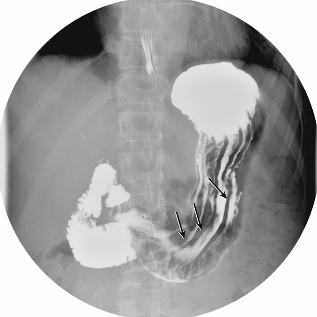
CO2 gas is created when the patient ingests gas-producing crystals. Two common forms of these crystals are calcium and magnesium citrate. On reaching the stomach, these crystals form a large gas bubble. The gas mixes with the barium and forces the barium sulfate against the stomach mucosa, providing better coating and visibility of the mucosa and its patterns (Fig. 12.51). Longitudinal mucosal folds (rugae) of the stomach are indicated by the arrows in Fig. 12.52. Potential polyps, diverticula, and ulcers are better demonstrated with a double-contrast technique.
Postexamination Elimination (Defecation)
One of the functions of the large intestine is to absorb water. Any barium sulfate mixture remaining in the large intestine after an upper GI series or barium enema may become solidified. Consequently, the barium may be difficult to evacuate. Some patients may require a laxative after these examinations to help remove the barium sulfate. If laxatives are contraindicated, the patient should increase fluid or fiber intake until stools are free from all traces of the white barium.


Digital Fluoroscopy
A C-arm digital fluoroscopy unit is shown in Fig. 12.53. In this position, the x-ray tube is on the lower portion of the C-arm, and the image intensifier is on the upper portion. This type of digital fluoroscopy unit is very versatile. It can be rotated around the patient in any position for various types of special procedures, including invasive angiography studies, as described in Chapter 17.
Digital Radiography-Fluoroscopy
A digital radiography-fluoroscopy (R/F) system is shown in Fig. 12.54. This type of combination radiography-fluoroscopy system is commonly used for gastrointestinal procedures. The digital R/F system incorporates digital fluoroscopy capabilities with a conventional type of x-ray table and an “under-the-table” fluoroscopy x-tube. It also includes a separate radiography tube for conventional “overhead” radiography applications.
Digital fluoroscopy is similar to conventional fluoroscopy with the addition of a flat panel detector and a computer for image manipulation and storage. A thin film transistor is incorporated within the system to convert the x-ray energy into a digital signal. From there, the image information is transferred to a computer for manipulation and storage. The system’s hard drive stores a limited number of images. When the examination is completed, these images are sent to a Picture Archiving and Communication System (PACS) or are printed via a laser printer.
A computer workstation provides software capabilities for image manipulations. Images can be displayed on high-resolution monitors for evaluation or interpretation. The use of digital fluoroscopy permits gastrointestinal studies to remain in a digital format that can be sent to various locations inside and outside the hospital. Digital fluoroscopy has led to the expanded use of PACS, which is a digital imaging network that provides the ability to store, retrieve, manipulate, and print specific examinations at various locations. As described in greater detail in Chapter 1, PACS ties together all digital imaging modalities, such as ultrasound, nuclear medicine, magnetic resonance imaging (MRI), and radiography, into a digital community where radiologists, technologists, and referring physicians can access these images. The concept of the “film room” is becoming obsolete.


Optional Postfluoroscopy Images
The question of whether to take images routinely after fluoroscopy is decided by the radiologist or by departmental protocol. Frequently, sufficient digital images are recorded of the entire gastrointestinal tract in various positions during fluoroscopy that no postfluoroscopy images are required. Elimination of these images can result in decreased examination times and patient exposure for upper and lower GI series procedures.
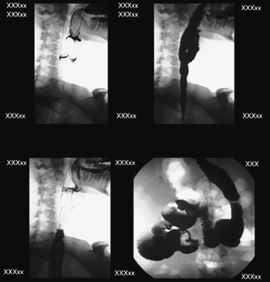
Multiple Frame Formatting and Multiple “Original” Films
If requested, multiple images can be formatted and printed on one piece of laser film. This format can be 4 on 1 (Fig. 12.55), 6 on 1, 9 on 1, or 12 on 1. “Hard copy” films can be printed at any time and as often as desired. If radiographs are lost or misplaced or if duplicates are needed, additional “original” films can be reprinted at any time.
Cine Loop Capability
Individual images also can be recorded in rapid succession and displayed as moving or cine images. This feature is beneficial for certain studies, such as an esophagogram for possible esophageal reflux or impaired swallowing mechanisms. This capability has replaced the need for spot film cameras or video recording. When the study has been completed, the technologist can play back the cine loop to demonstrate the dynamic flow of barium through the esophagus or stomach. The radiologist can interpret the study from a monitor located in an office or reading room.
Image Enhancement and Manipulation
Digital fluoroscopy images can be enhanced and manipulated with the use of post-processing tools (Figs. 12.56 and 12.57). These image enhancement and manipulation features include edge enhancement, window and leveling, dynamic range control, and dual energy subtraction. Other options include inverting the image contrast, motion artifact control, and smoothing. With the study saved on the hard disk, the technologist or radiologist has the ability to alter these imaging parameters at will.


Worker Protection During Fluoroscopy
Radiation protection practices during fluoroscopy are described in Chapter 1.
Exposure Patterns
Exposure patterns and related doses within the fluoroscopy room, indicating where one should stand or not stand in the room during fluoroscopy, also are provided in Chapter 1. Fig. 12.58 demonstrates these exposure patterns, which remind the assisting technologist not to stand close to the table on either side of the radiologist, but rather to stay back from the higher scatter fields as much as possible throughout the fluoroscopy procedure.
Lead Drape Shield
The flexible lead tower drape shield attached to the front of the fluoroscopic and spot film device is very important and should be inspected regularly to ensure it is not damaged or improperly placed (see Fig. 12.68).
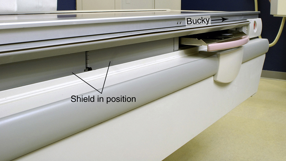
Bucky Slot Shield
The technologist should always ensure the bucky is all the way to the end of the table before beginning a fluoroscopic procedure, which then brings out the metal bucky slot shield to cover the approximately 2 inches (5 cm) of space directly under the tabletop (Fig. 12.59). This shield significantly reduces scatter radiation resulting from the fluoroscopy x-ray tube located under the table. Leakage or scatter rays can escape through this waist-high bucky space if the bucky shield is not completely out on this type of system.
The requirement of the bucky at the end of the table during fluoroscopy not only is important for worker protection but also is necessary to keep the bucky mechanism from the path of the fluoroscopy x-ray tube under the table.
Lead Aprons
Protective aprons of 0.5-mm lead equivalency (Pb/Eq) must always be worn during fluoroscopy. Some technologists and radiologists may also choose to wear lead-equivalent (Pb-Eq) protective eyewear and thyroid shields (Fig. 12.60).
Before the radiologist or technologist places a hand into the fluoroscopy beam, a leaded glove must always be worn, and the beam must be first attenuated by the patient’s body. The use of a compression paddle (see Fig. 12.70) is an even better alternative when compression of the patient’s abdomen is required.
Cardinal Principles of Radiation Protection
One of the best ways to reduce worker dose during fluoroscopy is to apply the following three “cardinal principles of radiation protection.” If these principles are applied correctly, dose to both the fluoroscopist and the technologist can be greatly reduced.
- 1. Time: Reduce the amount of time the fluoroscopy tube is energized. Although most procedures are performed by radiologists and the amount of fluoroscopy time is controlled by them, the technologist should also keep track of fluoroscopy time. If fluoroscopy time becomes excessive, the situation should be discussed with a supervisor. The use of “intermittent fluoroscopy” reduces dose to the patient and workers. With digital fluoroscopy, the “image freeze” function should be used, which allows the last energized image to remain visible on the monitor. Then the fluoroscopy tube is activated only when a new image is required.
- 2. Shielding: Follow all shielding precautions described previously, including correct use of the lead drape shield, the bucky slot shield, and lead gloves.
- 3. Distance: The most effective method of reducing dose during fluoroscopy procedures is to increase the distance between the x-ray tube and the technologist. By applying the inverse square law, technologists can significantly reduce dose to themselves. Doubling the distance between the x-ray tube and the worker can reduce dose by a factor of 4. Technologists should maximize their distance from the x-ray tube when not assisting the radiologist or managing the patient.
See Table 12.4 for a summary of technologist protection devices.
4
TABLE 12.4


Esophagography Procedure
Two common radiographic procedures of the upper gastrointestinal system involving the administration of contrast media are the esophagography and the upper GI series. Each of these procedures is described in detail, beginning with the esophagography
Definition and Purpose
Esophagography is the common radiographic procedure or examination of the pharynx and esophagus in which a radiopaque contrast medium is used. Occasionally, a negative or radiolucent contrast medium may be used.
The purpose of an esophagography is to demonstrate radiographically the form and function of the pharynx and esophagus.
Contraindications
No major contraindications exist for esophagography except possible sensitivity to the contrast media used. The technologist should determine whether the patient has a history of sensitivity to barium sulfate or water-soluble contrast media.
Clinical Indications for Esophagography
Common clinical indications for an esophagography procedure include the following conditions.
- Achalasia (ak″-a-la′-zha), also termed cardiospasm, is a motor disorder of the esophagus in which peristalsis is reduced along the distal two-thirds of the esophagus. Achalasis is evident at the esophagogastric sphincter because of its inability to relax during swallowing. The thoracic esophagus may also lose its normal peristaltic activity and become dilated (megaesophagus). Digital fluoroscopy is most helpful in the diagnosis of achalasia. It occurs equally in males and females and is most common between the ages of 20 and 40 years. 3
- Anatomic anomalies may be congenital or may be caused by disease, such as cancer of the esophagus. Patients who have a stroke often develop impaired swallowing mechanisms. Certain foods and contrast agents are administered during the examination for evaluation of swallowing patterns. A speech pathologist may perform the study to understand better the speech and swallowing patterns of the patient. Digital fluoroscopy is used during these studies.
- Barrett esophagus, or Barrett syndrome, is the replacement of the normal squamous epithelium with columnar-lined epithelium ulcer tissue in the mid-to-lower esophagus (Fig. 12.61). This replacement may produce a stricture in the distal esophagus. In advanced cases, a peptic ulcer may develop in the distal esophagus. The esophagogram may demonstrate subtle tissue changes in the esophagus, but nuclear medicine is the modality of choice for this condition. The patient is injected with technetium-99m pertechnetate to demonstrate the shift in tissue types in the esophagus.
- Carcinoma of the esophagus includes one of the most common malignancies of the esophagus, adenocarcinoma (Fig. 12.62). Advanced symptoms include dysphagia (difficulty in swallowing), localized pain during meals, and bleeding. Other tumors of the esophagus include carcinosarcoma, which often produces a large, irregular polyp, and pseudocarcinoma. An esophagography and endoscopy are performed to detect these tumors. The esophagography may demonstrate atrophic changes in the mucosa caused by invasion of the tumor and stricture. CT may be performed in staging of the tumor and determining whether it has extended beyond the inner layer of mucosa of the esophagus.
- Dysphagia (dis-fa′-je-a) is difficulty swallowing. This difficulty may be due to a congenital or acquired condition, a trapped bolus of food, paralysis of the pharyngeal or esophageal muscles, or inflammation. Narrowing or an enlarged, flaccid appearance of the esophagus may be seen during the esophagography, depending on the cause of the dysphagia. Digital fluoroscopy is the modality of choice.
- Esophageal varices are characterized by dilation of the veins in the wall of the distal esophagus (Fig. 12.63). This condition is often seen with acute liver disease, such as cirrhosis secondary to increased portal hypertension. With restriction in venous flow through the liver, the coronary veins in the distal esophagus become dilated, tortuous, and engorged with blood. In advanced cases, the veins may begin to bleed. Advanced esophageal varices manifest with narrowing of the distal third of the esophagus and a “wormlike” or “cobblestone” appearance caused by enlarged veins during an esophagogram.
- Foreign bodies that patients may ingest include a bolus of food, metallic objects, and other materials that lodge in the esophagus (Fig. 12.64). Locations and dimensions may be determined during an esophagography. Radiolucent foreign bodies, such as fish bones, may require the use of additional materials and techniques for detection. Cotton may be shredded and placed in a cup of barium and then swallowed by the patient. The intent of this technique is to cause a tuft of the cotton to be caught by the radiolucent foreign body and show its location under fluoroscopy. Although this technique has been used for decades, most gastroenterologists prefer the use of endoscopy to isolate and remove these foreign bodies.
- Gastroesophageal reflux disease (GERD), or esophageal reflux, is the entry of gastric contents into the esophagus, irritating the lining of the esophagus. Esophageal reflux is reported as heartburn by most patients. This condition may lead to esophagitis demonstrated by an irregular or ulcerative appearance of the mucosa of the esophagus. Although specific causes for GERD or esophageal reflux have not been confirmed, cigarette smoking and excessive intake of aspirin, alcohol, and caffeine increase the incidence of reflux. It is also common in newborns up to 3 months but often resolves on its own. 3
- Specific methods used to demonstrate esophageal reflux during fluoroscopy are discussed later in this chapter. In advanced cases, the distal esophagus demonstrates longitudinal streaks during an esophagography because of changes in the mucosa. Endoscopy is often performed to detect early signs of GERD.
- Zenker diverticulum is characterized by a large outpouching of the esophagus just above the upper esophageal sphincter (Fig. 12.65). It is believed to be caused by weakening of the muscle wall. Because of the size of the diverticulum, the patient may experience dysphagia, aspiration, and regurgitation of food eaten hours earlier. Although medication can reduce the symptoms of Zenker diverticulum, surgery may be required.


See Table 12.5 for a summary of clinical indications for esophagography.

TABLE 12.5
| Condition or Disease | Most Common Radiographic Examination | Possible Radiographic Appearance | Exposure Factor Adjustment a |
|---|---|---|---|
| Achalasia | Esophagography with digital fluoroscopy | Stricture or narrowing of esophagus | None |
| Anatomic anomalies (including foreign bodies) | Esophagography with digital fluoroscopy (functional study) endoscopy employed for foreign bodies | Abnormal peristaltic patterns | None |
| Various radiopaque and radiolucent foreign bodies | None | ||
| Barrett esophagus | Esophagography or NM scan | Stricture or “streaked” appearance of distal esophagus | None |
| Carcinoma | Esophagography MRI, and CT scan | Point of stricture, narrowing, or atrophic changes in mucosa | None |
| Dysphagia | Esophagography with digital fluoroscopy (functional study) | Narrowing or enlargement of esophagus, depending on cause | None |
| Esophageal varices | Esophagography (and endoscopy) | Narrowing and “wormlike” appearance of esophagus | None |
| Zenker diverticulum | Esophagography (and endoscopy) | Enlarged recess or cavity in proximal esophagus | None |

Patient and Room Preparation for Esophagogram
Because the esophagus is empty most of the time, patients need no preparation for an esophagography unless an upper GI series is to follow. When combined with an upper GI, or if the primary interest is the lower esophagus, preparation for the UGI takes precedence.
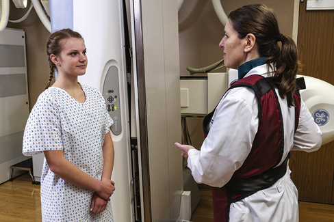
For an esophagography only, all clothing and anything metallic between the mouth and the waist should be removed, and the patient should wear a hospital gown. Before the fluoroscopic procedure is performed, a pertinent history should be taken, and each step of the examination should be carefully explained to the patient (Figs. 12.66).
The first part of an esophagus study involves fluoroscopy with a positive-contrast medium. The examination room should be clean, tidy, and appropriately stocked before the patient is escorted to the room. The appropriate amount and type of contrast medium should be ready. Esophagography generally use both thin and thick barium. Additional items useful in the detection of a radiolucent foreign body are (1) cotton balls soaked in thin barium, (2) barium pills or gelatin capsules filled with BaSO4, and (3) marshmallows. After swallowing any one of these three substances, the patient is asked to swallow an additional thin barium mixture.
Because the esophagography begins with the table in the vertical position, the footboard should be in place and tested for security. Lead aprons, compression paddle, and lead gloves should be provided for the radiologist, in addition to lead aprons for all other personnel in the room. Proper radiation protection methods must be observed at all times during fluoroscopy.
General Procedure
Fluoroscopy
With the room prepared and the patient ready, the patient and the radiologist are introduced, and the patient’s history and the reason for the examination are discussed (Fig, 12.67). The fluoroscopic examination usually begins with a general survey of the patient’s chest, including heart, lungs, diaphragm, and abdomen.
During fluoroscopy, the technologist’s duties generally are to follow the radiologist’s instructions, assist the patient as needed, and expedite the procedure in any manner possible. Because the examination is begun with the patient in the upright or erect position, a cup of thin barium is placed in the patient’s left hand close to the left shoulder. The patient is instructed to follow the radiologist’s instructions concerning how much to drink and when. The radiologist observes the flow of barium with the fluoroscope.
Swallowing (deglutition) of thin barium is observed with the patient in various positions. Similar positions may be used while the patient swallows thick barium. The use of thick barium allows better visualization of mucosal patterns and any lesion within the esophagus. The type of barium mixture to be used is determined by the radiologist.
After upright studies have been completed, horizontal and Trendelenburg positions with thick and thin barium may follow. Fig. 12.68 shows a patient in position for an RAO projection with a cup of thin barium. The pharynx and the cervical esophagus usually are studied fluoroscopically with spot images, whereas the main portion of the esophagus down to the stomach is studied both with fluoroscopy and with postfluoroscopy imaging.


Demonstration of Esophageal Reflux
The diagnosis of possible esophageal reflux or regurgitation of gastric contents may occur during fluoroscopy or an esophagography. One or more of the following procedures may be performed to detect esophageal reflux:
Breathing Exercises
Various breathing exercises are designed to increase both intrathoracic and intra-abdominal pressures. The most common breathing exercise is the Valsalva maneuver. The patient is asked to take a deep breath and, while holding the breath in, to bear down as though trying to move the bowels. This maneuver forces air against the closed glottis. A modified Valsalva maneuver is accomplished as the patient pinches off the nose, closes the mouth, and tries to blow the nose. The cheeks should expand outward as though the patient were blowing up a balloon.
A Mueller maneuver also can be performed as the patient exhales and then tries to inhale against a closed glottis.
With both methods, the increase in intra-abdominal pressure may produce the reflux of ingested barium that would confirm the presence of esophageal reflux. The radiologist carefully observes the esophagogastric junction during these maneuvers.
Water Test
The water test (Fig. 12.69) is done with the patient in the supine position and turned up slightly on the left side. This slight left posterior oblique (LPO) position fills the fundus with barium. The patient is asked to swallow a mouthful of water through a straw. Under fluoroscopy, the radiologist closely observes the esophagogastric junction. A positive water test result is indicated when significant amounts of barium regurgitate into the esophagus from the stomach.
Compression Technique
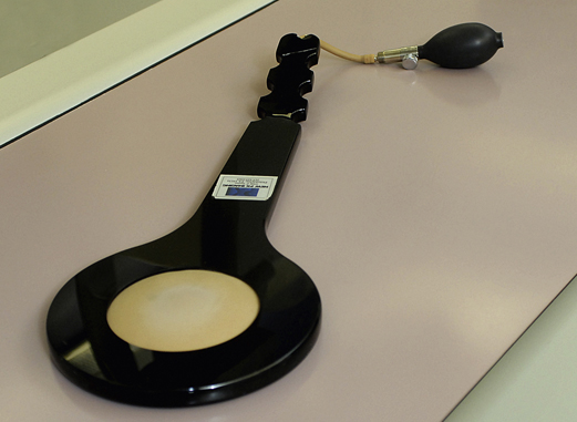
A compression paddle (Fig. 12.70) can be placed under the patient in the prone position and inflated as needed to provide pressure to the stomach region. The radiologist can demonstrate the obscure esophagogastric junction during this process to detect possible esophageal reflux.
Toe-Touch Maneuver
The toe-touch maneuver (Fig. 12.71) also is performed to study possible regurgitation into the esophagus from the stomach. Under fluoroscopy, the cardiac orifice is observed as the patient bends over and touches the toes. Esophageal reflux and hiatal hernias sometimes are demonstrated with the toe-touch maneuver.
Although the procedures described above still are performed, most cases of esophageal reflux are confirmed through endoscopy.
Postfluoroscopy Imaging
After the fluoroscopy portion of the esophagography, radiographs of the entire barium-filled esophagus are obtained. Positioning routines and descriptions for postfluoroscopy imaging are described in detail in the positioning section of this chapter.
The need for postfluoroscopy imaging for esophagography has been greatly reduced with the use of digital fluoroscopy.


Upper GI Series Procedure
In addition to the esophagography, the second and very common radiographic procedure for examination of the upper GI system involving contrast media is the upper GI series.
Definition and Purpose
Radiographic examination of the distal esophagus, stomach, and duodenum is called an upper GI or UGI.
The purposes of the upper GI are to study radiographically the form and function of the distal esophagus, stomach, and duodenum and to detect abnormal anatomic and functional conditions.
Contraindications
Contraindications to upper GI examinations apply primarily to the type of contrast media used. If the patient has a history of bowel perforation, laceration, or rupture of the viscus, the use of barium sulfate may be contraindicated. An oral, water-soluble, iodinated contrast medium may be used in place of barium sulfate.
Clinical Indications for Upper GI Series
Common clinical indications for an upper GI series include the following conditions.
- Bezoar describes a mass of undigested material that becomes trapped in the stomach. This mass usually is made up of hair, certain vegetable fibers, or wood products. The material builds up over time and may form an obstruction in the stomach.
- Specific terms for bezoars include trichobezoar, made up of ingested hair, and phytobezoar, which is ingested vegetable fiber or seeds. 5 Some patients are unable to break down or process certain vegetable fibers or seeds.
- The upper GI demonstrates the bezoar. Radiographic appearances include a mass defined as a filling defect within the stomach. The bezoar retains a light coating of barium even after the stomach has emptied most of the barium (Fig. 12.72).
- Diverticula are pouchlike herniations of a portion of the mucosal wall. They can occur in the stomach or small intestine. Gastric diverticula are generally about ½ inch (1 to 2 cm) but may be as large as 3 inches (8 cm) in diameter. Of gastric diverticula, 70% to 90% arise in the posterior aspect of the fundus. Consequently, the lateral position taken during an upper GI study may be the only projection that demonstrates gastric diverticula. Most gastric diverticula are asymptomatic and are discovered accidentally.
- Although benign, diverticula can lead to perforation if untreated. 5 Other complications include inflammation and ulceration at the site of neoplasm formation. A double-contrast upper GI is recommended to diagnose any tumors or diverticula. An air-filled, barium-lined diverticulum of the duodenal bulb is shown in Fig. 12.73.
- Emesis (em′-e-sis) is the act of vomiting. Blood in vomit is called hematemesis and may indicate that other forms of pathologic processes are present in the gastrointestinal tract.
- Gastric carcinomas account for more than 70% of all stomach neoplasms, and 95% of them are adenocarcinomas. 3 Radiographic signs include a large, irregular filling defect within the stomach, marked or nodular edges of the stomach lining, rigidity of the stomach, and associated ulceration of the mucosa.
- The double-contrast upper GI remains the gold standard for the detection of gastric carcinoma. CT or endoscopy may be performed to determine the degree of invasion of the tumor into tissues surrounding the stomach.
- Gastritis is an inflammation of the lining or mucosa of the stomach (Fig. 12.74). Gastritis may develop in response to various physiologic and environmental conditions. Acute gastritis manifests with severe symptoms of pain and discomfort. Chronic gastritis is an intermittent condition that may be brought on by changes in diet, stress, or other factors.
- Gastritis is best demonstrated with a double-contrast upper GI. The fine coating of barium demonstrates subtle changes to the mucosal lining. Specific radiographic appearances may include, but are not restricted to, absence of rugae, a thin gastric wall, and “speckled” appearance of the mucosa. Endoscopy also may be performed to inspect the mucosa visually for signs of gastritis.
- Hiatal hernia is a condition in which a portion of the stomach herniates through the diaphragmatic opening. The herniation may be slight, but in severe cases, most of the stomach is found within the thoracic cavity above the diaphragm.
- Hiatal hernia may be due to a congenitally short esophagus or weakening of the muscle that surrounds the diaphragmatic opening, allowing passage of the esophagus. 5 These hernias are common in 50% of the U.S. population over the age of 50 years. 3 This form of hiatal hernia may occur in both pediatric and adult patients. An adult moderate-size hiatal hernia is shown in Fig. 12.75, in which a portion of the stomach containing air and barium is seen above the diaphragm.
- Sliding hiatal hernia is a second type of hiatal hernia that is caused by weakening of a small muscle (esophageal sphincter) located between the terminal esophagus and the diaphragm. The purposes of the esophageal sphincter are to keep the cardiac portion of the stomach below the diaphragm and to produce a high-pressure zone to prevent esophageal reflux. As a result of aging or other factors, this sphincter may weaken and permit a portion of the stomach to herniate through the esophageal hiatus. Because the degree of herniation may vary from time to time, it is termed a sliding hiatal hernia. The condition is frequently present at birth, but symptoms of difficulty in swallowing usually do not begin until young adulthood.


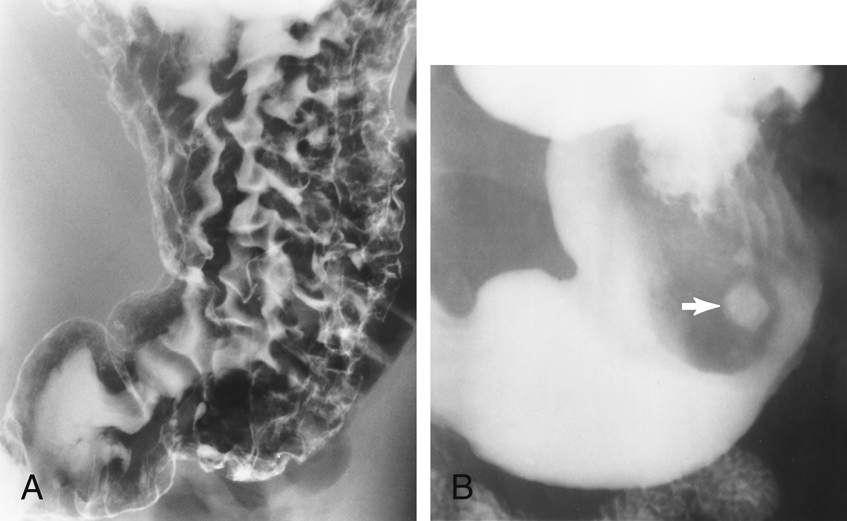
NOTE:A sliding hiatal hernia may produce a radiographic sign termed Schatzki ring, which is a ring of mucosal tissue (which lines the distal esophagus) that protrudes into the lumen of the esophagus
3,5
(Fig. 12.76).
- Hypertrophic pyloric stenosis (HPS) is the most common type of gastric obstruction in infants. It is caused by hypertrophy of the antral muscle at the orifice of the pylorus. Hypertrophy of this muscle produces an obstruction at the pylorus. Symptoms of HPS include projectile vomiting after feedings, acute pain, and possible distention of the abdomen. HPS can be diagnosed during an upper GI. HPS often manifests as distention of the stomach with a small channel (if any at all) of barium passing through the pylorus into the duodenum. Sonography has become the modality of choice in diagnosing HPS. Sonography can measure the diameter and length of the antral muscle to determine whether it is larger (hypertrophic) than normal. It is reported that a muscle thickness greater than 4 mm is a positive sign of HPS. 6 In addition, sonography does not require radiation exposure to the infant or use of contrast media.
- Ulcers are erosions of the stomach or duodenal mucosa that are caused by various physiologic or environmental conditions, such as excessive gastric secretions, stress, diet, and smoking. Some more recent studies suggest that ulcers may be caused by bacteria and can be treated with antibiotics. If untreated, an ulcer may lead to perforation of the stomach or duodenum.
- During an upper GI study, the ulcer appears as a punctate barium collection that may appear to be surrounded by a lucent halo. A small peptic ulcer filled with barium is seen in Fig. 12.77. A double-contrast upper GI is recommended for most ulcer studies. It may be preceded or followed by endoscopy of the upper gastrointestinal tract. Types of ulcers include the following:
-
- • Duodenal ulcer is a peptic ulcer situated in the duodenum. These ulcers frequently are located in the second or third aspect of the duodenum. Duodenal ulcers are rarely malignant. 6
- • Peptic ulcer describes ulceration of the mucous membrane of the esophagus, stomach, or duodenum, caused by the action of acid gastric juice. The term peptic ulcer can be synonymous with gastric ulcer or duodenal ulcer. Peptic ulcer disease often is preceded by gastritis and is secondary to hyperacidity.
- • Gastric ulcer is an ulcer of the gastric mucosa.
- • Perforating ulcer is an ulcer that involves the entire thickness of the wall of the stomach or intestine, creating an opening on both surfaces. Only 5% of all ulcers lead to perforation. 6 If an ulcer becomes perforated, it creates an opening between the intestine and the peritoneal cavity. Radiographic signs include the presence of free air under the diaphragm, as seen with an erect abdomen radiograph. If untreated, this type of ulcer may lead to peritonitis and eventual death.


See Table 12.6 for a summary of clinical indications for the upper GI series.

TABLE 12.6
| Condition or Disease | Most Common Radiographic Examination | Possible Radiographic Appearance | Exposure Factor Adjustment a |
|---|---|---|---|
|
Bezoar
Phytobezoar
Trichobezoar
|
Upper GI or endoscopy | Filling defect or ill-defined mass within stomach | None |
| Diverticula | Double-contrast upper GI | Outpouching of mucosal wall | None |
| Gastric carcinoma | Double-contrast upper GI | Irregular filling defect within stomach | None |
| Gastritis | Double-contrast upper GI | Absence of rugae, thin gastric wall, and “speckled” appearance of mucosa with acute cases of gastritis | None |
| Hiatal hernia (sliding hiatal hernia) | Single-contrast or double-contrast upper GI | Gastric bubble or protruding aspect of stomach above diaphragm or Schatzki ring | None |
| Hypertrophic pyloric stenosis | Upper GI or sonography | Distention of stomach owing to obstruction of pylorus | None |
| Ulcer | Double-contrast upper GI | Punctate collection of barium and “halo” sign | None |

Patient Preparation for Upper GI Series
The goal of patient preparation for an upper GI series is for the patient to arrive in the radiology department with a completely empty stomach. For an examination scheduled during the morning hours, the patient should be NPO from midnight until the time of the examination. Food and fluids should be withheld for at least 8 hours before the examination. The patient also is instructed not to smoke cigarettes or chew gum during the NPO period. These activities tend to increase gastric secretions and salivation, which prevents proper coating of barium to the gastric mucosa.
The upper GI series is often a time-consuming procedure, so the patient should be forewarned about the time the examination may take when the appointment is made. This is especially true if the UGI is to be followed by a small bowel series. The importance of an empty stomach also should be stressed when the appointment is made so that the patient arrives properly prepared both physically and psychologically.
Pregnancy Precautions
If the patient is female, a menstrual history must be obtained. Irradiation of an early pregnancy is one of the most hazardous situations in diagnostic radiography.
Radiographic examinations such as the upper GI series that include the pelvis and the uterus in the primary beam, in addition to fluoroscopy, should be done on pregnant women only when absolutely necessary.
In general, abdominal radiographs of a known pregnancy should be delayed at least until the third trimester or, if the patient’s condition allows (as determined by the physician), until after the pregnancy. This waiting period is especially important when fluoroscopy, which greatly increases patient exposure, is involved.
Room Preparation and Fluoroscopy Procedure
Room setup for a UGI series is very similar to that for an esophagogram. The thin barium sulfate mixture is the typical contrast medium of choice for an upper GI series. Occasionally, thick barium may be used in addition to some type of gas-forming preparation. Rarely, water-soluble contrast media are used in preference to the barium sulfate mixture.
The fluoroscopy table is raised to the vertical position, although with some very ill patients, the examination must be started with the table horizontal. Therefore, the footboard should be placed at the end of the table. The room should be clean and tidy, and the control panel should be set up for fluoroscopy. If conventional fluoroscopy is being used, the spot film mechanism should be properly loaded and in working condition. All image receptors for the entire examination should be set aside for easy access. Lead aprons, lead gloves, and the compression paddle should be available for radiologist as well as lead aprons for all other personnel in the room.
Before introduction of the patient and the radiologist, the patient’s history must be obtained, and the examination procedure must be carefully explained to the patient.
General duties during fluoroscopy for an upper GI series are similar to those for an esophagogram. The technologist should follow the radiologist’s instructions, assist the patient as needed, and expedite the procedure in any manner possible.
The fluoroscopic routine followed by fluoroscopists varies greatly but usually begins with the patient in the upright position (Fig. 12.78). A wide variety of table movements, patient positions, and special maneuvers follow until the fluoroscopy portion of the procedure is complete.

Patient and Table Movements
Various patient positions combined with table movements are used during the fluoroscopic procedure (Fig. 12.79). The technologist must help the patient with the barium cup, provide a pillow when the patient is lying down, and keep the patient adequately covered at all times. The barium cup should be held by the patient in the left hand near the left shoulder whenever the patient is upright. The cup must be taken from the patient when the table is tilted up or down.
Part of the technologist’s responsibility is to watch the patient’s hands and fingers during table movements. Sometimes, holding onto the edge of the table can result in pinched fingers. The radiologist is occupied by watching the fluoroscopy screen or the monitor during these moves and may not be able to see the patient’s hands.
The RAO position, illustrated in Fig. 12.80, allows barium to migrate toward the pyloric portion or distal stomach, whereas any air in the stomach shifts toward the fundus.
Postfluoroscopy Routines
After fluoroscopy, routine positions or projections may be obtained to document further any tentative diagnosis concluded fluoroscopically. These radiographs, such as the RAO shown in Fig. 12.80, must be obtained immediately after fluoroscopy, before too much of the barium has passed into the jejunum.
With digital fluoroscopy, routine postfluoroscopy radiographs may not be requested by the radiologist, as described earlier in this chapter.
Special Patient Considerations
Pediatric Applications
Refer to Chapter 16 for further details.
Pediatric Patient Preparation for Upper GI
The following guidelines are suggested, but department protocol should be followed:
Barium Preparation
Dilution of the barium may be required if the child will be fed through a bottle. A larger hole in the nipple may be required to ensure a smooth flow of barium. Some suggested barium volume guidelines are listed next, but specific department protocol should be followed.
Room Preparation
Most upper GI series for pediatric patients are performed with the table in the horizontal position. Protective aprons must be provided for all persons in the fluoroscopy room (Fig. 12.81). Individuals who feed or restrain the child during fluoroscopy should wear protective gloves and should be instructed not to stand at the head or foot of the table, where radiation exposure is greatest. Pulsed, grid-controlled fluoroscopy should be used to reduce doses for all patients, especially children.
Geriatric Applications
The risk of dehydration during GI studies is a concern for geriatric patients. These patients may require additional attention and monitoring with the normal patient preparation of withholding fluids and ingesting barium. The use of water-soluble contrast agents such as Gastrografin or MD-Gastroview may increase the risk of dehydration further. Geriatric patients should be scheduled for GI studies early in the morning to permit a return to normal fluid and dietary intake after the procedure.
Geriatric patients may require additional time and assistance while changing positions on the table. Geriatric patients may feel nervous and express fear of falling off the examination table.
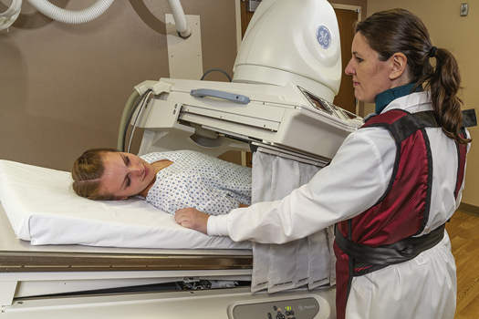
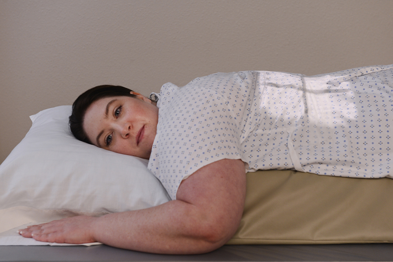

Bariatric Patient Considerations
Preliminary scout and post-contrast introduction images of the stomach and duodenum on bariatric patients may require multiple images be taken to ensure all of the anatomy has been covered. Regardless of the number of images taken to cover the entire stomach and duodenum in the various positions, be sure there is sufficient but not excessive overlap to verify that no anatomic regions are missed.
Very hypersthenic patients may require assistance moving into the necessary positions during the fluoroscopic and postfluoroscopic imaging. Clear instructions are necessary to help the patient successfully move within the confined space under the fluoroscopic tower.
Summary of Positioning Tips for Upper GI Examinations
Clinical History
Obtain a clinical history from the patient, and record the clinical indications for the study. Note any past or recent abdominal surgery, especially surgeries involving the gastrointestinal tract. Surgery or resection of the bowel or stomach may alter its normal position. Pay close attention to the fluoroscopy monitor to detect such differences, which may affect positioning and centering on postfluoroscopy imaging.
Review the patient’s chart to ensure that the correct procedure has been ordered. Also identify specific allergies and other pertinent information.
Body Habitus
Consider the body habitus of the patient. The stomach is high and transverse with a hypersthenic patient but low and vertical with a hyposthenic patient. In a sthenic or average patient the duodenum bulb is near the L2 region. Usually L2 is located 1 to 2 inches (2.5 to 5 cm) above the lower margin of the lateral rib cage. Centering points in this text are designed for the average, sthenic patient.
Fluoroscopy
During fluoroscopy, identify the stomach on the fluoroscopy monitor. Pinpoint surrounding structures to gain clues about the location of the stomach and duodenum. For example, if the body of the stomach is adjacent to the iliac wing, center lower than the average or sthenic patient.
High kVp and Short Exposure Time
A high kVp of 110 to 125 is required to penetrate adequately and increase visibility of barium-filled structures. A kVp less than 100 would not provide visibility of the mucosa of the esophagus, stomach, or duodenum. Short exposure times are needed to control peristaltic motion. With double contrast, reduction of the kVp to 90 to 100 is common to provide higher contrast images without overpenetrating the anatomy (determine departmental kVp preferences). Iodinated, water-soluble contrast studies often require a kVp range of 80 to 90 kVp.
Digital Imaging Considerations
With the use of digital fluoroscopy, postfluoroscopy projections are taken less frequently during esophagography and upper GI procedures. If such projections are requested and digital imaging equipment is used, the following technical considerations should be kept in mind:
- 1. Collimation: To ensure the digital image is recognized correctly by the imaging system and a diagnostic image is produced, close collimation is essential. Because of the proximity of the spine, without accurate collimation the imaging system may rescale the image to display a longer than optimal scale of contrast. This could lead to certain soft tissue structures and pathology being obscured during the image reconstruction process. Careful collimation to the organs of interest minimizes this possibility.
- 2. Accurate centering: Careful analysis of body habitus is crucial during an esophagogram and upper GI procedure. Keep in mind how the position of the stomach varies between a hypersthenic and an asthenic patient. If the stomach is not centered to the IR, the image will not be displayed correctly. It is important to ensure that the central ray, body part, and IR are aligned for correct centering of the anatomy of interest.
- 3. Exposure factors: With digital imaging systems, minimum kVp and mAs must be used to create an acceptable image. Inadequate kVp or mAs produces a “mottled” image; however, the technologist must not increase mAs needlessly because this would increase patient dose. Departments should have established technical charts to ensure that adequate kVp and mAs are used for these procedures. After images have been produced, the exposure index should be verified to determine whether it is within the acceptable range to ensure that sufficient exposure factors were used without needless overexposure of the patient.
Alternative Modalities and Procedures
Computed tomography (CT)
CT is an excellent modality that may be used to demonstrate tumors of the gastrointestinal tract, liver, spleen, and pancreas. With the use of diluted oral contrast media, CT can demonstrate diverticula, hiatal hernia, and bowel perforation.
CT has become the modality of choice for demonstrating trauma and tumors of the gastrointestinal tract and accessory organs.
Magnetic resonance imaging (MRI)
Tumor and vascular disease of the liver and esophageal varices are demonstrated well on MRI with the use of a flow-sensitive, short flip angle pulse sequence. Magnetic resonance cholangiopancreatography (MRCP) is a procedure specific for demonstration of the hepatobiliary and pancreatic systems.
Hemochromatosis, or iron overload, may be a genetic condition or may be due to multiple blood transfusions and is well visualized with MRI. This condition leads to deposition of an abnormal amount of iron within the liver parenchyma. Excessive iron deposited in the tissue produces a strong signal on MRI.
Medical Sonography
Intraesophageal sonography for esophageal varices and carcinoma of the esophagus is becoming an alternative to the esophagography. With passage of a small transducer into the esophagus, detailed images of the inner mucosal layer can be acquired. Small varices and polyps of the esophagus and upper stomach can be evaluated. As stated earlier, ultrasound has become an effective diagnostic tool for HPS in infants.
Doppler ultrasound can be used to detect vascular flow to specific accessory organs in the gastrointestinal tract.
Nuclear Medicine (NM)
With the use of specific radionuclides, NM scans demonstrate cirrhosis of the liver, splenic tumors, gastrointestinal bleeding, and gastric emptying studies. Gastric emptying studies are performed to determine the rate of emptying of food from the stomach.
Also, esophageal reflux can be diagnosed by the addition of a radionuclide to a drink, such as milk. With a compression band placed along the upper abdomen, the nuclear medicine camera can measure any return of gastric contents through the esophagogastric junction. NM is also very effective in demonstrating Barrett esophagus.
Routine and Special Projections
The three routine postfluoroscopy projections for esophagography are described in the following positioning section, along with one special oblique position. The five projections for the upper GI series are listed in order of suggested clinical usefulness when postfluoroscopy projections are requested. With the increased use of digital fluoroscopy, these postfluoroscopy projections are not as common as in the past, but technologists should be able to perform them when requested.
Rao Position—Esophagography
Clinical Indications
Technical Factors
Shielding
Shield all radiosensitive tissues outside region of interest.
Patient Position
Position patient recumbent or erect. Recumbent is preferred because of more complete filling of the esophagus (caused by the gravity factor with the erect position).
Part Position

- • Rotate 35° to 40° from a prone position, with the right anterior body against the IR or table (Fig. 12.82).
- • Place right arm down with left arm flexed at elbow and up by the patient’s head, holding cup of barium, with a straw in patient’s mouth.
- • Flex left knee for support.
- • Align midline of thorax in the oblique position to midline of IR or table.
- • Place top of IR about 2 inches (5 cm) above level of shoulders to place center of IR at CR.
CR
Recommended Collimation
Collimate the lateral borders to create two-sided collimation about 5 to 6 inches (12 to 15 cm) wide. L or R marker should be placed within collimation field.
Respiration
Suspend respiration (see NOTES).
NOTE 1:
Thick barium: Two or three spoonfuls of thick barium should be ingested, and the exposure should be made immediately after the last bolus is swallowed. (The patient generally does not breathe immediately after a swallow.)
NOTE 2:
Thin barium: For complete filling of the esophagus with thin barium, the patient may have to drink through a straw, with continuous swallowing and exposure made after three or four swallows without suspending respiration (using as short an exposure time as possible).


Lateral Position—Esophagography
Clinical Indications
Technical Factors

Shielding
Shield all radiosensitive tissues outside region of interest.
Patient Position
Position patient recumbent or erect (recumbent preferred) (Fig. 12.85).
Part Position
CR
Recommended Collimation
Collimate along the lateral borders to create two-sided collimation about 5 to 6 inches (12 to 15 cm) wide. L or R marker should be placed within collimation field.
Respiration
Suspend respiration.
NOTE:See preceding page for barium swallow instructions.
Optional Swimmer’s Lateral Position
This position (Fig. 12.86) allows for better demonstration of the upper esophagus without superimposition of arms and shoulders.
Position hips and shoulders in true lateral position; separate shoulders from esophageal region by placing upside shoulder down and back, with arm behind back. Place downside shoulder and arm up and in front to hold cup of barium.
Evaluation Criteria
Anatomy Demonstrated:
- • Entire esophagus is seen between thoracic spine and heart (Fig. 12.87).
Position:
Exposure:

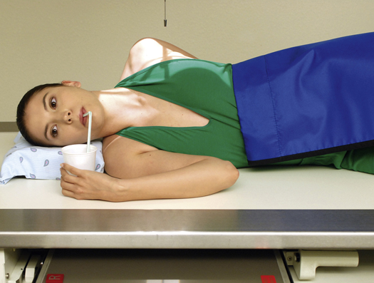

AP (Pa) Projection —Esophagography
Clinical Indications
This projection may not be as diagnostic as the RAO or lateral position.
Technical Factors

Shielding
Shield all radiosensitive tissues outside region of interest.
Patient Position
Position patient recumbent or erect (recumbent preferred) (Fig. 12.88).
Part Position
CR
Recommended Collimation
Use tight side collimation to result in a collimation field that is about 5 to 6 inches (12 to 15 cm) wide. L or R marker should be placed within collimation field.
Respiration
Suspend respiration and expose on expiration.
Alternative PA
This image also can be taken as a PA projection with similar positioning, centering, and CR locations.
NOTES:Two or three spoonfuls of thick barium should be ingested, and the exposure should be made immediately after the last bolus is swallowed. (Patient generally does not breathe immediately after a swallow.)
For complete filling of the esophagus with thin barium, the patient may have to drink through a straw, with continuous swallowing and exposure made after three or four swallows without suspending respiration.
Evaluation Criteria
Anatomy Demonstrated:
- • Entire esophagus is filled with barium (Fig. 12.89).
Position:
Exposure:


Lao Position—Esophagography
Clinical Indications
Technical Factors

Shielding
Shield all radiosensitive tissues outside the region of interest.
Patient Position
Position patient recumbent or erect (recumbent preferred) (Fig. 12.90).
Part Position
- • Rotate 35° to 40° from a PA, with the left anterior body against IR or table.
- • Place left arm down by patient’s side, with right arm flexed at elbow and up by patient’s head.
- • Flex right knee for support.
- • Place top of IR about 2 inches (5 cm) above level of shoulders, to place CR at center of IR.
CR
Recommended Collimation
Collimate lateral borders to create two-sided collimation about 5 to 6 inches (12 to 15 cm) wide. L or R marker should be placed within collimation field.
Respiration
Suspend respiration and expose on expiration.
NOTE 1:
Thick barium: Two or three spoonfuls of thick barium should be ingested, and the exposure should be made immediately after the last bolus is swallowed. (Patient generally does not breathe immediately after a swallow.)
NOTE 2:
Thin barium: For complete filling of the esophagus with thin barium, the patient may have to drink through a straw, with continuous swallowing and exposure made after three or four swallows without suspending respiration (using as short an exposure time as possible).

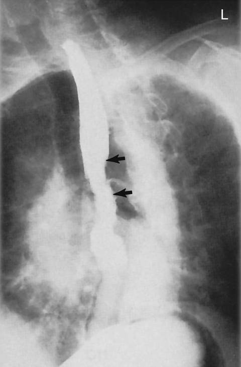
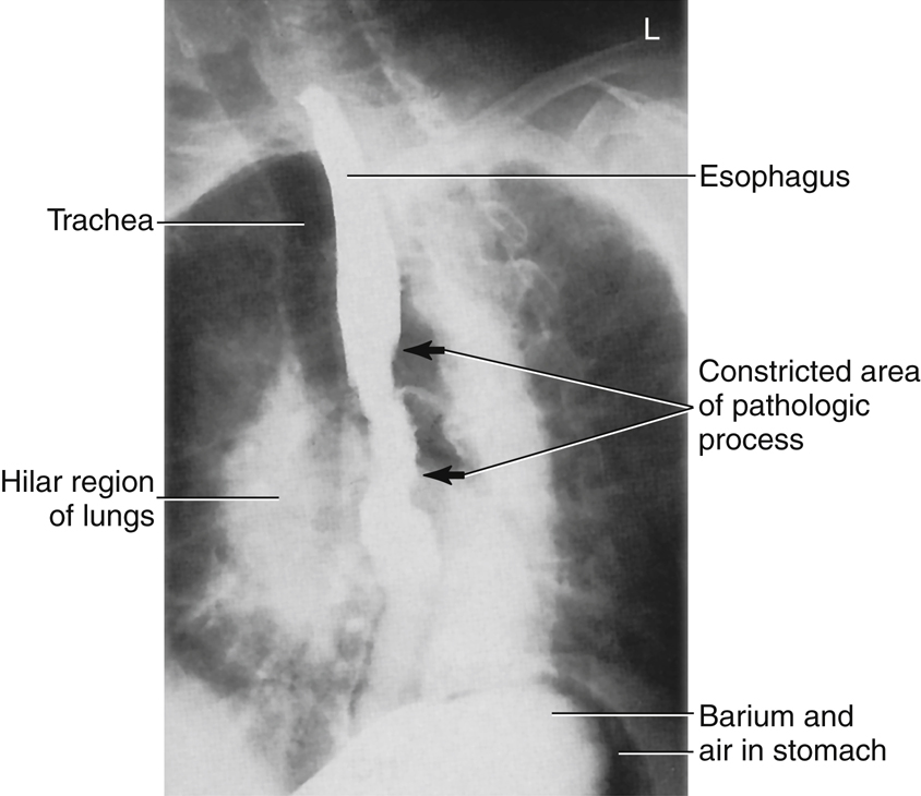
Rao Position—Upper GI Series
Clinical Indications
Technical Factors

Shielding
Shield all radiosensitive tissues outside region of interest.
Patient Position
Position patient recumbent, with body partially rotated into an RAO position; provide a support for patient’s head and upper torso (Fig. 12.93).
Part Position
- • From a prone position, rotate 40° to 70°, with right anterior body against IR or table (more rotation is often required for hypersthenic patients, and less is required for asthenic patients). Place right arm down and left arm flexed at elbow and up by the patient’s head.
- • Flex left knee for support.
CR
- • Direct CR perpendicular to IR
- • Sthenic body type: Center CR and IR to duodenal bulb at level of L1 (1 to 2 inches [2.5 to 5 cm] above lower lateral rib margin), midway between spine and upside lateral border of abdomen, 45° to 55° oblique
- • Asthenic body type: Center about 2 inches (5 cm) below level of L1, 40° oblique
- • Hypersthenic body type: Center about 2 inches (5 cm) above level of L1 and nearer midline, 70° oblique
- • Center IR to CR
Recommended Collimation
Collimate on four sides to outer margins of IR or to area of interest on larger IR. L or R marker should be placed within collimation field.
Respiration
Suspend respiration and expose on expiration.


PA Projection—Upper GI Series
Clinical Indications
Technical Factors

Shielding
Shield all radiosensitive tissues outside region of interest.
Patient Position
Position patient prone, with arms up beside head; provide a support for patient’s head (Fig. 12.96).
Part Position
CR
- • Direct CR perpendicular to IR.
- • Sthenic body type: Center CR and IR to level of pylorus and duodenal bulb at level of L1 (1 to 2 inches [2.5 to 5 cm] above lower lateral rib margin) and about 1 inch (2.5 cm) left of the vertebral column.
- • Asthenic body type: Center about 2 inches (5 cm) below level of L1.
- • Hypersthenic body type: Center about 2 inches (5 cm) above level of L1 and nearer midline.
- • Center IR to CR.
Recommended Collimation
Collimate on four sides to outer margins of IR or to area of interest on a larger IR. L or R marker should be placed within collimation field.
Respiration
Suspend respiration and expose on expiration.
Alternate PA Axial
The position of the high transverse stomach on a hypersthenic patient causes almost an end-on view, with much overlapping of the pyloric region of the stomach and the duodenal bulb with a PA projection (Fig. 12.97). Therefore, a 35° to 45° cephalic angle of the CR separates these areas for better visualization. The greater and lesser curvatures of the stomach also are better visualized in profile.
For infants, a 20° to 25° cephalic CR angle is recommended to open the body and pylorus of stomach.


Right Lateral Position—Upper GI Series
Clinical Indications
Technical Factors

Shielding
Shield all radiosensitive tissues outside region of interest.
Patient Position
Position patient recumbent in a right lateral position (Fig. 12.98). Provide a support for patient’s head. Place arms up near patient’s head and flex knees.
Part Position
CR
- • Direct CR perpendicular to IR
- • Sthenic body type: Center CR and IR to duodenal bulb at level of L1 (level of lower lateral margin of the ribs) and 1 to 1½ inches (2.5 to 4 cm) anterior to midcoronal plane (near midway between anterior border of vertebrae and anterior abdomen)
- • Hypersthenic body type: Center about 2 inches (5 cm) above L1
- • Asthenic body type: Center about 2 inches (5 cm) below L1
Recommended Collimation
Collimate on four sides to outer margins of IR or to area of interest on larger IR. L or R should be placed within collimation field.
Respiration
Suspend respiration and expose on expiration.
NOTE:The stomach generally is located about one vertebra higher in this position than in the PA or oblique position.


Lpo Position—Upper GI Series
Clinical Indications
Technical Factors

Shielding
Shield all radiosensitive tissues outside region of interest.
Patient Position
Position patient recumbent, with the body partially rotated into an LPO position; provide support for patient’s head and upper torso (Fig. 12.101).
Part Position
- • Rotate 30° to 60° from supine position, with left posterior against IR or table (more rotation (up to 60°) is often required for hypersthenic body habitus and less rotation (30°) for asthenic body habitus 7 ).
- • Flex right knee for support.
- • Extend left arm from body and raise right arm high across chest to grasp end of table for support. (Do not pinch fingers when moving bucky.)
- • Center IR at CR (bottom of IR at level of iliac crest).
CR
- • Direct CR perpendicular to IR
- • Sthenic body type: Center CR and IR to level of L1 (about midway between xiphoid tip and lower lateral margin of ribs) and midway between midline of body and left lateral margin of abdomen, 45° oblique
- • Hypersthenic body type: Center about 2 inches (5 cm) above L1, 60° oblique
- • Asthenic body type: Center about 2 inches (5 cm) below L1 and nearer to midline, 30° oblique
Recommended Collimation
Collimate on four sides to outer margins of IR or to area of interest on larger IR.
Respiration
Suspend respiration and expose on expiration.
NOTE:The stomach generally is located higher in this position than in the lateral; therefore, center one vertebra higher than on PA or RAO position.


AP Projection—Upper GI Series
Clinical Indications
Technical Factors

Shielding
Shield all radiosensitive tissues outside region of interest.
Patient Position
Position patient supine, arms at sides; provide a support for patient’s head and knees (Fig. 12.103).
Part Position
CR
- • Center CR perpendicular to IR
- • Sthenic body type: Center CR and IR to level of L1 (about midway between xiphoid tip and lower margin of ribs), midway between midline and left lateral margin of abdomen
- • Hypersthenic body type: Center about 2 inches (5 cm) above L1
- • Asthenic body type: Position CR about 2 inches (5 cm) below and nearer to midline
Recommended Collimation
Collimate on four sides to outer margins of IR or to area of interest if larger IR is used.
Respiration
Suspend respiration and expose on expiration.
Alternative AP: Partial Trendelenburg Position
A partial Trendelenburg (head-down) position may be necessary to fill the fundus on a thin asthenic patient. A full Trendelenburg angulation facilitates the demonstration of hiatal hernia. (Install shoulder brace for patient safety.)


