Chapter 14: Urinary System and Venipuncture
Contributions By Chad Hensley, PhD, RT(R)(MR), Contributors To Past Editions Leslie E. Kendrick, MS, RT(R)(CT)(MR), Jenny A. Kellstrom, MEd, RT(R), and Barry T. Anthony, RT(R)
Radiographic Anatomy
Urinary System
Radiographic examinations of the urinary system are among the common contrast medium procedures performed in radiology departments. The urinary system consists of two kidneys, two ureters (u-re′-ter
1
or yoo-ret′-er
2
), one urinary bladder, and one urethra (u-re′-thrah
1
or yoo-re′-thra
2
) (Fig. 14.1).
NOTE: Determine which of the possible pronunciations of these terms is (are) most common in your region.
The two kidneys and the ureters are organs that lie in the retroperitoneal space. These two bean-shaped organs lie on either side of the vertebral column in the most posterior part of the abdominal cavity. The right kidney is generally slightly lower or more inferior than the left because of the presence of the liver. Superior and medial to each kidney is a suprarenal (adrenal) gland. These important glands of the endocrine system are located in the fatty capsule that surrounds each kidney.
Each kidney is connected to the single urinary bladder by its own ureter. Waste material, in the form of urine, travels from the kidneys to the bladder via the ureters. The saclike urinary bladder serves as a reservoir that stores urine until it can be eliminated from the body via the urethra.
The Latin designation for kidney is ren, and renal is an adjective that is commonly used to refer to the kidney.
Kidneys
The various organs of the urinary system and their relationship to the bony skeleton are shown from the back in Fig. 14.2 and from the left side in Fig. 14.3. The posteriorly placed kidneys lie in the upper posterior abdomen on either side of the vertebral column. The right kidney is positioned posterior to the lower portion of the liver. The left kidney is positioned posterior to the inferior border of the spleen (see Fig. 14.2). The lower rib cage thus forms a protective enclosure for the kidneys.
Ureters
Most of each ureter lies anterior to its respective kidney. The ureters follow the natural curve of the vertebral column. Each ureter initially curves anteriorly, following the lumbar lordotic curvature, and then curves posteriorly on entering the pelvis. After passing into the pelvis, each ureter follows the sacrococcygeal curve before entering the posterolateral aspect of the bladder.
Urethra
The urethra connects the bladder to the exterior. The urethra exits from the body inferior to the symphysis pubis.
The entire urinary system is posterior to or below the peritoneum. The kidneys and ureters are retroperitoneal structures, whereas the bladder and urethra are infraperitoneal structures.


Kidneys
The average adult kidney is fairly small, weighing about 5¼ oz (150 g). The measurements are 4 to 5 inches (10 to 12 cm) long, 2 to 3 inches (5 to 7.5 cm) wide, and 1 inch (2.5 cm) thick. The left kidney is a little longer, but more narrow than the right. Despite its small size, at least one functional kidney is absolutely essential for normal health. Failure of both kidneys, unless corrected, means inevitable death.
Kidney Orientation
The usual orientation of the kidneys in the supine individual is shown in Fig. 14.4. The large muscles on either side of the vertebral column cause the longitudinal plane of the kidneys to form a vertical angle of about 20° with the midsagittal plane. These large muscles include the two psoas (so′-es) major muscles. These muscle masses grow larger as they progress inferiorly from the upper lumbar vertebrae. This gradual enlargement produces the 20° angle, wherein the upper pole of each kidney is closer to the midline than its lower pole (see Fig. 14.4).
These large posterior abdominal muscles also cause the kidneys to rotate backward within the retroperitoneal space. As a result, the medial border of each kidney is more anterior than the lateral border (Fig. 14.5).
The aorta and inferior vena cava are also indicated to show their relationship to the kidneys.
Cross-Sectional View
Transverse cross-sectional views through the level of L2 illustrate the usual amount of backward rotation of the kidneys (Figs. 14.5 and 14.6). The normal kidney rotation of about 30° is due to the midline location of the vertebral column and the large psoas major muscles on either side. The quadratus lumborum muscles are also shown on each side just posterior to the kidneys. The deep muscles of the back include the group of erector spinae muscles on each side of the spine.
When posterior oblique projections are used during radiographic studies of the urinary system, each kidney in turn is placed parallel to the plane of the image receptor. The body is rotated about 30° in each direction to place one kidney, and then the other, parallel to the image receptor (IR) plane. A 30° left posterior oblique (LPO) positions the right kidney parallel to the IR, and a 30° right posterior oblique (RPO) positions the left kidney parallel.
Each kidney is surrounded by a mass of fatty tissue termed the
adipose capsule,
or perirenal fat. The presence of these fatty capsules around the kidneys permits radiographic visualization of the kidneys on plain abdominal radiographs. A sufficient density difference between fat and muscle allows visualization of the outline of each kidney on most technically satisfactory abdominal radiographs.
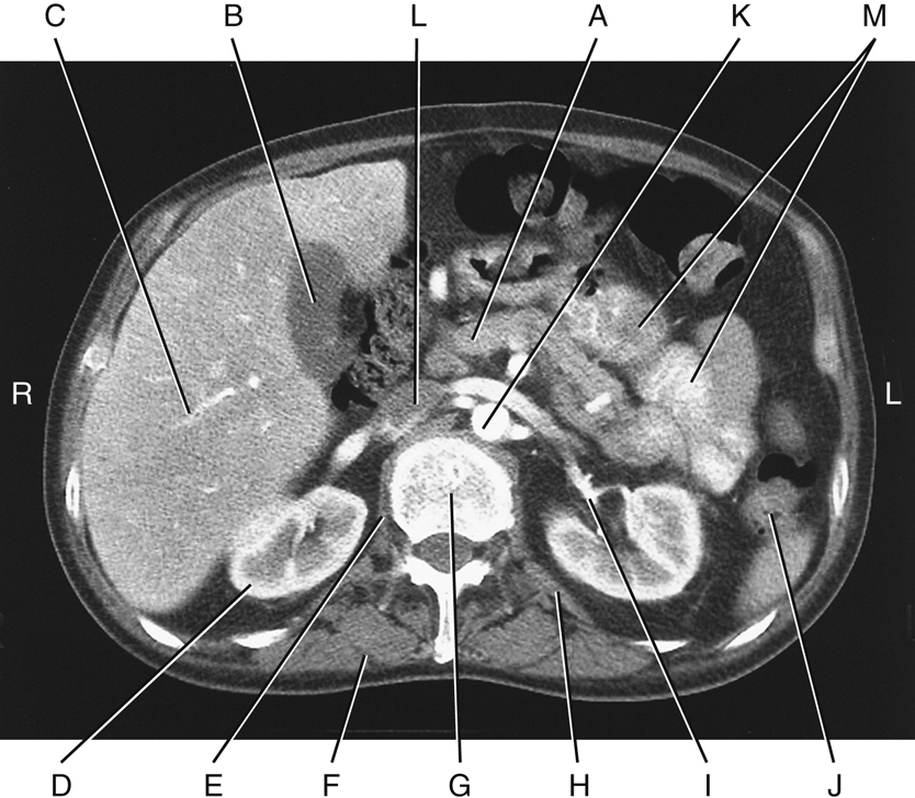
CT Axial Section
Fig. 14.6 represents a computed tomography (CT) axial section through the level of the midkidneys at L2. This section demonstrates the anatomic relationships of the kidneys to adjoining organs and structures. The anatomy that should be recognizable is as follows:
- A. Pancreas
- B. Gallbladder
- C. Right lobe of the liver
- D. Right kidney
- E. Right crus of the diaphragm
- F. Erector spinae muscles
- G. L2 vertebra
- H. Quadratus lumborum muscle
- I. Renal pelvis—proximal ureter of left kidney
- J. Descending colon
- K. Abdominal aorta
- L. Inferior vena cava (IVC)
- M. Small intestine (jejunum)


Normal Kidney Location
Most abdominal radiographs are performed on expiration with the patient supine. The combined effect of expiration and a supine position allows the kidneys to lie slightly higher in the abdominal cavity. Under these conditions, the kidneys normally lie about halfway between the xiphoid process and the iliac crest. The left kidney normally lies about 1 cm more superior than the right one. The top of the left kidney is usually at the level of the T11–T12 interspace. The bottom of the right kidney is most often level with the superior endplate of L3 (Fig. 14.7).
Kidney Movement
Because the kidneys are only loosely attached within their fatty capsule, they tend to move up and down with movements of the diaphragm and position changes. When one inhales deeply, the kidneys normally drop about 1 inch (2.5 cm). When one stands upright, the kidneys normally drop about one lumbar vertebra, or 2 inches (5 cm). If the kidneys drop farther than this, a condition termed
nephroptosis
(nef″-rop-to′-sis) is said to exist. With some very thin and older patients in particular, the kidneys may drop dramatically and end up within the pelvis, which may create problems caused by “kinking” or twisting of the ureters.
Functions of Urinary System
The primary function of the urinary system is the production of urine and its elimination from the body. During urine production, the kidneys perform the following functions:
Nitrogenous waste products such as urea and creatinine are formed during the normal metabolism of proteins. Buildup of these nitrogenous wastes in the blood results in the clinical condition termed
uremia
and may indicate renal dysfunction.
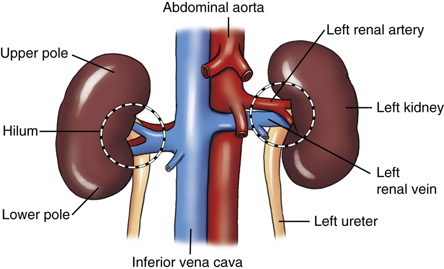
Renal Blood Vessels
Large blood vessels are needed to handle the vast quantities of blood flowing through the kidneys daily. At rest, about 25% of the blood pumped from the heart with each beat passes through the kidneys. Arterial blood is received by the kidneys directly from the abdominal aorta via the left and right renal arteries. Each renal artery branches and rebranches until a vast capillary network is formed within each kidney.
Because most of the blood volume that enters the kidneys is returned to the circulatory system, the renal veins must be large vessels. The renal veins connect directly to the inferior vena cava to return the blood to the right side of the heart. The renal veins are anterior to the renal arteries (Fig. 14.8).
Along the medial border of each kidney is a centrally located, longitudinal fissure termed the
hilum
(hi′-lum). The hilum serves to transmit the renal artery, renal vein, lymphatics, nerves, and ureter. Each kidney is generally divided into an upper part and a lower part, called the upper pole and the lower pole, respectively.
Urine Production
The average water intake for humans during a 24-hour period is approximately 2.5 L (2500 mL). This water comes from ingested liquids, foods, and from the end products of metabolism. This 2.5 L of water eventually ends up in the bloodstream. Vast quantities of blood are filtered through the kidneys. At rest, more than 1 L of blood flows through the kidneys every 60 seconds, which results in removal of about 180 L of filtrate from the blood every 24 hours. More than 99% of this filtrate volume is reabsorbed by the kidneys and returned to the bloodstream. During the reabsorption process, the blood pH and quantities of various electrolytes, such as sodium, potassium, and chloride, are regulated (Fig. 14.9).
From the large amount of blood that flows through the kidneys each day, an average of approximately 1.5 L (1500 mL) of urine is formed. This amount varies greatly, depending on fluid intake, amount of perspiration, and other factors.


Macroscopic Structure
The macroscopic internal structure of the kidney is shown in Fig. 14.10. The outer covering of the kidney is termed the renal (fibrous) capsule.
Directly under the renal capsule, surrounding each kidney, is the cortex. This forms the peripheral, or outer, portion of the kidney. Under the cortex is the internal structure termed the
medulla,
which is composed of 8 to 18 conical masses termed renal pyramids.
The cortex periodically dips between the pyramids to form the renal columns, which extend to the renal sinus.
The renal pyramids are primarily a collection of tubules that converge at an opening called the renal papilla (apex). This renal papilla drains into the minor calyx (kal′-lis or ka′-liks
2
). Calyces appear as hollowed flattened tubes. From 4 to 13 minor calyces unite to form two to three major calyces. The major calyces unite to form the renal pelvis, which appears in the shape of a larger flattened funnel. Each expanded renal pelvis narrows to continue as the ureter. Thus, urine formed in the microscopic or nephron portion of the kidney finally reaches the ureter by passing through the various collecting tubules, a minor calyx, and a major calyx, and finally to the renal pelvis.
The general term
renal parenchyma
(par-eng′-ki-mah) is used to describe the total functional portions of the kidneys, such as those visualized during an early phase of an intravenous (IV) urographic procedure.
The structural and functional unit of the kidney is the microscopic nephron. Approximately 1 million nephrons exist within each kidney. One such nephron is shown in Fig. 14.11, a greatly magnified but very small cutaway section of the kidney. A more detailed view of a single nephron and its collecting ducts is shown in Fig. 14.12. Small arteries in the renal cortex form tiny capillary tufts, termed
glomeruli
(glo-mer′-u-li). Blood initially is filtered through the many glomeruli.
Afferent arterioles supply blood to the glomeruli. Efferent arterioles take blood away to a secondary capillary network in close relation to the straight and convoluted tubules. Each glomerulus is surrounded by a glomerular capsule (Bowman capsule), which is the proximal portion of each nephron collecting filtrate. (The glomerulus is also part of the nephron, which is made up of the glomerulus and the long tubules.) The glomerular filtrate travels from the glomerular capsule to a proximal convoluted tubule, to the descending and ascending limbs of the loop of Henle
a
(Hen′-le), to a distal convoluted tubule, to a collecting tubule and, finally, into a minor calyx. The filtrate is termed urine by the time it reaches the minor calyx. Between the Bowman capsule and the minor calyces, more than 99% of the filtrate is reabsorbed into the kidney’s venous system.
Microscopically, the glomeruli, glomerular capsules, and proximal and distal convoluted tubules of the many nephrons are located within the cortex of the kidney. The loop of Henle and the collecting tubules are located primarily within the medulla. The renal pyramids within the medulla are primarily a collection of tubules. The major calyces unite to form the renal pelvises.


Ureters
The ureters transport urine from the kidneys to the urinary bladder. Slow peristaltic waves and gravity force urine down the ureters into the bladder, as demonstrated in Fig. 14.13. This is a radiographic image taken 10 minutes after injection of contrast medium into the bloodstream. It was performed as part of an IV urographic procedure.
The renal pelvis leaves each kidney at the hilum to become the ureter. The ureters vary in length from about 11 to 13 inches (28 to 34 cm), with the right one being slightly shorter than the left.
As the ureters pass inferiorly, they lie on the anterior surface of each psoas major muscle (Fig. 14.14). Continuing to follow the curvature of the vertebral column, the ureters eventually enter the posterolateral portion of each side of the urinary bladder.
Ureter Size and Points of Constriction
The ureters vary in diameter from 1 mm to almost 1 cm. Normally, three constricted points exist along the course of each ureter. If a kidney stone attempts to pass from the kidney to the bladder, it may have trouble passing through these three regions (see Fig. 14.14).
The first point is the ureteropelvic (u-re″-ter-o-pel′-vic) (UP) junction, at which the renal pelvis funnels down into the small ureter. This section is best seen on the radiograph in Fig. 14.13.
The second is near the brim of the pelvis, where the iliac blood vessels cross over the ureters (see Fig. 14.14).
The third is where the ureter joins the bladder, termed the ureterovesical (u-re″-ter-o-ves′-i-kal) junction, or UV junction. Most kidney stones that pass down the ureter tend to hang up at the third site, the UV junction. Once the stone passes this point and moves into the bladder, it generally has little trouble passing from the bladder through the urethra to the exterior.
Urinary Bladder
The urinary bladder is a musculomembranous sac that serves as a reservoir for urine. The empty bladder is somewhat flattened and assumes the more oval shape seen only when partially or fully distended (Fig. 14.13).
The triangular portion of the bladder along the inner, posterior surface is termed the trigone (tri′-gon). The trigone is the muscular area formed by the entrance of the two ureters from behind and the exit site of the urethra (see Fig. 14.15A). The trigone is firmly attached to the floor of the pelvis. The mucosa of the trigone is smooth, whereas the remaining aspect of the inner mucosa of the bladder has numerous folds termed rugae. As the bladder fills, the top of the bladder expands upward and forward toward the abdominal cavity.
In the male anatomy, the gland that surrounds the proximal urethra is the prostate gland. It is situated inferior to the bladder and measures approximately 1½ inches (3.8 cm) in diameter and 1 inch (2.5 cm) in height. Fig. 14.15B represents a male bladder, although the internal structure of the bladder is similar in both genders. The prostate produces a fluid that improves the motility of sperm during reproduction.


From Drake RL et.al. Gray’s atlas of anatomy, ed 3, Philadelphia, 2021, Elsevier.
Bladder Functions
The bladder functions as a reservoir for urine and, aided by the urethra, expels urine from the body. Normally, some urine is in the bladder at all times, but as the amount reaches 250 mL, the desire to void arises. Retention of urine in the bladder is maintained through the involuntarily controlled internal urethral sphincter (IUS) and the voluntarily controlled external urethral sphincter (EUS). The IUS is located at the junction of the bladder to the urethra (neck of the bladder); the EUS is more distal. In males the EUS is distal to the prostate. The female EUS is more elaborate than males and composed of 3 areas that include: 1) Urethral sphincter 2) Compressor urethrae 3) Urethrovaginalis sphincter (Fig. 14.15A). The act of voiding (urination/micturation) is normally under voluntary control through relaxation of the EUS, and the desire to void may pass if the bladder cannot be emptied right away. The total capacity of the bladder varies from 350 to 500 mL. As the bladder becomes fuller, the desire to void becomes more urgent. If the internal bladder pressure rises too high, involuntary urination occurs. Weakening or damage to the EUS can also lead to involuntary urination called incontinence.
Size and Position of the Bladder
The size, position, and functional status of the bladder depend somewhat on surrounding organs and the amount of urine within the bladder. When the rectum contains fecal matter, the bladder is pushed upward and forward. During pregnancy, as shown in Fig. 14.16, the fetus can exert tremendous downward pressure on the bladder.
NOTE: This drawing is provided only to show the anatomy and location of the urinary bladder in relation to the symphysis pubis and fetus. Remember, no radiographic urinary system examinations or procedures are performed during pregnancy, except in rare cases in which the benefits outweigh the risks, as determined by a physician.
Female Pelvic Organs
The female pelvic organs are shown in the midsagittal section in Fig. 14.17. The urinary bladder lies posterior to and just superior to the upper margin of the symphysis pubis, depending on the amount of bladder distention. The female urethra is a narrow canal, about 1½ inches (4 cm) long, which extends from the internal urethral orifice to the external urethral orifice. The single function of the female urethra is the passage of urine to the exterior.
Female Reproductive Organs
The female reproductive organs include the paired ovaries (female gonads), the uterine (fallopian) tubes, and the vagina (see Fig. 14.17).
A close relationship exists between the urethra and bladder and the uterus and vagina. The urethra is embedded in the anterior wall of the vagina. The spatial relationship of the three external openings becomes important during certain radiographic procedures. The anal opening is most posterior, the urethral opening is most anterior, and the vaginal opening is in between.
Retroperitoneal and Infraperitoneal Organs
The kidneys and ureters are shown to be retroperitoneal organs located posterior to the peritoneal cavity in both males and females. The urinary bladder, urethra, and male reproductive organs are infraperitoneal (inferior to the peritoneal cavity).
As described in Chapter 3, the female uterus, uterine tubes, and ovaries pass into the peritoneal cavity. The male reproductive organs, however, are located totally below the peritoneum and are separated completely from organs within the peritoneal cavity. Thus the lower aspect of the peritoneum is a closed sac in the male but not in the female.
Male Pelvic Organs
The male pelvic organs are shown in the midsagittal section in Fig. 14.18. When the urinary bladder is empty, most of the bladder lies directly posterior to the superior margin of the symphysis pubis. As the bladder distends, as it would during cystography, the radiographic study of the bladder, more and more of the bladder lies above the level of the symphysis pubis.
Male Reproductive Organs
The male reproductive organs include the testes (male gonads), seminal vesicles and related ducts, ejaculatory ducts and ductus deferens (vas deferens), penis, and scrotum, which contains the testes. The relative location of these organs is shown in Fig. 14.18.
The male urethra extends from the internal urethral orifice to the external urethral orifice at the end of the penis. The urethra extends through the prostate gland and the entire length of the penis. The male urethra averages 6½ to 7½ inches (17.5 to 20 cm) in length and has two functions—to eliminate urine stored in the bladder and to serve as a passageway for semen.


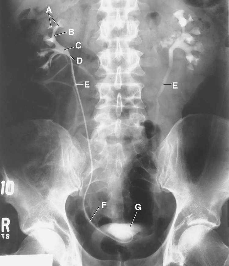
Anatomy Review
Retrograde Pyelogram
Identify the following anatomic structures as labeled on this retrograde pyelogram (Fig. 14.19) in which contrast medium is being injected through a catheter inserted (retrograde) through the urethra, bladder, and ureter to the level of the renal pelvis:
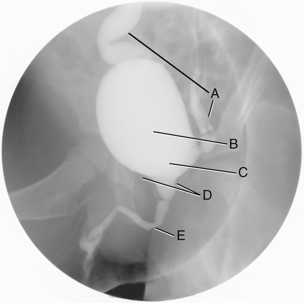
Voiding Cystourethrogram
Identify the following anatomic structures labeled on this radiograph of the urinary bladder and urethra (Fig. 14.20), taken as a young male patient is voiding the contrast medium (patient with vesicoureteral reflux; see p. 547 for explanation):
Computed Tomography Axial Section
Anatomic structures of the abdomen are seen in a sectional view of an axial CT image (Fig. 14.21). Identifying the following abdominal organs and structures provides a good review of all abdominal anatomic structures and their relative relationships to one another:

Venipuncture
Introduction
Venipuncture is defined as the percutaneous puncture of a vein for withdrawal of blood or injection of a solution such as contrast medium for urographic procedures. In the past, venipuncture for urography was performed by physicians, laboratory staff, or nursing personnel. However, venipuncture is part of the scope of practice for the diagnostic imaging professional. Although it is within the technologist’s scope of practice, it is important to be aware of local laws and institutional policies that may require an additional certification in venipuncture.
Preparation for Administration of Contrast Agents
Before contrast medium is withdrawn from any vial or bottle, confirmation of the correct contents of the container, route of administration, amount to be administered, and expiration date is imperative (Fig. 14.22).
Water-soluble, iodinated contrast medium is used for radiographic examinations of the urinary system. This type of contrast medium can be administered by bolus injection or drip infusion.
Bolus Injection
A bolus injection is one in which the entire dose of contrast medium is injected into the venous system at one time (Fig. 14.23). This method of administration is typically used for maximum contrast enhancement. Hand injection or the use of a power injector are both acceptable methods.
The rate of bolus injection is controlled by the following:
Drip Infusion
Drip infusion is a method whereby contrast medium is introduced into the venous system via connective tubing attached to the IV site. A specified amount of contrast medium is introduced over a specified period. This method is used most frequently when the drip infusion catheter is already in place for repeated or continuous infusions.
The contrast medium is contained in an IV solution bag or bottle that is inverted and connected to the tubing (Fig. 14.24). The rate of infusion, which may be gradual or rapid, depending on the needs of the study, is controlled by a clamp device located below the drip chamber on the IV tubing.
Equipment and Supplies
In preparation for this procedure, the technologist must gather all necessary supplies (Fig. 14.25). These supplies should include access to an emergency cart stocked with epinephrine or Benadryl® for emergency injection in the event of an adverse contrast reaction.
The following is a list of supplies needed for performance of venipuncture:
-
- • Sharps container
- • Tourniquets
- • Alcohol wipe
- • Various sizes of butterfly and over-the-needle catheters
- • Disposable or prefilled syringes
- • IV infusion tubing
- • Arm board
- • Cotton balls or 2 × 2-inch (5 × 5-cm) gauze
- • Tape or securing device (e.g., Tegaderm)
- • Gloves (latex-free recommended)
- • Water-soluble, iodinated contrast medium


Patient Preparation
During introductions, identification of the patient, and explanation of the procedure, the mental and emotional status of the patient must be assessed. This assessment may confirm the patient is more comfortable lying down, especially if syncope (temporary loss of consciousness) is a concern.
When assessing a child, the technologist must determine the child’s ability to cooperate during the procedure. If the technologist believes the child may become combative or move suddenly during needle insertion, the guardian or other personnel should be asked to help keep the child calm and immobilize the limb. However, attempts to gain the cooperation of the child through proper therapeutic communication are always preferable. The technologist should not mislead a child in terms of the discomforts of the procedure, but should instead be truthful. The technologist should be open to questions and recognize a child’s concerns.
Signing Informed Consent Form
Venipuncture is an invasive procedure that carries risks for complications, especially when contrast medium is injected. Before beginning the procedure, the technologist must ensure the patient is fully aware of these potential risks and has signed an informed consent form. If a child is undergoing venipuncture, the procedure should be explained to the child and guardian. The guardian must sign the informed consent form.
Selection of Vein
For most IV urograms, veins found within the antecubital fossa are ideal. Veins in this region are generally large, easy to access, and typically sufficiently durable to withstand a bolus injection of contrast medium without extravasation (leaking of the contrast medium from a blood vessel into the surrounding tissues).
Veins found within the antecubital fossa commonly used during venipuncture include the median cubital, cephalic, and basilic veins. Because these typically are easily accessible veins, they may become overused from frequent phlebotomy and IV access. Other access sites might have to be investigated if the antecubital fossa veins are damaged or inaccessible. Other common IV access sites include the cephalic vein of the lateral wrist and veins on the posterior hand or lower forearm, such as the cephalic or basilic veins (Fig. 14.26).
The technologist should avoid veins that are sclerotic (hardened), tortuous (twisted), rolling, or overused. Areas of vein bifurcation or veins that lie directly over an artery should not be used. Do not inject directly into a shunt, central line, or vascular catheter unless it has been manufactured for contrast injections or under the direction of a physician.
Ensure Vessel is a Vein and not an Artery
When selecting an injection site, ensure the vessel is not an artery. The vessel should not be pulsatile and most likely will be close to the skin’s surface.
Type and Size of Needle
For bolus injections of 50 to 100 mL of contrast medium into adults, an 18- to 22-gauge needle is generally used. Some technologists prefer the butterfly needle and claim this type of needle provides greater control during venipuncture because of the two side flaps (Fig. 14.27). The size of the needle is determined by the size of the vein. The length of the needle may vary between 1 and 1 ½ inches (2.5 to 3.75 cm). For pediatric patients, a smaller 23- to 25-gauge needle is often used. The technologist may choose to use an over-the-needle catheter instead of the butterfly.


NOTE: It is recommended that IV access be maintained until the imaging procedure is completed in the event that treatment for an adverse contrast reaction becomes necessary.
Venipuncture Procedure
Step 1: Wash Hands and Put On Gloves (Figs. 14.28 and 14.29)
After making introductions, checking the patient’s ID, explaining the procedure, and obtaining a signature for the consent form, the technologist proceeds with the following:
Step 2: Apply Tourniquet, Select Site, and Cleanse the Site (Figs. 14.30 to 14.32)
- A. Ensure patient comfort by having the person sit or lie down. Support the arm of interest by using a hard surface such as a table. Adjust the height of the arm to match the appropriate working level of the technologist. Select the injection site by using the technologist’s finger of the nondominant hand and place the tourniquet 3 to 4 inches (7.5 to 10 cm) above the site. Tighten the tourniquet sufficiently to dilate the veins. Check for the radial artery pulse to verify the tourniquet is sufficiently tight to compress the veins but still allow blood flow to the distal regions. Verify the resilience of the selected vein and then release the tourniquet.
- B. Cleanse the selected site with an alcohol (70% isopropyl) wipe, using a circular motion from the center outward 2 to 3 inches (5 to 7.5 cm) for a minimum of 30 seconds. Never lift the wipe from the skin until the cleansing process has been completed.
- C. Allow just a moment for the alcohol to dry before inserting the needle.
Step 3: Initiate Puncture (Fig. 14.33)
- A. Retighten the tourniquet.
- B. Using the nondominant hand, anchor the vein by making the skin taut just below the puncture site.
- C. With the bevel of the needle facing upward, approach the vein at an angle between 20° and 45°. Advance the needle through the skin just superior to the vein of interest until venous access is obtained. Access can be verified by visualizing blood in the tubing (butterfly) or the flashback chamber (over the needle catheter). Care should be taken to not go through both walls of the vein.
- D. Decrease the angle of the needle to run parallel with the vein while advancing the needle slightly farther into the vein, approximately ¼ inch (0.6 cm).
Alternative site: cephalic or basilic veins of posterior hand (Fig. 14.34):
NOTE: If extravasation (infiltration) does occur, or if for some other reason the venipuncture must be terminated, withdraw the needle or catheter and apply light pressure on the site with gauze or a cotton ball. Follow department policy for maintenance of the extravasation site once bleeding from the IV insertion has been controlled. Always use a new needle for any subsequent punctures.


Step 4: Secure Access (Figs. 14.35 to 14.38)
- A. Butterfly needle: Secure access by taping the needle in place. Tape should be placed over the hub of the butterfly across the flaps. Instructions should be given to the patient not to move or flex the arm. Observe the needle base for retrograde flow of blood. If no blood is seen, make slight adjustments to the needle position until blood “flashback” is seen in the tubing. Attach the IV tubing or a PRN adaptor to the extension tubing. Release the tourniquet.
- B. Over-the-needle catheter: Once the needle is in the vein, firmly grasp the catheter with the thumb and index finger. Stabilize the needle and slowly advance the catheter into the vein. Apply pressure to the vein about 1 ½ inches (3.75 cm) above the insertion site. Deploy the needle retraction or covering device and properly dispose of the needle in a sharps container. Quickly attach the IV tubing or PRN adaptor to the hub of the catheter. Secure the catheter with tape and release the tourniquet.
Step 5: Proceed with Injection (Figs. 14.39 and 14.40)
- A. It may be facility policy or technologist preference to quickly flush the IV catheter with 5 to 10 mL of normal saline in an effort to test the stability of the vein before it is attached to the contrast medium.
- B. Ensure the contrast medium is administered at an appropriate rate, and watch the injection site for signs of extravasation.
- C. After completion of injection, ensure patient comfort, remove gloves and wash hands.
- D. The person who performs the venipuncture must write the following in the patient’s chart:


Step 6: Needle or Catheter Removal (Figs. 14.41 and 14.42)
For patient safety, maintain venous access during the entire examination or until the physician directs that the access be discontinued. First, put on non-sterile gloves to remove the securing device (e.g., tape, Tegaderm). Gently but quickly pull the IV catheter out of the vein and skin. Press firmly over the injection site using a 2 × 2-inch (5 × 5-cm) gauze or cotton ball. Direct pressure immediately over the puncture site and hold until the bleeding stops.
NOTE: If the patient is on blood thinning medication (e.g., heparin and Coumadin™), it will take longer to stop the bleeding.
Secure the gauze or cotton ball in place. Be sure to inform the patient that as long as the bleeding has stopped, the bandage may be removed after approximately 20 minutes.
Summary of Safety Considerations
- 1. Always wear non-sterile gloves during all aspects of the procedure.
- 2. Follow Occupational Safety and Health Administration (OSHA) Standard Precautions and properly dispose of all materials that contain blood or body fluids.
- 3. Place needles and syringes in a designated sharps container. Sharps containers should be replaced when half full.
- 4. If the initial puncture is unsuccessful, use a new butterfly or over-the-needle catheter for the second attempt. (The needle and/or catheter may have been damaged during the insertion.) Also select another puncture site. If the same vein is used, subsequent attempts for IV access must occur proximal to the site of the initial attempt.
- 5. If extravasation of contrast medium occurs, elevate the affected extremity and provide a cold compress over the site of injection for approximately 20 minutes followed by a warm compress. The cold compress will cause vasoconstriction to minimize bleeding and damage to the tissues and relieve pain. The warm compress then will increase circulation to encourage uptake of the extravasated contrast medium. This rotation of cold and warm compresses can continue for a length of time specified by the physician. A formal report of the extravasation may be required, depending on the amount extravasated and facility policy, and should be noted in the patient’s chart.
- 6. Document the injection, including the injection site, time, amount, type of contrast agent injected, and any resultant complications.


Radiographic Procedures
Contrast Media and Urography
Introduction to the Intravenous Urogram
The plain abdominal radiographic image provides little information about the urinary system. The gross outline of the kidneys may be faintly demonstrated because of the fatty capsule surrounding the kidneys. However, in general, the urinary system blends in with the other soft tissue structures of the abdominal cavity, thus requiring contrast medium to radiographically demonstrate the internal, fluid-filled portion of the urinary system. This radiographic procedure in which contrast medium is injected intravenously is termed intravenous urography (IVU). General radiographic examination of the urinary system is termed urography (u″-rog′-rah-fe). Uro- is a prefix that denotes a relationship to urine or to the urinary tract.
Iodinated Contrast
Iodine is the opacifying element used in intravenous contrast media for urography. Its high atomic number (53) leads to increased attenuation and better visualization of the structures within the urinary system. The structure of all iodinated contrast agents is derived from a 6-sided benzene model, containing 3 iodine atoms, and referred to as a tri-iodinated contrast agents. Contrast agents can be monomer (Fig.14.43A), containing one tri-iodinated benzene ring or dimer (Fig.14.43B), containing two tri-iodinated benzene rings.
Ionic Contrast
Ionic iodinated contrast agents contain a positively charged side chain element called a cation. The cation is a salt, usually consisting of sodium, meglumine, or a combination of both. These salts increase the solubility of the contrast medium. The cation is combined with a negatively charged component called the anion. Diatrizoate, iothalamate, and metrizoate are common anions that help stabilize the contrast medium.
Once injected, the cation will disassociate (ionize) from the parent compound or anion, thus creating two separate particles in the blood. This action creates a hypertonic condition by increasing the blood plasma osmolality. Osmolality is the number of dissolved particles in a solution.
High-Osmolar Contrast Agents (Hoca)
An ionic tri-iodinated monomer can greatly increase the osmolality of plasma and is considered a high-osmolar contrast agent (HOCA). In the 1950s HOCAs were the common agents used. This increase in osmolality can cause vein spasm, pain at the injection site, and fluid retention. More important, ionic contrast agents may increase the probability that a patient will experience a contrast medium reaction. Any disruption to the delicate balance of the body’s physiologic functions may result in a reaction. This concept is the basis of the chemotoxic theory, which states that any disruption to the physiologic balance, called homeostasis, may lead to an adverse reaction.
Nonionic Contrast
Nonionic contrasts contain the same tri-iodinated opacifying elements, but contain no positively charged cations. The ionizing carboxyl group is replaced with a non-dissociated group, such as amide or glucose. Therefore, when injected into the blood or other body cavities, the contrast medium remains intact. The term nonionic was coined to describe this type of contrast medium, based on its nonionizing characteristic (Fig. 14.44).
Low-Osmolar Contrast Agents (Loca)
In the 1980s a nonionic tri-iodinated monomer was developed. This agent slightly increases the osmolality of plasma, if at all, and is considered a low-osmolar contrast agent (LOCA). In the late 1980s to early 1990s dimer agents were introduced. A nonionic dimer will increase the number of iodine atoms to 6 and remain nearly isotonic. Once injected, the dimer remains as two particles but has twice the iodine concentration. Therefore, a smaller amount of contrast medium is needed to maintain opacification of the area of interest.
Research has indicated that patients are less likely to have contrast medium reactions when a LOCA is used. The cost for LOCAs used to be much higher than HOCAs. As patents expired in the mid 1990s the cost of LOCAs dropped. As a result, LOCAs are now the recommended contrast agent for use as intravenous contrast injections.
3
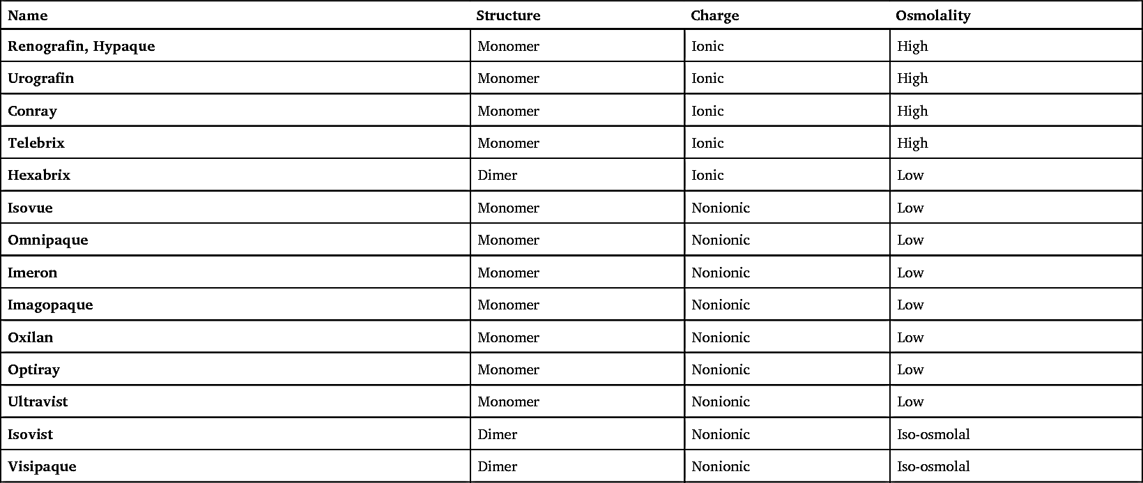
Table 14.1 presents a list of the iodine-based contrast agents.
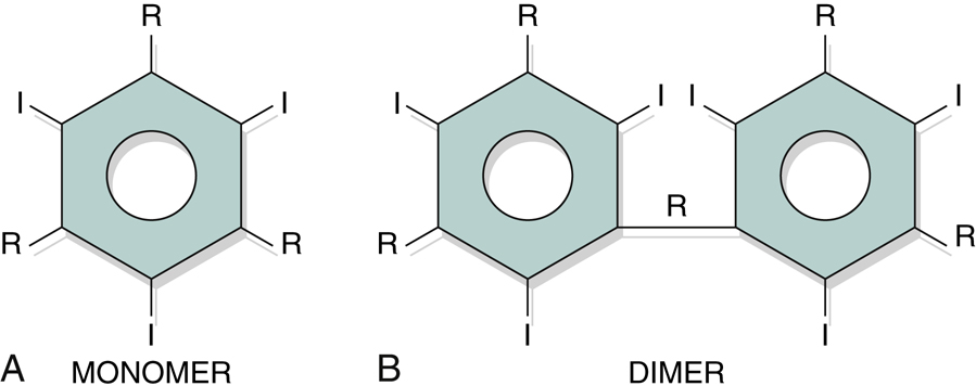
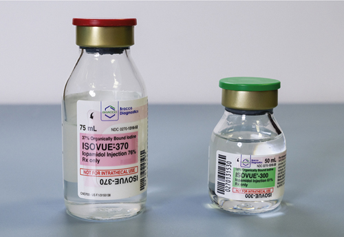
TABLE 14.1
| Name | Structure | Charge | Osmolality |
|---|---|---|---|
| Renografin, Hypaque | Monomer | Ionic | High |
| Urografin | Monomer | Ionic | High |
| Conray | Monomer | Ionic | High |
| Telebrix | Monomer | Ionic | High |
| Hexabrix | Dimer | Ionic | Low |
| Isovue | Monomer | Nonionic | Low |
| Omnipaque | Monomer | Nonionic | Low |
| Imeron | Monomer | Nonionic | Low |
| Imagopaque | Monomer | Nonionic | Low |
| Oxilan | Monomer | Nonionic | Low |
| Optiray | Monomer | Nonionic | Low |
| Ultravist | Monomer | Nonionic | Low |
| Isovist | Dimer | Nonionic | Iso-osmolal |
| Visipaque | Dimer | Nonionic | Iso-osmolal |
Common Side Effects
Side effects occur in many patients as an expected outcome of injected iodinated contrast medium. They are brief and self-limiting.
Two common side effects that may occur after an IV injection of iodinated contrast medium are a temporary hot flash and a metallic taste in the mouth. Both the hot flash, particularly in the face, and the metallic taste in the mouth usually last only minutes. Discussion of these possible effects and careful explanation of the examination help reduce patient anxiety and prepare the patient psychologically.
Patient History
A careful patient history may serve to alert the medical team to a possible reaction (Fig. 14.45). Patients with a history of allergies are more likely to experience adverse reactions to contrast media than those who have no allergies. Questions to ask the patient include the following:
-
- 1. Are you allergic to anything?
- 2. Have you ever had hay fever, asthma, or hives?
- 3. Are you allergic to any drugs or medications?
- 4. Are you allergic to iodine?
- 5. Are you allergic to any foods?
- 6. Are you currently taking metformin, Glucophage, Fortamet, Glumetza, Riomet, Glucovance, Metaglip, Jentadueto, ActoPlus Met, Prandimet, Avandamet, Kombiglyze XR, or Janumet 5 ?
- 7. Have you ever had an x-ray examination that required an injection into an artery or vein? If so, did you experience any difficulty with the injection of contrast media?
A positive response to any of these questions alerts the injection team to an increased probability of reaction.
Blood Chemistry
The technologist must check the patient’s chart to determine the creatinine and blood urea nitrogen (BUN) levels and/or the estimated glomerular filtration rate (eGFR). These laboratory tests should have been conducted and reported in the patient’s chart before the urinary system study is undertaken. Creatinine and BUN levels are diagnostic indicators of kidney function. An elevated creatinine or BUN level may indicate acute or chronic renal failure, tumor, or other conditions of the urinary system. Patients with elevated blood levels have a greater chance of experiencing an adverse contrast medium reaction. Normal creatinine levels for the adult are 0.6 to 1.5 mg/dL. The BUN level should range between 8 and 25 mg/100 mL. The eGFR has shown to be a more sensitive predicter of kidney function. A normal eGFR for adults is 60 mL/min or greater.
Metformin 5
Metformin hydrochloride is a drug that is given for the management of non-insulin-dependent diabetes mellitus. Metformin decreases hepatic glucose and increases the body’s response to insulin. Patients who are currently taking metformin can be given iodinated contrast media only if their kidney function levels are within normal limits. Because the combination of iodinated contrast medium and metformin may increase the risk for contrast medium–induced acute renal failure and/or lactic acidosis, the American College of Radiology recommends two categories for managing the risks:
-
- Category I: If a patient has no evidence of acute kidney injury (AKI) and has an eGFR of 30 mL or greater, there is no need to discontinue metformin use prior to or following injection.
- Category II: If a patient has an AKI or has an eGFR below 30 mL, Metformin should be withheld prior to injection and for 48 hours after the injection.
Individual site protocols may vary. The technologist must be aware of these policies prior to injecting contrast agents.
5
The technologist must review the patient’s chart and ask whether the patient is taking metformin. Trade names of medications that contain metformin include Glucophage, Glucophage XR, Fortamet, Glumetza, and Riomet. Combination products that contain metformin include Glucovance, Metaglip, Jentadueto, Actoplus Met, Actoplus Met XR, Prandimet, Avandamet, Janumet, Janumet XR, and Kombiglyze XR.
5
. If the patient says “yes,” this should be brought to the immediate attention of the radiologist before injection.
Selection and Preparation of Contrast Media
Selection and preparation of the correct contrast medium are important steps before injection (Fig. 14.46). Because labels on various containers are similar, one should always read the label very carefully several times. In addition, the empty container should be shown to the radiologist or the person who is making the actual injection. The empty contrast container should be kept in the examination room until the procedure is complete and the patient is dismissed, in the event a contrast reaction occurs. In some cases the lot number of the container must be documented as part of the patient file.


Reactions to Contrast Media
Preparation for Possible Reaction
Because a contrast medium reaction is possible and unpredictable, a fully stocked emergency response cart must be readily available whenever an IV injection is performed (Fig. 14.47). In addition to emergency drugs, the cart should contain cardiopulmonary resuscitation equipment, portable oxygen, suction and blood pressure apparatus, and possibly a defibrillator and monitor.
The technologist is responsible for ensuring that the emergency drug cart is stocked and available in the room. Masks and a cannula for oxygen support, suction tips, needles, and syringes must be readily available. The status of this equipment and the emergency drug cart should be verified before any contrast medium procedure is undertaken.
A common emergency drug is epinephrine, which should be available along with a syringe and needle ready for use (Fig. 14.48).
Premedication Procedure
To reduce the severity of contrast medium reactions, some patients may be premedicated before an iodinated contrast medium procedure is performed. The patient can be given a number of medications at different stages to reduce the risk of an allergic reaction to the contrast medium. One of the common premedication protocols includes a combination of an antihistamine and prednisone given over a period of 12 or more hours before the procedure. Patients who have a history of hay fever, asthma, or food allergy may be candidates for the premedication procedure. The technologist should ask patients whether they have received any premedication prior to the procedure and note their response in the appropriate chart.
Categories of Contrast Medium Reactions 5
There are two categories of contrast media reactions, local and systemic. Local reactions are those that affect only the specific region of the body at which the contrast medium has been injected into the venous system. Systemic reactions are those that do not affect the site of injection, but rather the entire body or a specific organ system. Systemic reactions can range from mild to severe. Severe reactions can lead to significant complications following the reaction.
Local reactions
Two local reactions to contrast medium injection can be found at or near the site of IV access. These include extravasation and phlebitis.
- • Extravasation: Leakage of iodinated contrast medium outside the vessel and into surrounding soft tissues (sometimes also referred to as infiltration). This can occur when venous access is lost due to breakage of the accessed vein or when the needle is improperly placed within the surrounding tissue outside the intended vein. In either case, the contrast medium fills the soft tissue surrounding the access site. Extravasated contrast medium, particularly high-osmolality contrast agents, is known to be toxic to surrounding tissues. Acute, local inflammatory response to the skin peaks 24 to 48 hours following extravasation of the contrast medium. Ulceration and tissue necrosis may result within 6 hours following the event. Although consensus regarding treatment has not been reached, a common protocol for extravasation includes the following:
-
- • Notify department nurse and/or physician so that treatment can be administered quickly.
- • Elevate the affected extremity above the heart to decrease capillary pressure and promote resorption of extravasated contrast medium.
- • Use a cold compress followed by warm compresses first to relieve pain and then to improve resorption of contrast medium.
- • Document the incident.


Outpatients should be released only after the radiologist has confirmed the initial signs and symptoms have improved and no new signs and/or symptoms have developed. Outpatients should be instructed to follow up with their physician should signs and symptoms worsen.
- • Phlebitis: Inflammation of a vein. This can be a complication of venous access related to the administration of IV contrast medium or simply venous access. Signs of phlebitis include pain, redness, and possibly swelling surrounding the venous access site.
-
- If signs of phlebitis are noted at the site a technologist intended to use for administration of the contrast medium, discontinue the venous access at this site and locate an alternative site above the affected area or on the opposite appendage. Phlebitis can escalate into a serious complication and should be documented in the patient’s chart. The attending nurse and/or physician should also be notified so that the site can be appropriately treated, if necessary.
Systemic reactions
Three general systemic categories of contrast media reactions have been identified: mild, moderate, and severe. These three reaction types are classified according to the degree of symptoms associated with the reaction.
Regardless of the type of contrast medium reaction that a patient may experience, it is important to document all symptoms in the patient’s chart and notify the attending nurse and/or physician.
- • Mild reaction: This nonallergic reaction typically does not require drug intervention or medical assistance (Fig. 14.49). Two of these symptoms are also considered side effects. This type of reaction may be based on anxiety and/or fear. Although this may not be a life-threatening situation, the technologist must be attentive to all needs of the patient. Symptoms of a mild reaction include the following (Table 14.2):

TABLE 14.2
| Symptoms | Technologist Responsibilities |
|---|---|
| All symptoms | Document all reactions to the contrast medium injection. Notify the attending nurse and/or physician of any unresolved reactions |
| Anxiety | Have patient take slow breaths and reassure patient. Continue to monitor patient. |
| Lightheadedness | Comfort and reassure patient. |
| Warm, flushed sensation, metallic taste | Comfort and reassure patient. |
| Nausea, vomiting | Have patient turn to side and provide emesis basin and cool washcloth (see Fig. 14.49). |
| Syncope (fainting) | Comfort and support patient and monitor vital signs. |
| Mild urticaria (scattered hives), itching | Inform nurse or physician. Continue to monitor patient. |
TABLE 14.3
TABLE 14.4
Possible treatment for a mild reaction might include having the patient breathe slowly, providing a cool washcloth, and reassuring the patient. Continue to observe the patient to ensure that these symptoms do not advance into a more serious reaction.
- • Moderate reaction: This second type of reaction is a true allergic reaction (anaphylactic reaction) that results from the introduction of iodinated contrast media. Symptoms of a moderate reaction include the following (Table 14.3):
Because moderate reactions may lead to a life-threatening condition, medical assistance must be provided without delay. Treatment often involves drug intervention to counter the effects of the reaction.
- • Severe reaction: This third type of reaction, also known as a vasovagal reaction, is a life-threatening condition. The introduction of iodinated contrast agents stimulates the vagus nerve, which may cause the heart rate to drop and the blood pressure to fall dangerously low. A fast response by the medical team is required. Symptoms of a severe reaction include the following (Table 14.4):
A medical emergency must be declared immediately. Ensure the emergency drug cart is nearby with oxygen and suction equipment available. Hospitalization for this patient is imminent.
A severe reaction may affect individual organ systems, leading to specific complications:
A contrast medium reaction may start immediately following the contrast medium injection or may not be identifiable for up to 48 hours after the study has been completed. Treatment may include monitoring, possible hydration, administration of Lasix (a diuretic), interventional cardiac medications, antiseizure medications, and renal dialysis. Because a contrast medium reaction may occur several hours after a procedure has been completed, the patient should be instructed to alert the physician of any difficulty in producing urine or other unusual symptoms.
Excretory Urography—Intravenous Urography (IVU)
Excretory urography or IVU, is a radiographic examination of the urinary system. This examination often has been referred to as intravenous pyelography, or IVP. Pyelo-, however, refers only to the renal pelvises. Because the excretory urogram normally visualizes more anatomy than just the renal pelvis, the term IVP is not an accurate term for this procedure and should not be used.
IVU visualizes the minor and major calyces, renal pelvises, ureters, and urinary bladder after an intravenous injection of contrast medium. IVU is a true functional test because the contrast medium molecules are rapidly removed from the bloodstream and excreted completely by the normal kidney. (Today functional studies of the urinary system are conducted more frequently with computed tomography [CT].)
Purpose
The three purposes of IVU are as follows:
Contraindications
Even though present-day contrast media are considered relatively safe, the technologist must take extra care in obtaining the patient history. Through the patient history, the technologist may become aware of certain conditions that prevent the patient from undergoing IVU. Major contraindications include the following:
- 1. Hypersensitivity to iodinated contrast media
- 2. Anuria, or absence of urine excretion
- 3. Multiple myeloma
- 4. Diabetes, especially diabetes mellitus
- 5. Severe hepatic or renal disease
- 6. Congestive heart failure
- 7. Pheochromocytoma (fe-o-kro″-mo-si-to′-mah)
- 8. Sickle cell anemia
- 9. Patients taking Metformin, Glucophage, Fortamet, Glumetza, Riomet, Glucovance, Metaglip, Jentadueto, ActoPlus Met, Prandimet, Avandamet, Kombiglyze XR, or Janumet 3
- 10. Renal failure, acute or chronic (see the section Glossary of Urinary Pathologic Terms)
Certain conditions on this list, such as multiple myeloma and pheochromocytoma, warrant additional consideration. Multiple myeloma is a malignant condition of the plasma cells of the bone marrow, and a pheochromocytoma is a tumor of the adrenal gland. Research has indicated that these patients are at greater risk during IVU. Because sickle cell anemia can compromise the function of the kidney, these patients are also at higher risk. A patient with one of the listed contraindications may require evaluation with some other imaging modality. However, a patient with any of these high-risk conditions may still undergo IVU if the physician determines that the benefits of the procedure outweigh the risks.
Hydration therapy of a normal saline IV drip and diuretic before the procedure is begun may reduce the risk for patients with multiple myeloma, diabetes mellitus, and other conditions. These patients also may be candidates for the premedication protocol before the contrast medium study is performed.
Glossary of Urinary Pathologic Terms
The following are common pathologic terms related to the urinary system that may be used to describe possible reactions to contrast media. These terms may be encountered in the patient’s chart, examination requisition, or procedure results report.
- Acute kidney injury (AKI) Formally known as acute renal failure (ARF); sudden kidney failure (see the term renal failure).
- Angioedema (an″-je-o-e-de′-ma) Regions or areas of subcutaneous swelling (e.g., in the lips, other parts of the mouth, eyelids, hands and feet) caused by an allergic reaction to food or drugs.
- Anuria (an-ur′-e-a) Complete cessation of urinary secretion by the kidneys; also called anuresis.
- Bacteriuria (bak-ter″-e-u′-re-a) Presence of bacteria in the urine.
- Bradycardia (brad″-e-kar′-de-a) Slowness of heartbeat, usually <60 beats/min.
- Bronchospasm (brong′-ko-spazm) Contraction of the bronchi and bronchiolar muscles, producing restriction of air passages.
- Diuretic (di″-u-ret′-ik) An agent that increases excretion of urine.
- Fecaluria (fe″-kal-u′-re-a) Fecal matter in the urine.
- Glucosuria (gloo″-ko-su′-re-a) Glucose in the urine.
- Hematuria (he″-ma-tu′-re-a) Blood in the urine.
- Hypotension (hi″-po-ten′-shun) Below normal arterial blood pressure.
- Laryngospasm (la-ring′-go-spazm) Closure of the glottic aperture within the glottic opening of the larynx.
- Lasix (la′-siks) Brand name for a diuretic.
- Lithotripsy (lith″-o-trip′-se) A therapeutic technique that uses acoustic (sound) waves to shatter large kidney stones into small particles that can be passed.
- Micturition (mik″-tu-ri′-shan) The act of voiding or urination.
- Nephroptosis (nef″-rop-to′-sis) Excessive inferior displacement of the kidney when erect.
- Oliguria (ol″-i-gu′-re-a) Excretion of a diminished amount of urine in relation to fluid intake, usually defined as less than 400 mL/24 hr; also called hypouresis and oligouresis.
- Pneumouria (noo″-mo-u′-re-a) Presence of gas in the urine, usually as the result of a fistula between the bladder and the intestine.
- Polyuria (pol″-e-u′-re-a) Passage of a large volume of urine in relation to fluid intake during a given period; a common symptom of diabetes.
- Proteinuria (pro″-te-nu′-re-a) The presence of excessive serum protein levels in the urine; also termed albuminuria.
- Renal agenesis (re′-nal a-jen′-a-sis) Absence of formation of a kidney.
- Renal failure (acute or chronic) The inability of a kidney to excrete metabolites at normal plasma levels, or the inability to retain electrolytes under conditions of normal intake.
-
- • Acute renal failure: Marked by uremia, oliguria, or anuria, with hyperkalemia and pulmonary edema; IVU demonstrates little or no contrast medium filtering through the kidney; possible exacerbation of patient’s condition following use of iodinated contrast media; ultrasound considered a safe alternative for evaluation of signs of renal failure.
- • Chronic renal failure: Results from a wide variety of conditions and may require hemodialysis or transplantation.
- Retention The inability to void, which may be due to obstruction in the urethra or lack of sensation to urinate.
- Syncope (sin′-ko-pe) Loss of consciousness caused by reduced cerebral blood flow; also known as fainting.
- Tachycardia (tak-i-kar′-de-a) Rapid heartbeat, usually >100 beats/min.
- Uremia (u-re′-me-a) An excess in the blood of urea, creatinine, and other nitrogenous end products of protein and amino acid metabolism; often present with chronic renal failure; also known as azotemia.
- Urinary incontinence Involuntary passage of urine through the urethra; commonly caused by failure of voluntary control of the vesical and urethral sphincters.
- Urinary reflux Backward or return flow of urine from the bladder into the ureter and kidney; also termed vesicoureteral reflux, a common cause of pyelonephritis, in which the backflow of urine may carry bacteria that can produce infection in the kidney.
- Urinary tract infection (UTI) Infection that frequently occurs in adults and children caused by bacteria, viruses, fungi, or certain parasites; commonly caused by vesicoureteral reflux.
- Urticaria (er″-ti-kar″-i-a) An eruption of wheals (hives) often caused by hypersensitivity to food or drugs.
Clinical Indications
The more common clinical indications for radiographic urinary system procedures include the following (Table 14.5).
- Benign prostatic hyperplasia (BPH) is an enlargement of the prostate that generally begins in the fifth decade of life. Although it is a benign condition, it may cause urethral compression and obstruction. This obstruction often produces painful and frequent urination and possible vesicoureteral reflux.
- The postvoid erect projection taken during IVU or cystography produces a defect along the base of the bladder indicative of BPH. The floor of the bladder may appear elevated and indented.
-
TABLE 14.5
Summary of Clinical Indications: Urinary System Condition or Disease Most Common Radiographic Examination Possible Radiographic Appearance Exposure Factor Adjustment Benign prostatic hyperplasia (BPH) IVU—erect postvoid or recumbent bladder, cystography Elevated or indented bladder floor None Bladder calculi Cystography, sonography—CT (preferred) Calcifications within bladder None Bladder carcinoma Cystography, CT, and MRI (preferred) Mucosal change within bladder None Congenital anomaliesDuplication of ureter and renal pelvisEctopic kidneyHorseshoe kidneyMalrotationIVU, sonography—CT Appearance dependent on nature of the anomaly None Cystitis Cystography Mucosal changes within bladder None Glomerulonephritis (Bright disease) IVU, sonography—nuclear medicine Acute—normal or enlarged kidneys with normal calyces; chronic—bilateral small kidneys, blunted calyces None Hydronephrosis IVU (nephrography), sonography, retrograde urography Enlarged renal pelvis and calyces and ureter proximal to obstruction; nephrogram becoming abnormally dense None Polycystic kidney disease (infantile, childhood, or adult) IVU (nephrography), CT, MRI Enlarged kidneys, elongated renal pelvis, radiolucency (cysts) throughout cortex None Prostate cancer IVU (erect position) sonography, MRI Elevated and distorted floor of contrast-filled bladder a None Pyelonephritis IVU (nephrography), sonography Chronic—patchy, blunting of calyces, with atrophy and thinning parenchyma None Renal calculi IVU, CT (preferred), nuclear medicine Signs of obstruction of urinary system None Renal cell carcinoma IVU, sonography—CT (preferred) Irregular appearance of parenchyma or collecting system None Renal hypertension Hypertensive IVU series, sonography (preferred) Small kidneys, with delayed excretion and overconcentration of contrast medium None Renal obstruction IVU, CT (tumor, stones) Signs of obstruction of the urinary system None Vesicorectal fistula (vesicocolonic) Cystography—barium enema, CT (preferred) Signs of inflammation or fluid collections None 
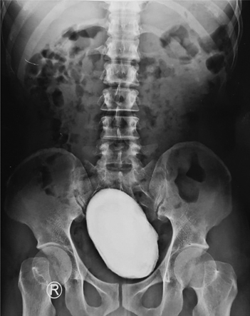
- Bladder calculi are stones that form in the urinary bladder. These stones are not as common as renal calculi, but they can grow large in the bladder (Fig. 14.50) and may be radiolucent or radiopaque. The radiolucent stones are most often uric acid stones. The presence of bladder stones can make urination difficult. These stones may be demonstrated during IVU or retrograde cystography. They also are seen clearly during a CT scan of the pelvis.
- Bladder carcinoma is a tumor that is three times more common in males than in females. 6 This tumor usually is diagnosed after the age of 50 years. Symptoms of bladder carcinoma include hematuria and frequency in urination. The tumor is often a solid or papillary mass with mucosal involvement. Although the cystogram may be performed, CT and magnetic resonance imaging (MRI) are used to stage the tumor and determine the extent of tissue involvement.
- Congenital anomalies are structural or chemical imperfections or alterations present at birth.
-
- • Duplication of the ureter and renal pelvis involves two ureters and/or the renal pelvis originating from the same kidney. It is the most common type of congenital anomaly of the urinary system. 6 This anomaly usually does not cause a health concern for the patient. The IVU confirms this condition.
- • Ectopic kidney describes a normal kidney that fails to ascend into the abdomen but remains in the pelvis. This type of kidney has a shorter than normal ureter. Although this condition does not pose a health concern for the patient, it may interfere with the birth process in females. Although IVU will confirm the location of the ectopic kidney, sonography and CT of the pelvis will also demonstrate this anomaly.
- • Horseshoe kidney occurs as a fusion of the kidneys during development of the fetus (Fig. 14.51). Almost 95% of cases involve fusion of the lower poles of the kidneys. 6 This fusion usually does not affect the function of the kidney. Because of fusion of the lower poles, the kidneys do not ascend to their normal position in the abdomen and are typically situated in the lower abdomen–upper pelvis. CT and sonography of the abdomen demonstrate this congenital condition, as does IVU.
- • Malrotation is an abnormal rotation of the kidney that is evident when the renal pelvis is turned from a medial to an anterior or a posterior direction. The UPJ may be seen lateral to the kidney. Usually, malrotation does not produce major complications for the patient.
- Cystitis (sis-ti′-tis) describes an inflammation of the urinary bladder caused by a bacterial or fungal infection. It is seen most often in females because of the shorter urethra that more readily permits retrograde passage of bacteria into the bladder. Laboratory tests confirm the presence of infection. The cystogram may demonstrate signs of chronic cystitis in the form of mucosal edema.
- Glomerulonephritis (glo-mer″-u-lo-na-fri′-tis) (also known as Bright disease) is an inflammation of the capillary loops of the glomeruli of the kidneys. (Nephritis indicates inflammation of the nephron.)
-
- • It occurs in acute, subacute, and chronic forms. With acute glomerulonephritis, the IVU may demonstrate an enlarged kidney with reduced concentrations of contrast medium in the collecting system. Sonography is the modality of choice and may show an enlarged, echolucent kidney with acute conditions.
- • With the chronic condition, sonography demonstrates small kidney size caused by fibrosis and cortex destruction from long-standing inflammation. Thus, chronic forms of this disease result in small kidneys with blunt, rounded calyces. This condition is the most common cause of undeveloped kidneys in young adults. 7 It is characterized by hypertension and increased serum levels of BUN and creatinine. It may also result in increased levels of albumin in the urine.
- • Nuclear medicine may be performed to demonstrate functional changes within the nephron caused by infection or restriction of blood flow through the capillary beds.
- Hydronephrosis (hi″-dro-na-fro′-sis) is a distention of the renal pelvis and calyces of the kidneys that results from some obstruction of the ureters or renal pelvis. It may be present in both kidneys in a woman when the ureters are compressed by the fetus. Other, more common causes are calculi (stones) in the renal pelvis or ureter, tumors, and structural or congenital abnormalities (Figs. 14.52 and 14.53).
- Polycystic kidney disease is a disorder marked by cysts scattered throughout one or both kidneys. This disease is the most common cause of enlarged kidneys. 7 Its cause may be genetic or congenital, depending on the type of polycystic disease. These cysts alter the appearance of the kidney and may alter renal function. In some cases, the liver may also have cysts.
- The appearance of polycystic disease is described as a “bunch of grapes” scattered throughout the kidney. 6 Three major types of polycystic kidney disease include infantile, childhood, and adult. (See Chapter 16 for a description of infantile and childhood types.)
-
- • Adult: This form of polycystic disease is hereditary. Although the condition is present at birth, symptoms are not seen until later in life.
- Symptoms include renal hypertension, proteinuria, and signs of chronic renal failure. If a cyst ruptures into a calyx, it may produce hematuria. The nephrogram or nephrotomogram taken during IVU may provide an indirect sign of cysts. High-resolution CT does an excellent job of demonstrating radiolucent regions characteristic of cysts, as does ultrasound and MRI.
- Prostate carcinoma: The second most common malignancy in males over the age of 50 years. It is often a slow growing tumor and may not be detected for years. The most common metastases of prostate cancer is to bone 8 (Fig. 14.54).
- IVU may demonstrate reduced excretion of contrast medium due to tumor involvement, but sonography and CT are the modalities of choice for demonstrating the extent of the tumor and its impact on surrounding tissues.
- Pyelonephritis (pi″-a-lo-na-fri′-tis) describes an inflammation of the kidney and renal pelvis caused by pyogenic (pus-forming) bacteria. The inflammation process primarily affects the interstitial tissue between the tubules, whereas glomerulonephritis, described earlier, involves the glomeruli and tubules themselves.
- With acute pyelonephritis, the intravenous urogram is frequently normal, but with chronic pyelonephritis, the hallmark urographic sign is patchy and blunted or rounded calyces with atrophy and thinning of renal parenchyma.
- Renal calculi are calcifications that occur in the luminal aspect of the urinary tract (Figs. 14.55 and 14.56). These calcifications often lead to renal obstruction. Calcifications also occur in the renal parenchyma.
- The causes of stone formation remain uncertain. Research indicates that patients with very acidic urine (pH 5 to 6) and elevated levels of calcium in the urine have a greater incidence of renal stones. Conditions that may produce elevated levels of calcium in the urine include hyperparathyroidism, bone metastasis, and multiple myeloma. Abnormal ingestion of calcium may increase the risk for renal calculi.
- Although IVU demonstrates obstruction caused by renal calculi, CT of the urinary tract has become the gold standard for detecting stones.
-
- • A staghorn calculus is a large stone that grows and fills the renal pelvis completely, blocking the flow of urine (Fig. 14.57). This type of stone most commonly is associated with chronic urinary tract infections (UTIs).
- Renal cell carcinoma (hypernephroma) is the most frequent type of malignant tumor of the kidney. 6 It is three times more frequent in males than females. Symptoms include flank pain and hematuria. The tumor itself is typically a large irregular mass with internal areas of necrosis and hemorrhage.
- Renal hypertension is increased blood pressure to the kidney through the renal artery due to atherosclerosis. This form of hypertension results from increased excretion of renin, which results in excessive vasoconstriction.
-
- • Severe hypertension can result in localized necrosis of the renal parenchyma and small kidneys, with delayed excretion and overconcentration of contrast medium. Diabetes in conjunction with renal hypertension can accentuate the damage to the kidney.
- • Renal hypertension often requires an alteration of the normal IVU routine. The filming sequence for the study allows for shorter spans of time between images. (The hypertensive IVU examination, which has largely been replaced by alternative modalities, is described more completely in a later section of this chapter.)
- Renal obstruction may be caused by necrotic debris, calculus, thrombus, or trauma. Renal obstruction from any source may lead to renal damage. The longer the obstruction persists, the greater is the chance of functional injury.
-
- • Acute obstruction: During IVU, the nephrogram demonstrates reduced perfusion of contrast medium through the kidney. Delayed opacification of the collecting system is another sign of acute obstruction. It may be hours after injection before the contrast medium is visible in the collecting system. This delay may require the technologist to take delayed films several hours after injection.
- • Chronic or partial obstruction: During IVU, the collecting system may be opacified, but the calyces may show signs of enlargement and hydronephrosis.
- Vesicorectal (vesicocolonic) fistula is a fistula (artificial opening) that forms between the urinary bladder and rectum or aspects of the colon. This condition may be due to trauma, tumor, or congenital defect.
- Approximately 60% of fistulas result from diverticulosis (outpouching or herniation of an organ wall, usually in the small or large intestine). Another 20% are caused by an invading carcinoma, colitis, or trauma. 6 Pneumaturia and fecaluria are symptoms of a fistula.
- Although a barium enema and cystography are performed to determine whether a fistula is present, they visualize only approximately 50% of the condition. CT is recommended to demonstrate signs of inflammation or air in the bladder, which may indicate a fistula.


Patient Preparation
Patient preparation for IVU and the barium enema is similar. The intestinal tract should be free of gas and fecal material for both examinations. If they are to be performed on the same patient, they can be done on the same day. The IVU is done first, with the barium enema to follow.
General patient preparation for IVU includes the following:
Before the excretory urogram is performed, all clothing except shoes and socks should be removed and replaced with a short-sleeved hospital gown. The opening and ties should be in the back.
The patient should void just before the examination is performed for these two reasons:
Some department policies may require patients to urinate through a filter if the IVU study has been ordered to evaluate for renal stones.
Pregnancy Precautions
If the patient is a female, a menstrual history must be obtained. Irradiation of early pregnancy is one of the most hazardous situations in diagnostic radiography.
X-ray examinations, such as an IVU, that include the pelvis and uterus in the primary beam should be performed on pregnant females only when absolutely necessary and when the benefits exceed the risks. Abdominal radiography of a known pregnancy should be delayed until the third trimester if performed at all.
In certain cases IVU for a pregnant patient may be requested. Frequently it is ordered to rule out urinary obstruction. In these situations the technologist should communicate with the radiologist to determine whether the number of radiographs taken during the IVU can be reduced. A reduction in the number of projections taken may be the best way to reduce dose to the fetus. The use of a higher kV, with lower mAs exposure factors, also reduces patient exposure.
Preparation of Radiographic Equipment and Supplies
Equipment and supplies needed for urography, in addition to a suitable radiography room, include the following (Fig. 14.58):
- 1. Correct type and amount of contrast medium drawn up in an appropriate syringe
- 2. The empty container of contrast medium to show the physician or assistant who is performing the injection
- 3. A selection of sterile needles, including 18-, 20-, and 22-gauge over-the-needle catheter and butterfly needles and tubing
- 4. Alcohol sponges or wipes
- 5. Clean procedure gloves
- 6. Tourniquet
- 7. Towel or sponge to support the elbow
- 8. Sharps container
- 9. Male gonadal shield
- 10. Emesis basin
- 11. Lead numbers, minute marker, and R and L markers
- 12. Emergency cart accessible
- 13. Epinephrine or Benadryl ready for emergency injection
- 14. Ureteric compression device (if used by department)
- 15. A cold towel for the forehead and/or injection site, and a warm towel if necessary
- 16. Operational and accessible oxygen and suction devices

These items should be assembled and ready before the patient is escorted to the radiography room.
Ureteric Compression
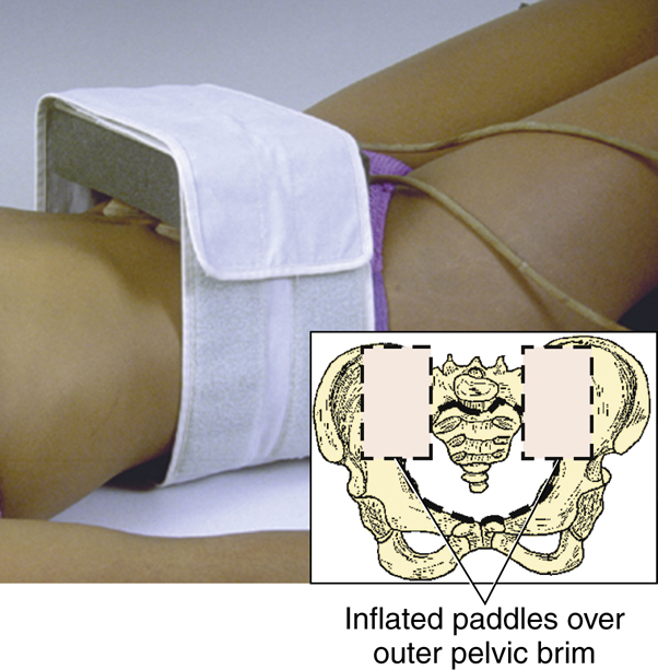
Ureteric compression is a method used to enhance filling of the pelvicalyceal system and proximal ureters. Furthermore, ureteric compression allows the renal collecting system to retain the contrast medium longer for a more complete study. A compression device is shown on the model in Fig. 14.59. It is a Velcro band that wraps around two inflatable pneumatic paddles. These paddles are held in place by a piece of Plexiglas and a sponge.
Before the contrast medium is injected, the device is placed on the patient, with the paddles deflated. The two paddles must be placed over the outer pelvic brim on each side to allow for compression of the ureters. The inner edges of the paddles should almost touch just lateral to the vertebral spine on each side. The greatest pressure is exerted in the center of the inflated paddles, which should be positioned over the point at which the ureters cross the psoas muscles. Without proper placement of the paddles, the contrast medium is excreted at its normal rate (see Fig. 14.59, inset).
Once the contrast medium has been introduced, the paddles are inflated and remain in place until the postcompression images are ready to be obtained.
Contraindications to Ureteric Compression
Certain conditions contraindicate the use of ureteric compression, including the following:
-
- 1. Possible ureteric stones (difficult to distinguish between the effects of compression versus the appearance caused by a stone)
- 2. Abdominal mass (may present the same radiographic appearance as ureteric compression)
- 3. Abdominal aortic aneurysm (compression device may lead to leakage or rupture of the aneurysm)
- 4. Recent abdominal surgery
- 5. Severe abdominal pain
- 6. Acute abdominal trauma
Alternative: Trendelenburg Position
The Trendelenburg position (wherein the head end of the table is lowered about 15°) provides some of the same results as the compression procedure without as much risk to the patient whose symptoms contraindicate ureteric compression (Fig. 14.60).
General Intravenous Urography Procedure
This section introduces a generic procedure for IVU; however, department routines vary. The department supervisor should be consulted for specific differences from the following description.
Scout Image and Injection
The patient’s clinical history and other pertinent information are discussed with the radiologist before injection. The scout radiograph is taken for the following reasons: (1) to verify patient preparation; (2) to determine whether exposure factors are acceptable; (3) to verify positioning; and (4) to detect any abnormal calcifications. These scout radiographs should be shown to the radiologist before injection. If the patient has a urinary catheter in place, it should be clamped before injection.
When the injection is made, the exact start time and duration of injection should be noted. Timing for the entire series is based on the start of the injection, not the end of it. The injection usually takes 30 to 60 seconds and 1 minute to complete (Fig. 14.61). As the examination proceeds, the patient should be observed carefully for any signs or symptoms indicating a reaction to the contrast medium. Most contrast medium reactions will occur within the first 5 minutes following injection. Delayed reactions may also occur. The chart should note the amount and type of contrast medium given to the patient.
After the full injection of contrast medium, radiographs are taken at specific time intervals. Each image must be marked with a lead number that indicates the time interval when the radiograph was taken.
Basic Imaging Routine (Sample Protocol)
A common routine for IVU is as follows (Box 14.1):
- 1. A nephrogram or nephrotomogram is taken immediately after completion of injection (or 1 minute after the start of injection) to capture the early stages of entry of the contrast medium into the collecting system (additional description on following page).
- 2. A 5-minute image requires a full image of the kidneys, ureter, and bladder (KUB) to include the entire urinary system. The supine position (anteroposterior [AP]) is the preferred position.
- 3. A 10- to 15-minute image requires a complete KUB to include the entire urinary system. Once again, the supine position (AP) is most commonly requested.
- 4. A 20-minute oblique usually requires LPO and RPO positions to provide a different perspective of the kidneys and project the ureters away from the spine.
- 5. A postvoid radiograph is taken after the patient has voided. The positions of choice may include a prone (posteroanterior [PA]) or erect AP. The bladder should be included on this final radiograph.
NOTE: Prior to exposure, ensure that time markers are placed on the IR to record the time of exposure.


Alternatives to Routine Examination
There are many variations or alternatives to the basic routine, and the radiologist may order specific positions at any time during the study. Three common variations include the following.
- 1. Postrelease or “spill” procedure with ureteric compression
- A full-size radiograph is taken after compression has been released. The procedure is explained to the patient and the air pressure is released, as illustrated in Fig. 14.62. The spill radiograph or any other delayed imaging usually is done with the patient in the supine position.
- To assess for asymmetric renal function, compression may be applied immediately after the 5-minute exposure (unless contraindicated) and then removed immediately before the 15-minute image.
- 2. Erect position for bladder
- If the patient has a history of prolapse of the bladder or an enlarged prostate gland, the erect bladder position taken before voiding may confirm these conditions.
- 3. Delayed radiographs
- Often, with urinary calculi, filling of the involved ureter is slow. The patient may be brought back to the department on a 1- or 2-hour basis. The radiology staff should be aware of when the next radiograph is due before leaving the department for the day.
After completion of the usual IVU series, a postvoid radiograph is often obtained with the patient in the prone or upright position. Through emptying of the bladder, small abnormalities may be detected. The upright position also demonstrates any unusual movement of the kidneys.
The radiologist should confirm that no additional images are required before releasing the patient from the department.
Nephrogram Versus Nephrotomogram
Radiographs taken very early in the series are termed nephrograms (nef′-ro-grams). The renal parenchyma or functional portion of the kidney consists of many thousands of nephrons. Because individual nephrons are microscopic, the nephron phase is a blush of the entire renal parenchyma. This blush results from dispersion of contrast medium throughout the many nephrons, but not yet into the collecting tubules. The usual nephrogram is obtained with a radiograph at 1 minute after the start of injection. Ureteric compression, if used, tends to prolong the nephron phase to as long as 5 minutes in the normal kidney.
The most common imaging obtained during the nephron phase is a tomographic nephrogram, called a nephrotomogram, as opposed to a nontomographic nephrogram. Three separate focal levels are commonly taken with a nephrotomogram (Fig. 14.63) during this phase of the study. (See Chapter 19 for principles of conventional tomography.)
Because the primary interest in nephrography is the kidneys, centering and IR size should be confined to the kidneys. Centering should be halfway between the iliac crest and xiphoid process unless a better centering point is determined after the scout radiograph is viewed.
For determination of the initial fulcrum level, one method is to measure the thickness of the mid-abdomen using calipers. Once this number has been obtained, it is divided by 3. Therefore, with an abdomen that is 24 cm thick, one would first set the fulcrum at 8 cm. If the patient is lying on a thick pad or mattress, 1 cm is added to this calculation, which then results in an initial fulcrum setting of 9 cm.
Timing is critical on this radiograph, so the exposure must be made exactly 60 seconds after the start of the injection. The table, IR, and control panel must be set before the injection is initiated because the injection sometimes takes almost 60 seconds to complete.
Hypertensive Intravenous Urography
Purpose
A special type of IV urogram is the hypertensive urogram. This examination is performed on patients with high blood pressure (hypertension) to determine whether the kidneys are the cause of the hypertension. A much shorter time is allowed between projections for a hypertensive IV urogram compared with a standard IVU procedure.
Procedure
During hypertensive urography, several early radiographs must be obtained. All image receptors must be available and marked with lead numbers to reflect the time sequence of each image. Once the procedure begins, radiographs must be taken at set intervals.
The hypertensive study includes at least 1-, 2-, and 3-minute radiographs, with the possibility of additional radiographs every 30 seconds. In most cases, timing begins at the start of injection.
After the initial radiographs, the imaging sequence may be similar to that of a standard IVU with imaging of the ureters and bladder.

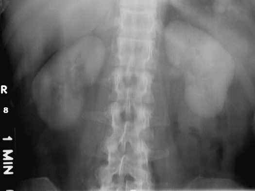
Retrograde Urography
Purpose
Retrograde urography is a nonfunctional examination of the urinary system. Contrast medium is introduced directly retrograde (backward, against the flow) into the pelvicalyceal system via catheterization by a urologist during a minor surgical procedure. Retrograde urography is nonfunctional because the patient’s normal physiologic processes are not involved in the procedure. This procedure is performed to determine the location of urinary calculi or other types of obstruction.
NOTE: This procedure is less frequently performed today because of the increased use of CT for locating urinary calculi or obstruction within the urinary system.
Procedure
The patient is placed on the combination cystoscopy-radiography table, which is usually located in the surgery department. The patient is placed in the modified lithotomy position, which requires that the legs be placed in stirrups, as illustrated in Fig. 14.64. The patient is typically sedated or anesthetized for this examination. Additional details of this procedure are discussed in the section on surgical procedures in Chapter 15.
Retrograde Cystography
Purpose
Retrograde cystography (sis-tog′ra-fe) is a nonfunctional radiographic examination of the urinary bladder that is performed after instillation of an iodinated contrast medium via a urethral catheter. Cystography is a common procedure for ruling out trauma, calculi, tumor, and inflammatory disease of the urinary bladder.
Procedure
No patient preparation is required for this examination, although the patient should empty the bladder prior to catheterization. After routine bladder catheterization is performed under aseptic conditions, the bladder is drained of any residual urine. The bladder then is filled with contrast medium, as illustrated in Fig. 14.65. The contrast material is allowed to flow in by gravity only. One should never hurry or attempt to introduce the contrast medium under pressure, which could result in rupture of the bladder.
After the bladder is filled, which may require 150 to 500 mL, fluoroscopic spot radiographs are taken by the radiologist, or various overhead positions may be exposed by the technologist.
Routine positioning for a cystogram includes an AP, with a 15° caudad angle and bilateral posterior oblique positions.


Voiding Cystourethrography
purpose
Voiding radiographs may be taken after the routine cystography is complete. When images are combined in this manner, the examination is termed cystourethrography (sist″-to-u″-re-throg′ra-fe), or voiding cystourethrography (VCU). This examination provides a study of the urethra and evaluates the patient’s ability to urinate; therefore, it is a functional study of the bladder and urethra.
Clinical Indications
Trauma, posterior urethral valves, and incontinence are common clinical indications for a VCU examination. Posterior urethral valves are small leaflets of tissue that have a narrow, slitlike opening that partially impedes urine outflow.
9
Procedure
The voiding phase of the examination is best conducted using a fluoroscopy unit with image acquisition capability. The procedure is sometimes performed with the patient supine, although the upright position makes voiding easier. Before the catheter is removed from the bladder and urethra, all liquid must first be drained from the balloon portion of the catheter if this type of catheter is being used. Then the catheter is removed very gently. The urethra can be traumatized if care is not exercised.
The female is usually examined in the AP or slight oblique position, as shown on the radiograph in Fig. 14.66. The male is best examined in a 30° right posterior oblique position. An adequate receptacle or absorbent padding must be provided for the patient. Conventional or digital fluoroscopy may be used to capture specific phases of voiding.
After voiding is complete and adequate imaging is obtained, a postvoid AP may be requested.
Retrograde Urethrography
Purpose
Retrograde urethrography sometimes is performed on the male patient to demonstrate the full length of the urethra. Contrast medium is injected retrograde into the distal urethra until the entire urethra is filled (Fig. 14.67).
Clinical Indications
Trauma and obstruction of the urethra are clinical indications for this procedure.
Procedure
Injection of contrast material sometimes is facilitated by a special device termed a Brodney clamp (Fig. 14.68), which is attached to the distal penis.
A 30° right posterior oblique is the position of choice, with centering to the symphysis pubis. The special catheter is inserted into the distal urethra and the contrast medium is administered by injection. Ample contrast medium is used to fill the entire urethra, and exposures are made. An RPO retrograde urethrogram of a male patient is shown in Fig. 14.67. Ideally, the urethra is superimposed over the soft tissues of the right thigh. This position prevents superimposition of any bony structures except for the lower pelvis and proximal femur.

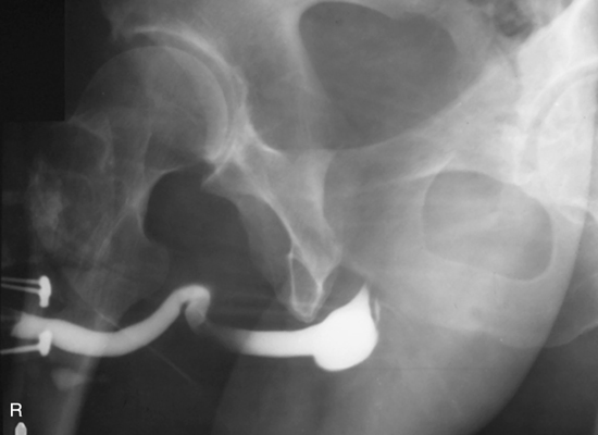

Summary of Urinary System Procedures
Urographic procedures may be categorized by the method of contrast medium administration used (Table 14.6). The contrast medium is introduced into the circulatory system or directly into the structure to be studied.
Special Patient Considerations
Pediatric Applications
The physiology of the pediatric patient is sensitive to changes in diet, fluid intake, and the presence of iodinated contrast media. Therefore, patient preparation for IVU of an infant or young child must be monitored carefully. Restricting fluids for a long time before the procedure is performed may cause severe dehydration, which can lead to added risk for a contrast medium reaction. Pediatric patients must be scheduled early in the day, so that they can return to a normal diet after the procedure. Furthermore, the technologist must carefully monitor the patient throughout the procedure.
The increased use of sonography for a variety of urinary conditions has provided a safer method (without radiation) of evaluating the pediatric patient.
Geriatric Applications
Similar to pediatric patients, the older patient may be negatively affected by the change in diet and fluid intake before IVU. The technologist must monitor the older patient carefully during this procedure.
Because some older patients have a clinical history of diabetes, the technologist must ask whether they are taking the type 2 diabetes medications listed earlier. As noted, the use of iodinated contrast media may be contraindicated for patients who are taking these drugs.
Bariatric Patient Considerations
Technical factors may need to be increased for bariatric patients to penetrate excess adipose tissue. Bariatric patients may need additional assistance with moving between images. The panniculus (dense layer of fatty tissue growth, consisting of subcutaneous fat in the lower abdomen) may also need to be managed in an effort to visualize the bladder during postvoid or cone-down bladder images.
Digital Imaging Considerations
Digital imaging considerations for all urographic procedures, including IVU, are similar to those for other abdominal projections, as described in detail in Chapter 3 for the abdomen. These include (1) close collimation; (2) accurate centering of the central ray (CR) to the body part of interest and to the IR; and (3) optimal exposure factors, remembering the ALARA principle (exposure to patient
a
s
l
ow
a
s
r
easonably
a
chievable), which is confirmed by the (4) post-processing evaluation of exposure indicators.
Alternative Modalities and Procedures
Computed Tomography (CT)
The use of CT for renal studies has grown. It is an ideal modality for the evaluation of renal tumors and urinary obstructions. In many imaging departments, CT of the urinary system for renal calculi has replaced the IVU study. The patient does not require extensive bowel prep, and the location of the stone can be accurately pinpointed.
A high-speed, multi-detector CT scanner can be used to examine the entire urinary system quickly and efficiently. Contiguous, fine transverse slices from the kidneys through the urinary bladder can provide a noninvasive assessment for stones without the use of iodinated contrast media. This procedure, CT urography, also does not require any bowel prep, which often makes it the examination of choice.
CT departments are also performing what is referred to as a CT IVU (Fig. 14.69A). This procedure closely mimics protocols once regularly used in the diagnostic imaging department for IVU. The CT IVU typically requires the patient’s bowel to be prepped with 32 oz of water at least 1 hour prior to the procedure. Once the patient has been prepped and centered on the CT table, an initial set of thin slice, contiguous, noncontrast images are taken from the top
of the kidneys through the bottom of the urinary bladder to evaluate for the presence and location of renal calculi. Noncontrast images are ideal because the attenuation factor of contrast and calculi are similar. Therefore, the use of contrast will preclude visualization of a calculi if present (Fig. 14.69B). Iodinated contrast medium then is introduced into the venous system using a power injector. A second set of contiguous images is taken at approximately 60 seconds from the start of the injection. This time, the images start just above the diaphragm through the pubic symphysis in an effort to evaluate the entire abdominal and pelvic cavities and the kidneys, ureters, and bladder post-contrast injection. Finally, a set of delayed images is again taken from just above the kidneys through the urinary bladder in an attempt to visualize the contrast-filled ureters. The time delay from the start of injection to initiation of the delayed image series can range from 5 to 10 minutes, depending on department protocol. Department protocol may also include three-dimensional reconstructions of the final delayed image series to demonstrate the entire contrast-filled urinary system.

TABLE 14.6
CT has become the imaging modality commonly used for the evaluation and location of renal calculi because of the speed of the study and its ability to visualize the urinary system without superimposition of external structures. CT also provides physicians with the option to use iodinated contrast media or not, depending on the desire for a structural or structural and functional study.
CT Dose Reduction Measures
The potential for high radiation exposure during CT is always on the mind of physicians and technologists. Many efforts have been made to improve the radiation safety measures used during CT series. Exposure factors can be adjusted to compensate for a decrease or increase in body size according to the patient’s height and weight. Software applications can be initiated to decrease exposure as body part thickness decreases. Many facilities now also have the ability to conduct low-dose studies, which produce noisy images of lower diagnostic quality but may be appropriate for follow-up procedures and imaging of pregnant women. When the radiologist requires only a general overview, this option can save the patient and/or fetus exposure while still providing the necessary information.
Shielding during a CT procedure is always a possibility to decrease unnecessary patient exposure. It is important to remember that the radiation beam travels 360° around the patient, so lead shielding must follow this same pattern to be most effective. Special CT shields are now available to protect specific radiosensitive body parts such as the breasts, eyes, and thyroid during a procedure. These can even be placed over the breasts (Fig. 14.70) during chest CT or over the eyes during head CT. The materials used to create the shield do not interfere with image production like classic lead shielding. It is important to remember that these shields do not completely protect the tissues, but decrease their exposure. Other radiation exposure–reducing measures should still be used along with these shields.
Sonography (Ultrasound)
Sonography provides a means to evaluate the kidney and bladder in a noninvasive manner. The filled bladder provides an acoustic window for demonstrating bladder calculi or masses in the bladder or organs that surround the bladder, such as the uterus. Ultrasound can also be used to evaluate the kidney to determine whether cysts or masses are present. It is the imaging modality of choice for evaluating the transplanted kidney. Sonography, along with nuclear medicine, can be used to measure parenchymal perfusion. Reduced blood flow or perfusion may be an indication of tissue rejection.
Endorectal ultrasound is highly effective for imaging of the prostate. It can be used to distinguish among solid, cystic, and mixed tissue masses in the prostate gland.
Magnetic Resonance Imaging (MRI)
MRI is used to demonstrate subtle tissue changes in the urinary bladder and kidney. It can also be used to evaluate tumors, renal transplants, and patency of the renal artery and vein. On T1-weighted images, the kidney is well defined in contrast to the fat-laden perirenal space. Coronal, sagittal, and transverse perspectives of the urinary system provide a means of determining the spread of select tumors of the kidney to adjacent structures.
Nuclear Medicine (NM)
Specific NM procedures can measure renal function and excretion rates. NM studies provide a functional evaluation of the kidneys. They provide a less hazardous method of evaluating the kidneys for signs of chronic or acute renal failure without the use of iodinated contrast media. This is especially true in the evaluation of a transplanted kidney. Subtle signs of organ rejection can be seen in the degree of perfusion of radionuclides in the nephrons.
Radionuclides are also being used to determine whether a physical blockage exists in the ureter and to evaluate for vesicoureteral reflux. In the case of vesicoureteral reflux, the patient’s bladder is filled with saline and a very small amount of radioactive material is instilled. During the act of voiding, any trace of reflux can be tracked and filmed.
In general, the role of NM in evaluating renal anatomy has been decreasing, but its use for confirming and analyzing renal function has increased.
Routine and Special Projections

AP Projection (Scout and Series): Intravenous (Excretory) Urography
Clinical Indications
After injection, the AP projection may demonstrate signs of obstruction, hydronephrosis, tumor, or infection. See p. 552 for the IVU routine.
Technical Factors


Shielding
Shield radiosensitive tissues outside the region of interest.
Patient Position
Situate the patient supine, with a pillow for the head, arms at the sides, away from the body, and support under the knees to relieve back strain.
Part Position

- • Align midsagittal plane to centerline of table and to CR.
- • Ensure no rotation of trunk or pelvis.
- • Include symphysis pubis on bottom of IR without cutting off upper kidneys (Fig. 14.71). (A second smaller IR for bladder area may be necessary on hypersthenic patients.)
CR
Recommended Collimation
Collimate on all four sides to anatomy of interest.
Respiration
Suspend respiration after expiration and expose.
NOTE: Have patient empty bladder immediately before beginning the examination so that contrast medium in the bladder is not diluted. Explain procedure and obtain a clinical history before injecting contrast medium. Be prepared for possible reaction to the contrast medium.


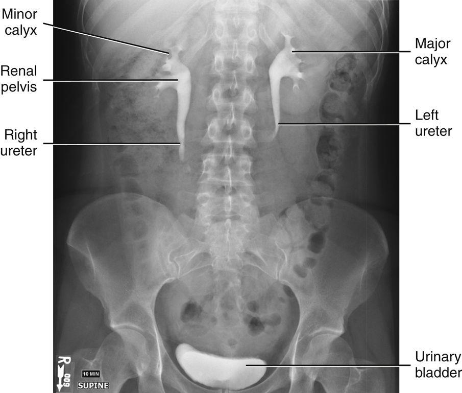
Nephrotomography and Nephrography: Intravenous (Excretory) Urography
Clinical Indications
Renal cysts and/or adrenal masses may be demonstrated during this phase of IVU. A nephrogram involves a single AP radiograph of the kidney region taken within 60 seconds after injection.
Technical Factors

Shielding
Shield radiosensitive tissues outside the region of interest.
Patient Position
Position the patient supine, with a pillow for the head, arms at the sides, away from the body, and support under the knees to relieve back strain.
Part Position
- • Align midsagittal plane to centerline of table or grid (Fig. 14.74).
- • Ensure no rotation of trunk or pelvis.
CR
Recommended Collimation
Collimate on four sides to anatomy of interest.
Respiration
Suspend respiration after expiration and expose.
NOTE: Explain tomographic procedure to reduce anxiety for patient. Obtain a clinical history before injection of contrast medium. Remind the patient to remain immobile between exposures. Check scout image to verify focus level, optimal technique, and position of kidneys. Tomography procedures, including equipment setup and procedure, are described in Chapter 19.
Evaluation Criteria
Anatomy Demonstrated:
- • Entire renal parenchyma is visualized, with some filling of collecting system with contrast medium (Fig. 14.75).
Position:
Exposure:
Markers:

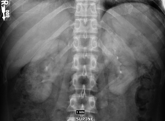
RPO and LPO Positions: Intravenous (Excretory) Urography
Clinical Indications
Technical Factors


Shielding
Shield radiosensitive tissues outside the region of interest.
Patient Position
The patient is supine and is partially rotated toward the right or left side.
Part Position
- • Rotate body 30° for both R and L posterior oblique positions (Fig. 14.76).
- • Flex elevated-side knee for support of lower body.
- • Raise arm on elevated side and place across upper chest.
- • Center vertebral column to midline of table or grid and to CR.
CR
Recommended Collimation
Collimate on four sides to anatomy of interest.
Respiration
Suspend respiration after expiration and expose.
NOTE: Some department routines include a smaller IR placed landscape to include the kidneys and proximal ureters, thus allowing gonadal shielding for males and females. Centering then would be midway between the xiphoid process and iliac crests.
Evaluation Criteria
Anatomy Demonstrated:
Position:
- • No excessive obliquity is evident. • The elevated kidney is parallel to the plane of IR and is not projected into the vertebral bodies of the lumbar spine. • Complete arch of symphysis pubis is visible on bottom margin of radiograph and the kidneys are included at the upper margin. • Proper collimation applied.
Exposure:
Markers:


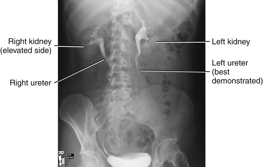
AP Projection: Intravenous (Excretory) Urography
Postvoid
Clinical Indications
Technical Factors

Shielding
Shield radiosensitive tissues outside the region of interest.
Patient Position
Part Position
CR
Recommended Collimation
Collimate on four sides to anatomy of interest.
Respiration
Suspend respiration after expiration and expose.
Alternative PA or AP Recumbent
This image also may be taken as a PA or AP projection in the recumbent position, with centering similar to that described earlier.
Evaluation Criteria
Anatomy Demonstrated:
- • Entire urinary system is included, with only residual contrast medium visible (Fig. 14.81). • All of symphysis pubis (including prostate area on males) is included on radiograph.
Position:
Exposure:
Markers:


AP Projection: Intravenous (Excretory) Urography
Ureteric Compression
WARNING: Compression should not be used for patients with a history of abdominal masses, obstructions (e.g., stones), abdominal aortic aneurysms, or recent surgery. (See the section Contraindications to Ureteric Compression. A Trendelenburg position with 15° tilt, which approximates the same effect, can be used for these patients.)
Clinical Indications
Technical Factors

Shielding
Shield radiosensitive tissues outside the region of interest.
Patient Position
Part Position
- • Align midsagittal plane to centerline of table or grid and to CR.
- • Flex and support knees.
- • Position arms away from body.
- • Place upper edge of compression paddles at level of iliac crest. Inner edges of paddles should almost touch, just lateral to the vertebral spine on each side. (This places maximum pressure over the area of the ureters, which are just lateral to the lumbar spine and medial to the sacroiliac [SI] joints.)
CR
Recommended Collimation
Collimate on four sides to the anatomy of interest.
Respiration
Suspend respiration after expiration and expose.
NOTE: Immediately after injection of contrast medium, the paddles are inflated and remain in place until the radiologist indicates that they should be released. The imaging sequence is to be determined by department protocol or by the radiologist.
Evaluation Criteria
Anatomy Demonstrated:
- • Entire urinary system is visualized, with enhanced pelvic calyceal filling (Fig. 14.84).
Position:
Exposure:


AP Projection: LPO And RPO Positions, Lateral Position (Optional)—Cystography
Clinical Indications
Technical Factors

Patient and Part Positions
AP
- • Patient is supine, with legs extended and midsagittal plane to center of table (Fig. 14.85).
Posterior Oblique
- • 45° to 60° body rotation (steep oblique positions are used to visualize posterolateral aspect of the bladder, especially UV junction) (Fig. 14.86).
- • Partially flex downside leg for stabilization.
NOTE: Do not flex elevated-side leg more than necessary to prevent superimposition of the leg over the bladder.
Lateral
This is optional because of the high gonadal radiation dose.
- • Position patient in true lateral (no rotation) (Fig. 14.87).
CR
AP


Posterior Oblique
Lateral (Optional)
Recommended Collimation
Collimate on four sides to anatomy of interest.
Respiration
Suspend respiration after expiration and expose.
NOTE: Unclamp and drain bladder before filling with contrast medium.
Contrast medium should never be injected under pressure but should be allowed to fill slowly by gravity in the presence of an attendant.
Evaluation Criteria
Anatomy Demonstrated:
Position:
- • AP: Urinary bladder is not superimposed by pubic bones (Fig. 14.88). • Posterior obliques: Urinary bladder is not superimposed by partially flexed elevated side leg (Fig. 14.89). • Lateral (optional): Hips and femurs are superimposed. • Proper collimation applied.
Include the prostate area just distal to the pubis on older men.


RPO (30°) Position—Male; AP Projection—Female: Voiding Cystourethrography
Clinical Indications
A functional study of the urinary bladder and urethra determines the cause of urinary retention.
Technical Factors

Shielding
Shield radiosensitive tissues outside the region of interest.
Patient Position
Take image with the patient recumbent or erect.
Part Position
Male
Female
CR
Recommended Collimation
Collimate on four sides to anatomy of interest.
Respiration
Suspend respiration after expiration and expose.
NOTE: Fluoroscopy and spot imaging are best for this procedure. Catheter must be removed gently before voiding procedure. A radiolucent receptacle or absorbent padding should be provided for the patient. After voiding is complete, a postvoid AP projection may be requested.
Evaluation Criteria
Anatomy Demonstrated:
Position:
- • RPO: Male urethra containing contrast medium is superimposed over soft tissues of right thigh (Fig. 14.90). • AP: Female urethra containing contrast medium is demonstrated inferior to the symphysis pubis (Fig. 14.91). • Proper collimation applied.
Exposure:

