The Cast Partial Veneer Crown, Inlay, and Onlay Preparations
Abstract
Partial veneer crown preparations generally do not include the buccal or labial wall, thus preserving more of the tooth’s coronal tissue than do complete crowns. Partial veneers can be used as single tooth restorations or as fixed partial denture (FPD) retainers. Partial coverage restorations tend to be less retentive than complete crowns and also less resistant to displacement. Internal features such as grooves and boxes can be incorporated to improve resistance form. Inlays are intracoronal restorations, or onlays if one or more cusps are restored. These are even less retentive than partial veneer crowns but offer increased material strength (i.e., resistance to deformation), and preservation of tooth structure compared to plastic materials such as amalgam or composite resin. When carefully executed and time is taken to develop the appropriate preparation geometry, partial veneer crowns, inlays and onlays can be exceptionally long-lasting restorations.
Keywords
Partial Veneer Crown; Inlay; Onlay; Groove position; Groove placement; Pinhole; Pulpal configuration
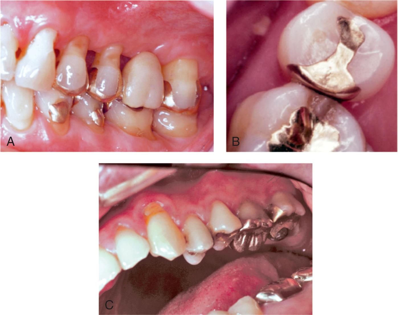
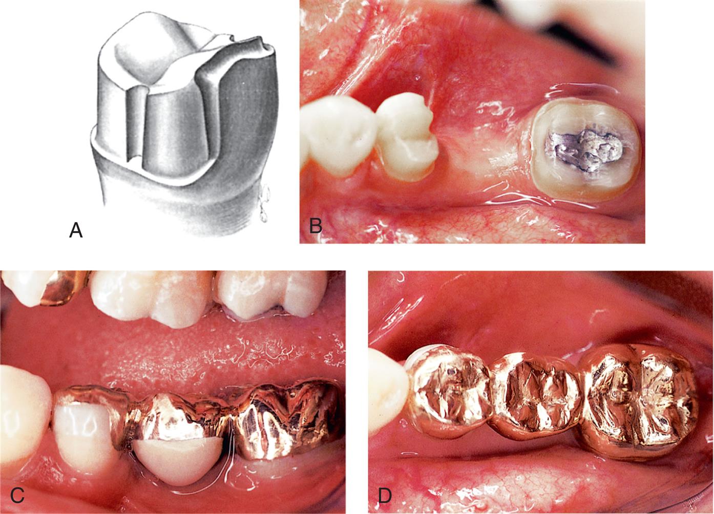
An extracoronal metal restoration that covers only part of the clinical crown is considered a partial veneer crown. It can also be referred to as a partial-coverage restoration. An intracoronal cast metal restoration is called an inlay, or an onlay if one or more cusps are restored. Examples of these restorations are presented in Fig. 11.1. Partial veneer crowns generally include all tooth surfaces except the buccal or labial wall in the preparation. Therefore these restorations preserve more of the tooth’s coronal tissue than does a complete crown. However, the preparation is more demanding and is not routinely provided by practitioners. Buccolingual displacement of the restoration is prevented by internal features (e.g., proximal boxes and grooves). Partial veneers can be used as single-tooth restorations or as retainers for a fixed partial denture (FPD). Although more often used on posterior teeth today, they can be used on both anterior and posterior teeth. Because they cover less of the coronal surface, partial coverage restorations tend to be less retentive than complete crowns and also less resistant to displacement. Inlays and onlays are even less retentive than partial veneer crowns. However, they provide the advantage of material strength (i.e., resistance to deformation) and preservation of tooth structure. Margins are generally more accessible, allowing improved finishing by the dentist, and cleaning by the patient. When carefully executed, inlays and onlays can be exceptionally long-lasting restorations (see Fig. 11.1).
Partial Veneer Crowns
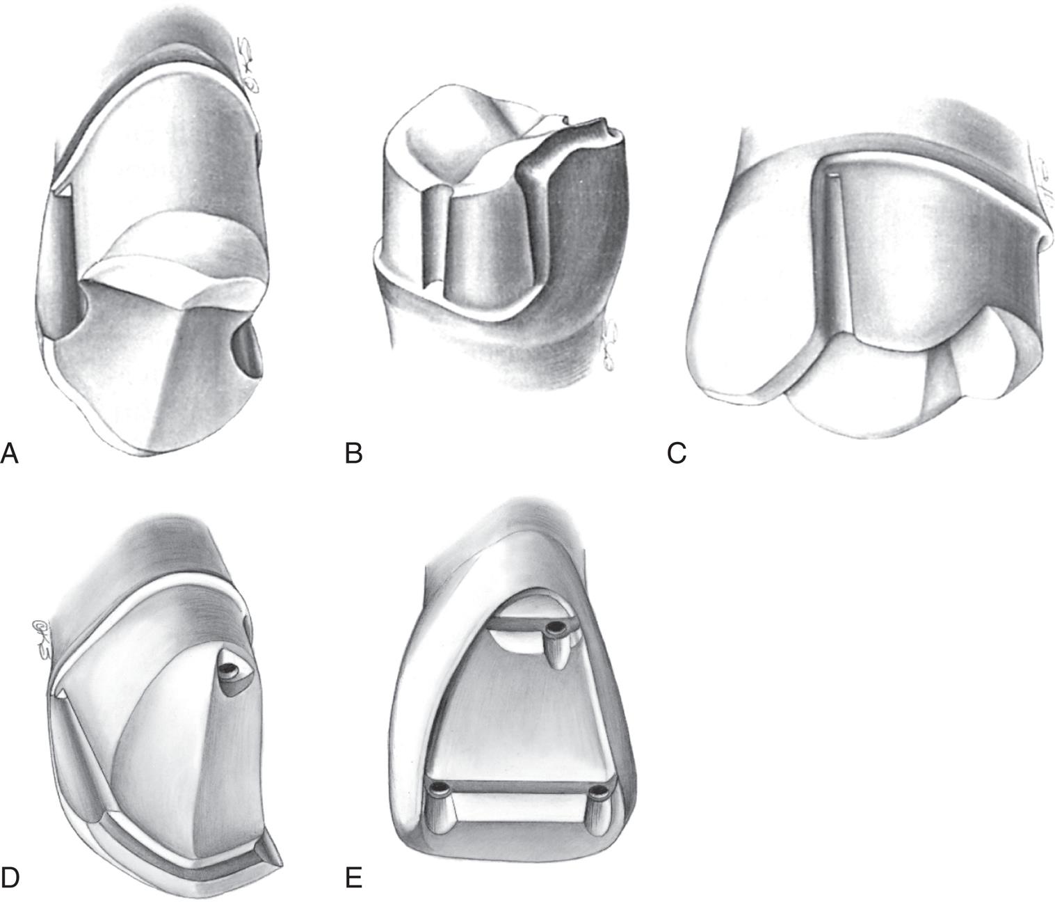
Over time, several types of cast partial veneer restorations have been used: for posterior teeth, these include three-quarter, modified three-quarter, and seven-eighths crowns; for anterior teeth, three-quarter crowns and pinledges (Fig. 11.2). In the presence of more esthetic contemporary materials cast partial veneer crowns are primarily used on posterior teeth, rather than in the esthetic zone.
Indications
Partial veneer crowns can be used to restore posterior teeth that have lost moderate amounts of tooth structure if the buccal wall of the abutment is intact and well supported by sound tooth structure. They provide adequate retention to be used as retainers for an FPD or where restoration or alteration of the occlusal surface is needed. Anterior cast partial veneers are rarely used today but can be used as retainers. They may offer a conservative approach to reestablish anterior guidance and can be used to splint teeth. They are particularly suitable for teeth with sufficient bulk since those can accommodate the necessary retentive features.
Contraindications
Partial veneer restorations are contraindicated on teeth with short clinical crowns because retention may be inadequate. They are also contraindicated as retainers for long-span FPDs. They are rarely suitable for endodontically treated teeth as insufficient tooth structure remains after the endodontic treatment to accommodate the retentive features. Often, on endodontically treated posterior teeth the buccal cusps are weakened by the access cavity. They are not suitable for teeth with extensively damaged crowns, and as is true of all cast restorations, partial veneer restorations are contraindicated in the presence of active caries or periodontal disease.
The shape and alignment of teeth are important determinants of the feasibility of partial veneer crowns. The alignment of axial surfaces should be evaluated carefully, and partial veneer crowns should not be prepared on teeth that are proximally bulbous. Making the necessary proximal grooves on such teeth will leave unsupported enamel. Similarly, it is often not possible to prepare adequate grooves on thin teeth with restricted faciolingual dimension.
Partial veneer crowns are usually prepared parallel to the long axis of the tooth, and poorly aligned abutment teeth are a contraindication since problems with unsupported enamel often result.
Advantages
The primary advantage associated with partial veneer crowns is conservation of tooth structure. Another advantage is reduced pulpal and periodontal insult during tooth preparation. Access to supragingival margins is rather easy, and the operator can perform selected finishing procedures that are more difficult or impossible with complete coverage restorations. Access is also better for oral hygiene. Because less of the margin approximates the soft tissues subgingivally, there is less gingival involvement than with complete crowns.
During cementation of a partial veneer, excess luting agent can escape more easily than during cementation of complete cast crowns, which facilitates seating of the restoration. Because of direct visibility, verification of seating and cement removal are simple. When the restoration is in service, the remaining intact facial or buccal tooth structure enables vitality testing.
Disadvantages
Partial veneer restorations have less retention and resistance than do complete cast crowns. Tooth preparation is more challenging because only limited adjustments can be made in the path of placement. The preparation of grooves, boxes, and pinholes requires dexterity of the operator. Some metal is displayed in the completed restoration, which may be unacceptable to patients.
Preparation
The teeth most commonly prepared for partial veneer restorations include maxillary and mandibular molars. Cast partial veneers are rarely applied anymore on anterior teeth because of the difficulty in achieving an esthetic result and have been replaced by ceramic alternatives. The technique illustrated is suitable for posterior teeth. Meticulous care and precision are required if partial veneer restorations are to be a successful (conservative) alternative to complete-coverage restorations.
Armamentarium
The necessary instruments for a partial veneer crown preparation include the following (Fig. 11.3):
- • Narrow (approximately 0.8 mm), round-ended, tapered diamond (regular or coarse grit)
- • Regular-size (approximately 1.2 mm), round-ended, tapered diamond (fine grit) or tungsten carbide bur
- • Football-shaped or wheel-shaped diamond (regular grit)
- • Tapered and straight tungsten carbide fissure burs
- • Small, round tungsten carbide bur
- • Small-diameter twist drill
- • Inverted-cone tungsten carbide bur
- • Finishing stones
- • Mirror
- • Explorer and periodontal probe
- • Chisels
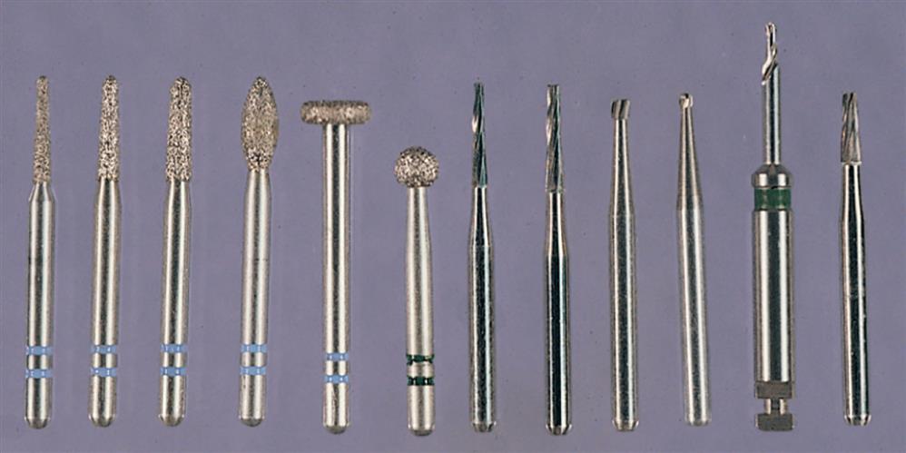
The regular- or coarse-grit diamonds are used for bulk reduction, and the fine-grit diamonds or tungsten carbide burs for finishing. If pinholes are required, they can be prepared with the twist drill and then shaped with a tapered tungsten carbide fissure bur. The tungsten carbide fissure burs are recommended for preparing boxes and ledges, and the inverted-cone tungsten carbide bur is useful for preparation of offsets. Hand instruments can be used to finish proximal flares and bevels. A periodontal probe is invaluable for assessing the alignment and dimension of the various preparation features.
Posterior Partial Veneer Crown Preparations
Maxillary Premolar Three-quarter Crown
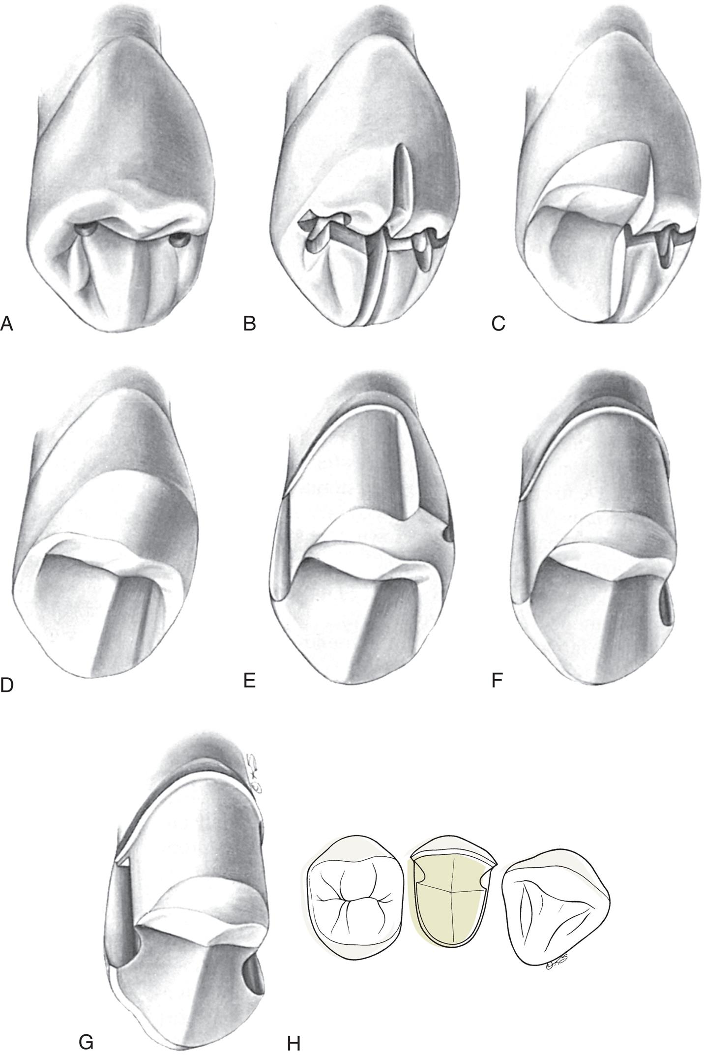
The step-by-step preparation of a three-quarter crown is illustrated on a maxillary premolar (Fig. 11.4). Except for a narrow bevel or chamfer margin placed along the bucco-occlusal line angle, the buccal surface of the abutment remains intact. The other surfaces (including the occlusal surface) are prepared to accommodate a casting in the same manner as a complete crown preparation (see Chapter 8), differing only in the need for proximal axial grooves to develop resistance form.
Occlusal reduction
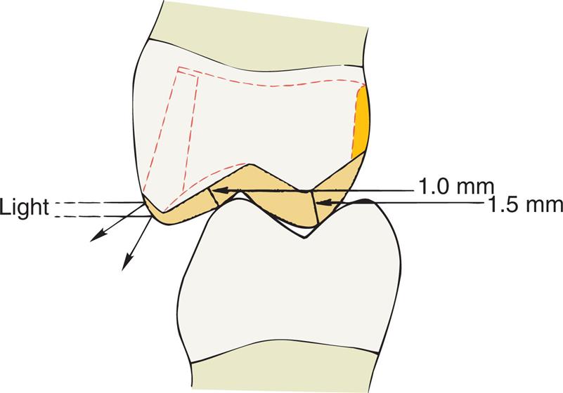
Upon the completion of occlusal reduction, the clearance on the functional cusp should be at least 1.5 mm, and those on the nonfunctional cusp and in the central groove should be at least 1.0 mm. Simultaneously, the tooth should be prepared so that metal display is minimal; the original outline form of the buccal wall should be preserved as well as possible.
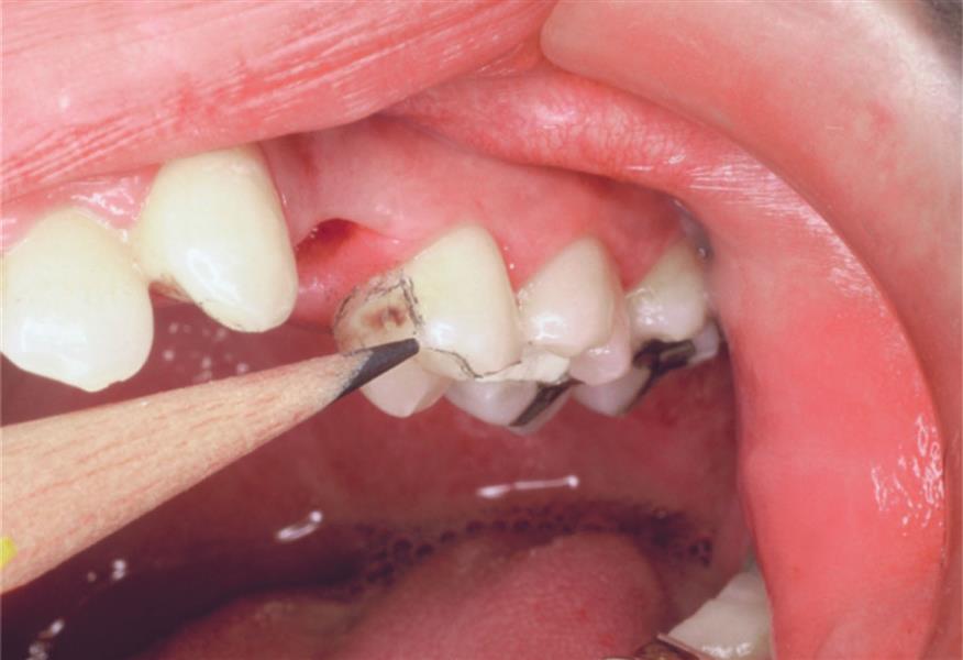
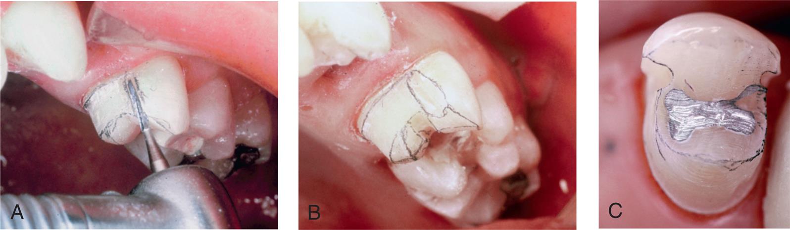
- 1. Before starting the preparation, mark the proposed margin location of the completed restoration on the tooth with a pencil (Fig. 11.5).
- 2. Place depth grooves for the occlusal reduction. These may be made with a tapered tungsten carbide bur or a narrow diamond in the developmental grooves of the mesial and distal fossae and on the crest of the triangular ridge. In the central groove, they should be kept slightly shallow to allow for finishing; similarly, on the functional (lingual) cusp, they should be slightly less than 1.5 mm deep in the location of the occlusal contacts.
- 3. Place three depth grooves on the lingual incline of the buccal cusp. Initially, these should be kept somewhat shallow as they approach the buccal cusp ridge (see Fig. 11.4B). In the area of occlusal contact, groove depth should accommodate at least 1 mm of clearance after finishing.
- 4. Verify groove depth with a periodontal probe. When acceptable, remove the islands of tooth structure remaining between the grooves (see Fig. 11.4C and D).
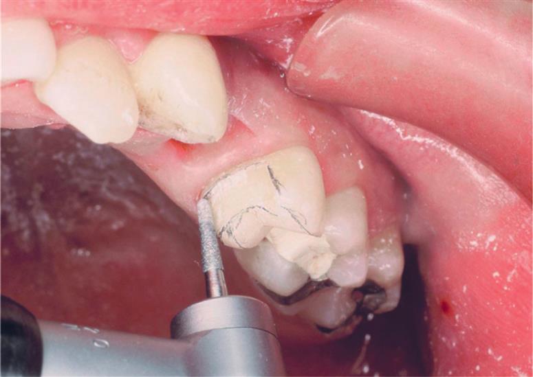
- 5. Assess the amount of occlusal clearance in maximum intercuspation (Fig. 11.6) and in all excursive movements of the mandible. Concave preparation of the lingual incline of the buccal cusp is helpful for obtaining sufficient clearance while maintaining the original occlusocervical dimension of the buccal tooth surface (Fig. 11.7).
Axial reduction
- 6. Depth grooves for axial alignment are prepared in the center of the lingual surface and in the mesiolingual and distolingual transitional line angles. These parallel the long axis of the tooth and should initially be kept shallow to avoid inadvertently creating a lip of unsupported enamel at the margin.
- 7. Because the path of placement of a partial veneer is critical, the orientation grooves must be critically evaluated when correction is still feasible. A common mistake is to angle the path of placement toward the buccal aspect. This reduces retention, leads to excessive display of metal, or both. A periodontal probe placed in each groove should be carefully viewed in both mesiodistal and buccolingual planes. It often helps to pour an irreversible hydrocolloid (alginate) impression in fast-setting plaster and to evaluate the cast with a dental surveyor; this is particularly useful if multiple partial veneers are being used as retainers for an FPD.
- 8. After alignment verification and, if necessary, correction, the tooth structure between the orientation grooves is removed with a smooth continuous motion, simultaneously with development of a cervical chamfer margin (Fig. 11.8).
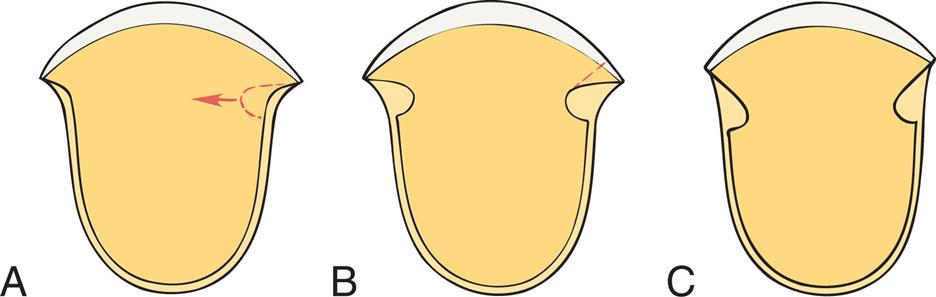
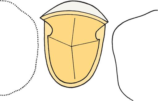
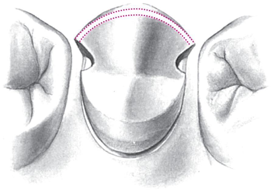
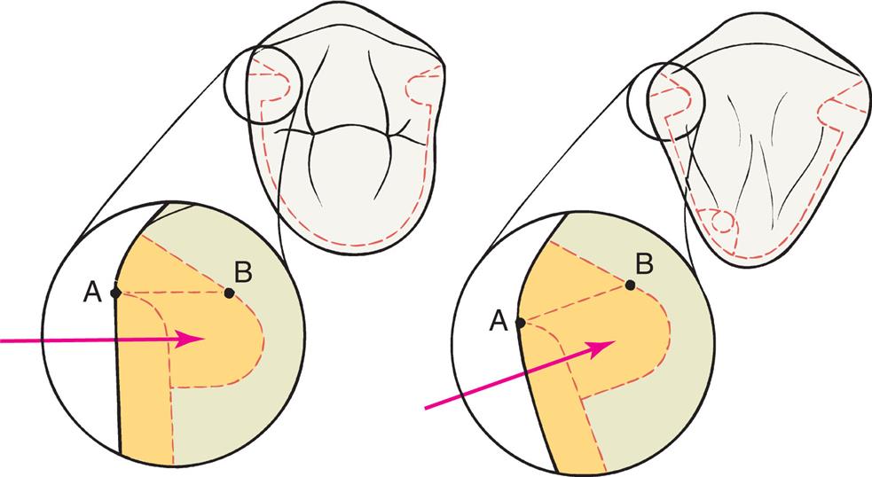
- 9. Carry the diamond into the proximal embrasure to reduce the proximal wall (see Fig. 11.4E and F). For proper extension of the proximal reduction of the axial tooth surface, it is critical to understand the factors that affect the correct position of the proximal groove. A proximal groove is placed parallel to the path of placement. Normally, unsupported tooth structure remains on the buccal side of the groove, and this side is flared to remove it. Fig. 11.9 illustrates the relationship among the initial axial reduction, groove placement, and location of the cavosurface angle where the flare meets the intact buccal wall. The cavosurface angle is especially significant when a tooth is prepared for a cast partial veneer that should display a minimum of metal; the farther to the buccal aspect the margin is, the more visible it will be. A subtle but important variable that affects the final location of the buccal margin is the apical extension of the preparation. As the cervical chamfer margin is placed closer to the cementoenamel junction, more axial tooth structure must be removed because of the normal anatomical shape of the abutment. Consequently, the deepest portion of the groove (its pulpal wall) is then located slightly closer to the mesiodistal center of the tooth. This results in a flare that will extend farther onto the facial or buccal surface than may be desirable. Marking the planned location of the intended facial flare on the tooth with a sterilized pencil before initiating the proximoaxial reduction is helpful. The intersection of this mark with the reduced proximal surface is a convenient reference point (see Fig. 11.5).
- 10. Stop the proximal reduction well short of the pencil mark and usually slightly short of breaking the proximal contact (Fig. 11.10). The resulting flange should parallel the linguoaxial preparation, with the chamfer margin placed sufficiently cervical to provide at least 0.6 mm of clearance with the adjacent tooth and adequate axial wall height, to permit subsequent placement of a proximal groove that is at least 4 mm long occlusocervically (see Fig. 11.4F and G).
Groove placement
The proximal grooves are best prepared with a tapered tungsten carbide bur.
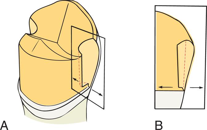
- 11. Position the bur against the interproximal flange parallel to the path of placement and make a groove perpendicular to the axial surface. The groove need not be deeper than 1 mm at its cervical end but may be deeper near its occlusal end (Fig. 11.11). During this stage, the bur must be held precisely parallel to the selected path of placement. Allowing it to tip axially results in excessive taper between opposing proximal grooves, a common error. The criteria that need to be met consist of the following:
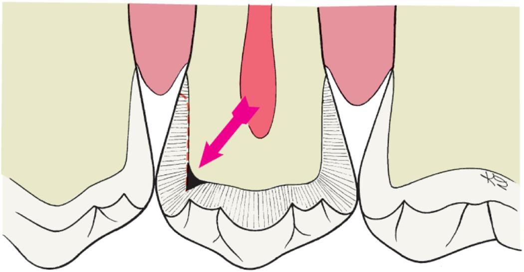
- • The grooves should resist lingual displacement of a periodontal probe or explorer (Fig. 11.12).
- • The walls of the grooves should not be undercut in relation to the selected path of placement.
- • The walls should be flared toward the intact buccal surface of the tooth (see Fig. 11.4G and H).
Depending on available access, it may be feasible to complete the flaring with the same rotary instrument that was used to place the groove (Fig. 11.13). However, removing the last “lip” of unsupported tooth structure with a chisel is often a better option because this minimizes the risk of damage to the adjacent tooth.
Bucco-occlusal contrabevel
- 12. Connect the mesial and distal flares with a narrow contrabevel that follows the buccal cusp ridges. This can be placed with a diamond, a tungsten carbide bur, or even a hand instrument. Its primary purpose is to remove any unsupported enamel and thereby protect the buccal cusp tip from chipping during function. If group function is planned (as opposed to a mutually protected occlusion), a heavier bevel, a chamfer margin, or an occlusal offset is needed because tooth contact occurs in this area during excursive movement. The bevel should remain within the curvature of the cusp tip, rather than extend onto the buccal wall (Fig. 11.14). This results in a convex shape of the restoration, and light is prevented from reflecting back to a casual observer (see Fig. 11.7). Thus the restoration is less obvious, and the outline form of remaining buccal enamel is perceived as the shape of the tooth.
Finishing
- 13. With the exception of the junction between grooves and proximal walls, round all sharp internal line angles to facilitate subsequent procedures. A fine-grit diamond or tungsten carbide bur can be used to blend the surfaces (Fig. 11.15).
- 14. Reevaluate the flares, paying particular attention to any remaining undercuts, which must be removed. The flares should be monoplane, straight, and smooth, with sufficient clearance between them and the adjacent tooth. A minimum clearance of 0.6 mm is recommended. The mesial flare cannot extend beyond the transitional line angle. However, because the distal margin is less visible, it may extend slightly farther to the buccal margin, allowing easier access (Fig. 11.16). Fig. 11.17 shows the step-by-step sequence of a three-quarter cast partial veneer crown on a maxillary molar.


Examples of Other Cast Partial Veneer Crowns
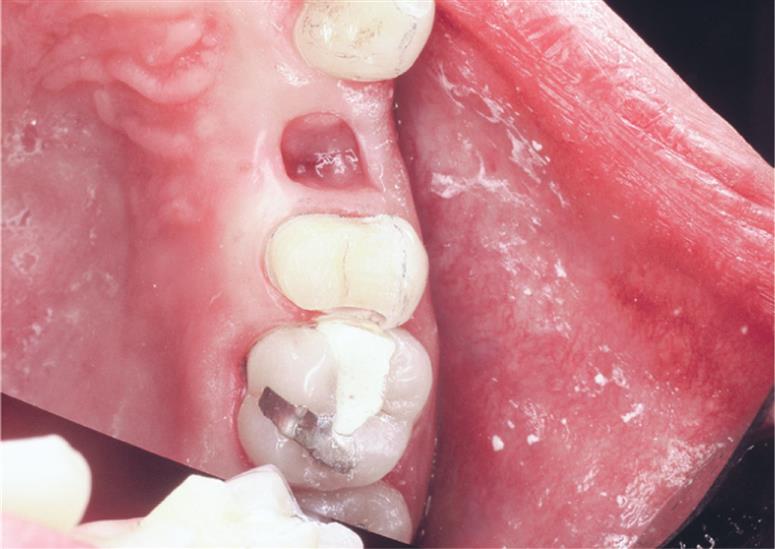
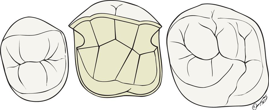
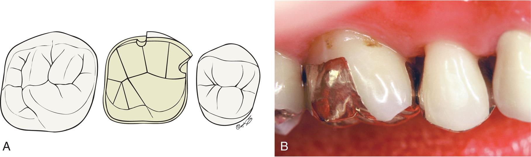
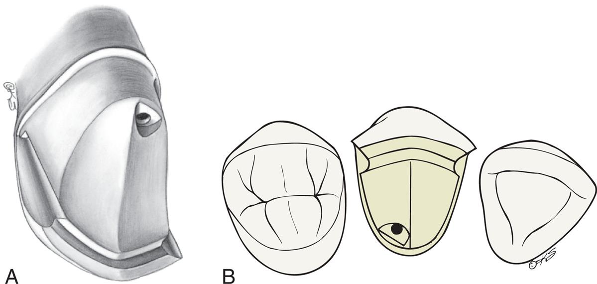
Although largely surpassed in popularity by adhesively bonded ceramic restorations—at least for restoration of single teeth—a few clinical examples of other types of cast partial veneer crowns are illustrated to help understand the geometry of their preparation designs and since they still may be encountered clinically. Fig. 11.18 shows the design of a seven-eighths crown on a maxillary molar and a clinical example. A modified three-quarter crown used as a retainer for a three-unit FPD is illustrated in Fig. 11.19.
With the advent of metal-ceramic and ceramic restorations, the use of partial veneer restorations on anterior teeth has become rare. Nevertheless, two anterior partial veneer crown preparations, the maxillary canine three-quarter crown and the pinledge, are worthy of study. Few preparations are as technically demanding as the three-quarter crown preparation on a maxillary canine (Fig. 11.20) which stems from the proximal curvature that this tooth exhibits. This challenge is illustrated in Fig. 11.21. A clinical example is shown in Fig. 11.22.
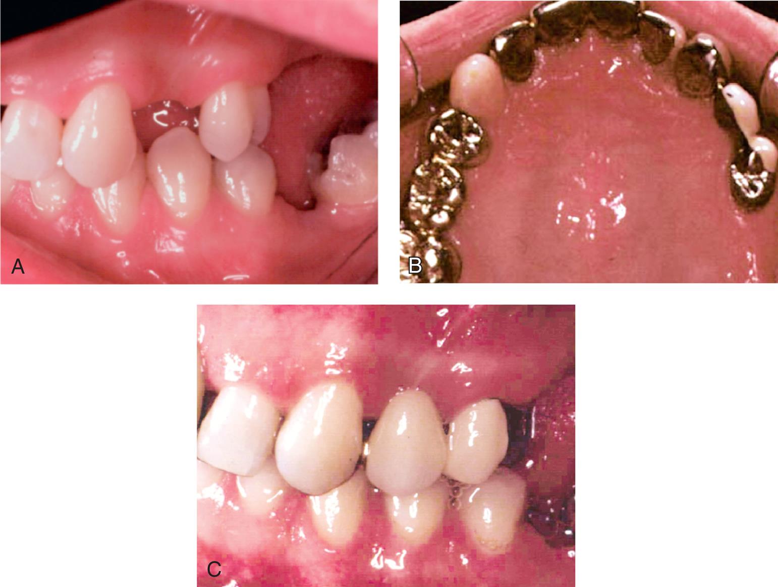
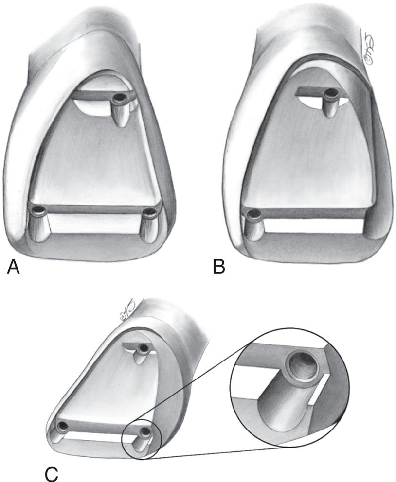
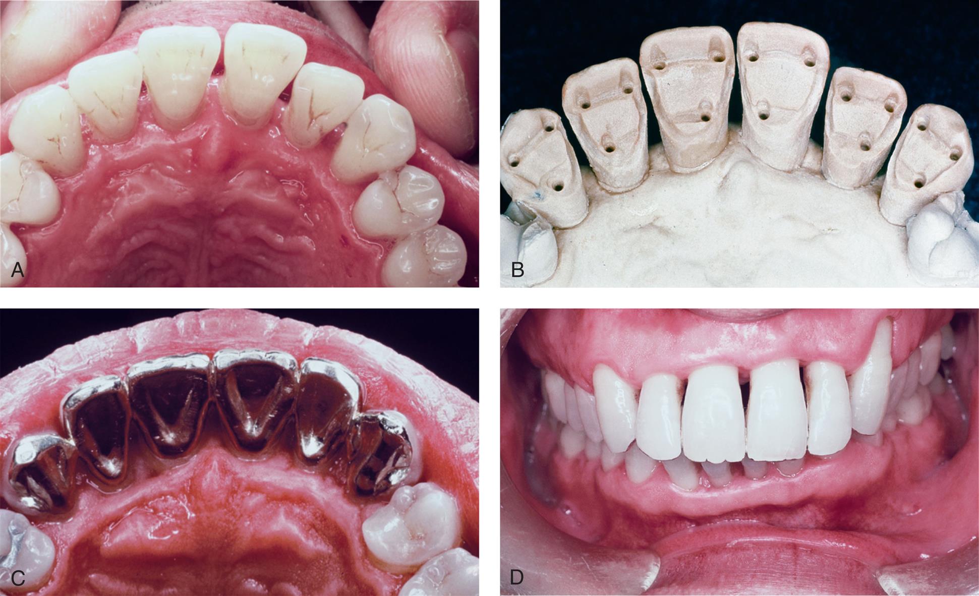
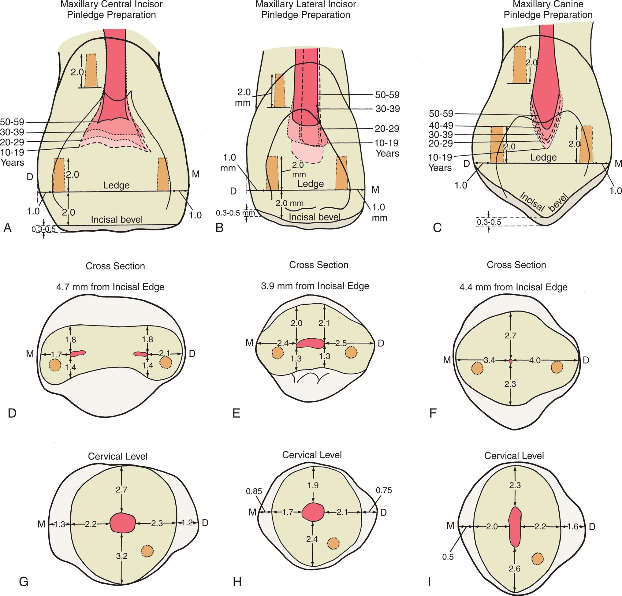
Although always considered technically challenging, pinledge preparations (Fig. 11.23) were used on intact anterior teeth and encompassed minimal tooth reduction while providing adequate mechanical support for short-span FPDs or splints (Fig. 11.24). They are of interest because their clinical application enhanced our understanding of optimal placement of pinholes in anterior teeth (Fig. 11.25).
Inlays and Onlays
Indications
An inlay can be used instead of amalgam for patients with a low caries rate who require a small interproximal restoration in a tooth with ample supporting dentin. It is among the least complicated cast restorations to make and can be very durable when done carefully. An onlay allows a damaged occlusal surface to be restored with a casting in the most conservative manner. It should be considered in the restoration of a severely worn dentition when the teeth are otherwise minimally damaged or for the replacement of a mesio-occlusal–distal (MOD) amalgam restoration when sufficient tooth structure remains for retention and resistance form.
Contraindications
Because these restorations rely on intracoronal (wedging) retention, inlays and onlays are contraindicated unless there is sufficient bulk to provide resistance and retention form. MOD inlays may increase the risk of cusp fracture and are generally not recommended. Extensive onlays, required where caries or existing restorations extend beyond the facial or lingual line angles, are contraindicated unless pins are used to supplement retention and resistance.
Advantages
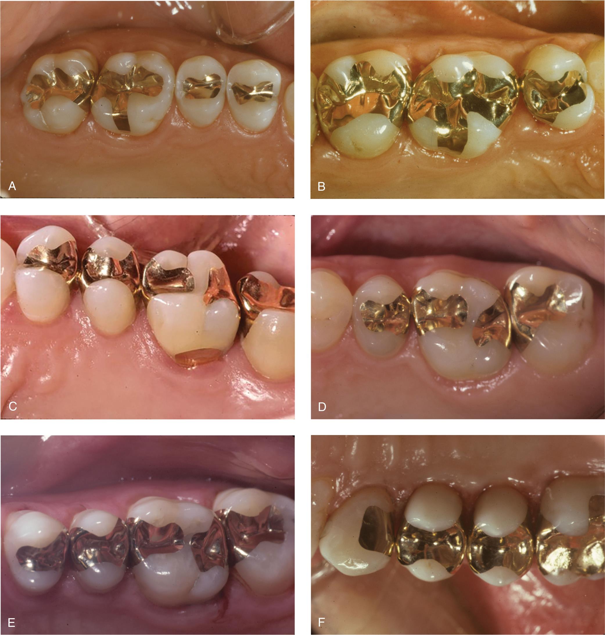
Cast inlays and onlays can be extremely long-lived restorations because of the excellent mechanical properties of the gold alloy (see Fig. 11.1). Low creep and corrosion mean that if inlay or onlay margins are accurately cast and finished, they will not deteriorate. The lack of corrosion may also offer an esthetic advantage. Gold does not lead to the tooth discoloration sometimes associated with dental amalgam. Unlike an inlay or amalgam, an onlay can support cusps, reducing the risk of tooth fracture.
Disadvantages
In the restoration of a small carious lesion, an inlay is not very conservative of tooth structure. This is because additional tooth removal is necessary after minimal proximal extension to achieve a cavity preparation without undercuts and to enable access for impression making. This extension may lead to additional display of metal and to gingival encroachment, which is undesirable for periodontal health. Because inlays do not encircle the tooth, the bulk of the buccal and lingual cusps must provide resistance and retention form. Of concern is that high occlusal force may lead to cusp fracture as a result of wedging from the inlay.
Preparation
Armamentarium
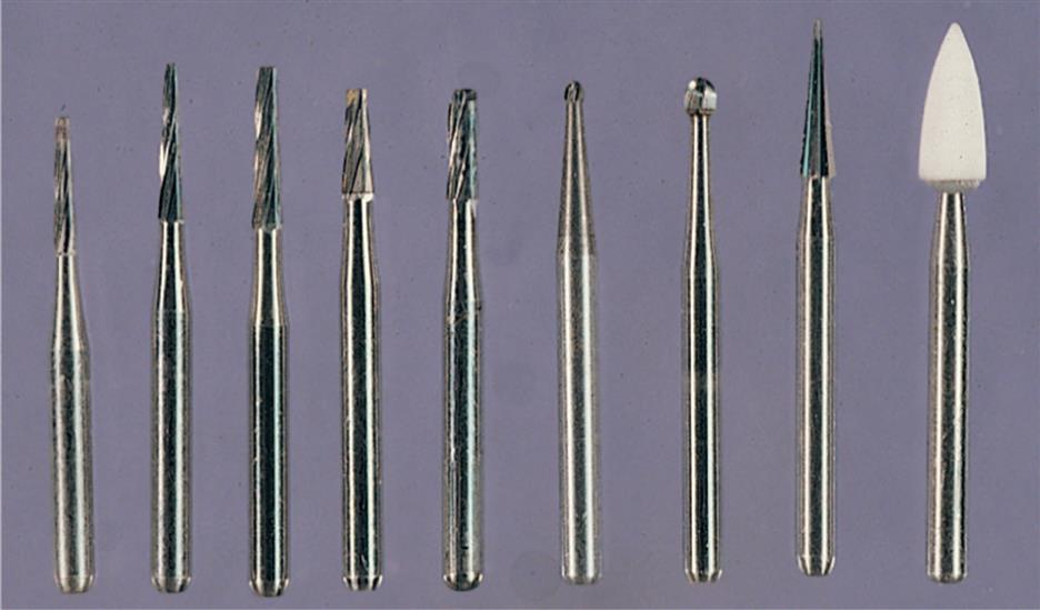
Tungsten carbide burs are usually used for inlay or onlay preparations (Fig. 11.26), but diamonds can be substituted if preferred:
Mesio-occlusal or Distal-occlusal Inlay Preparation
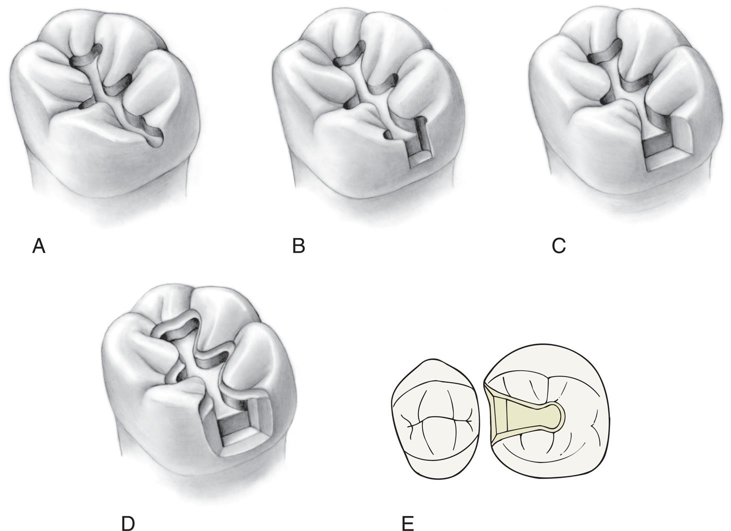
The MO or DO inlay preparation follows a series of steps (Fig. 11.27).
Occlusal Analysis
- 1. Carefully assess the occlusal contact relationship and mark it with articulating film. The margins of the restoration should not be too close (≥1.0 mm) to a centric contact; otherwise, there will be damaging stresses at the gold-enamel junction.
- 2. Apply rubber dam. Because good visibility and moisture control are essential during tooth preparation and caries excavation, the use of a rubber dam is strongly recommended.
Outline Form
- 3. Penetrate the central groove just to the depth of the dentin (typically about 1.8 mm) with a small round or tapered tungsten carbide bur held in the path of placement of the inlay. In general, this is perpendicular to an imaginary line connecting the buccal and lingual cusps, not necessarily perpendicular to the occlusal plane. For example, on mandibular premolars, it is angled toward the lingual aspect.
- 4. Extend the occlusal outline through the central groove with the tapered tungsten carbide bur. The bur should be held in the same path of placement and kept at the same depth: just into dentin. The buccolingual extension should be as conservative as possible to preserve the bulk of the buccal and lingual cusps. Resistance to proximal displacement is achieved with a small occlusal dovetail or pinhole. The outline should avoid the occlusal contacts.
- 5. Extend the outline proximally, undermining the marginal ridge, and stop it at the height of contour of the ridge (Fig. 11.28A).
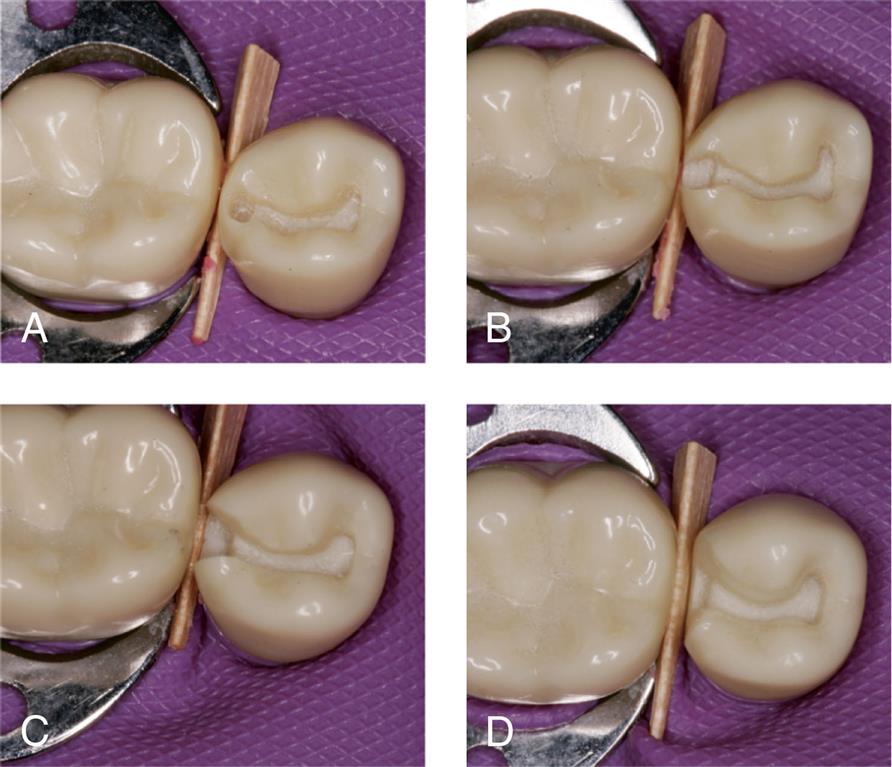
- 6. Advance the bur cervically to the carious lesion and then lingually and buccally, taking care to hold it in the precise path of placement. A thin layer of enamel should remain between the side of the bur and the adjacent tooth (see Fig. 11.28B). This prevents accidental damage. The bur should move parallel to the original unprepared proximal surface, creating a convex axial wall in the interproximal preparation or box. The opposing buccal and lingual walls contribute significantly to retention; therefore, great care must be taken not to tilt the bur during this step. It should be held in the path of placement throughout. The width of the gingival floor of the box should be about 1.0 mm (mesiodistally). Correct cervical, lingual, and buccal extension at this stage is just beyond the proximal contact area. The completed inlay will require a minimum proximal clearance of 0.6 mm to allow an impression to be made, but some of this will be achieved with the proximal flares and gingival bevels. Sharp line angles between the occlusal outline and proximal box are rounded at this time (see Fig. 11.28C).
Caries Excavation
- 7. Identify and remove any caries not eliminated by the proximal box preparation, with the use of an excavator or a round bur in the low-speed handpiece.
- 8. Place a cement base to restore the excavated tissue in the axial wall, pulpal floor, or both. If necessary, the preparation can be extended buccally or lingually. An inlay is not a suitable restoration for extensive caries and carrying it beyond the line angles will lead to a significant loss of retention and resistance form.
Axiogingival Groove and Bevel Placement
- 9. Prepare a small, well-defined groove at the junction of the axial and gingival walls at the base of the proximal box to enhance resistance form and prevent distortion of the wax pattern during manipulation. It is easily placed with a gingival margin trimmer held in contact with the axial wall to prevent creating an undercut.
- 10. Place a 45-degree gingival margin bevel with a thin, tapered tungsten carbide bur or a fine-grit diamond. Correct orientation is achieved by holding the instrument parallel to the gingival third of the proximal surface of the adjacent tooth. The bur should not be tilted buccally or lingually to the path of placement; otherwise, an undercut will be created at the corners of the box (a common error in inlay preparations).
- 11. Prepare proximal bevels on the buccal and lingual walls with the tapered bur oriented in the path of placement. There should be a smooth transition between the proximal and gingival bevels.
- 12. Place an occlusal bevel to improve marginal fit and allow finishing of the restoration. When the cuspal anatomy is steep, a conventional straight bevel produces too little metal near the margin for strength and durability. A hollow-ground bevel or chamfer margin is normally preferred and can be conveniently placed with a round bur or stone.
- 13. As a final step, smooth the preparation where necessary, paying particular attention to the margin (see Fig. 11.28D).
Fig. 11.29 shows some outstanding clinical examples of conservative cast inlays.
Mesio-occlusal–distal Onlay Preparation
The occlusal outline and proximal boxes of an onlay preparation (Fig. 11.30) are similar to those of an inlay. The additional steps are the occlusal reduction and a functional (centric) cusp ledge.
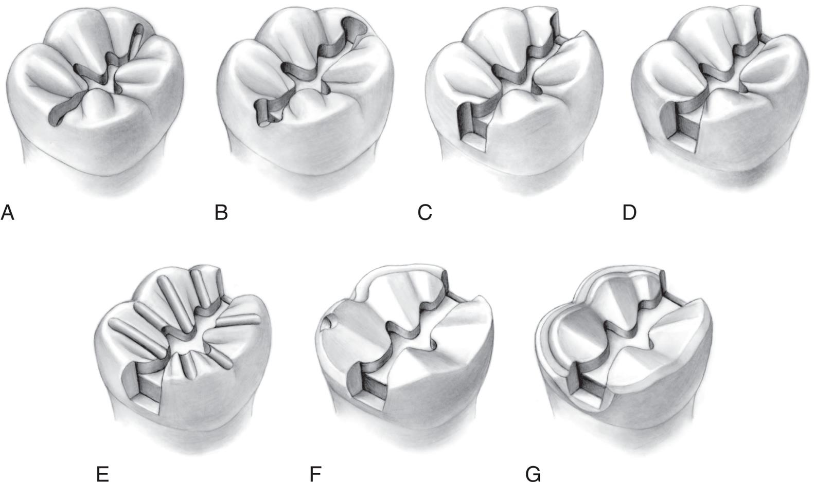
Outline Form
- 1. Prepare the occlusal outline with a tapered tungsten carbide bur just beyond the enamel-dentin junction (approximately 1.8 mm deep) and extend it through the central groove, incorporating any deep buccal or lingual grooves. Existing amalgam restorations are removed as part of this step (Fig. 11.31A).
- 2. Extend the outline both mesially and distally to the height of contour of the marginal ridge. As with an inlay, prepare the boxes with an MOD onlay by advancing the bur gingivally and then buccally and lingually, always holding it in the precise path of placement of the preparation. If a thin section of proximal enamel remains as the bur advances, damage to the adjacent tooth will be prevented (see Fig. 11.31B). Correct gingival, buccal, and lingual extension of the preparation normally depends on the contact area with the adjacent tooth. A minimum clearance of 0.6 mm is needed for impression making. Sometimes existing restorations or caries necessitate that a box be extended beyond optimal. However, if a box requires extension beyond the transitional line angle, the preparation will have little resistance form, and an alternative restoration, such as a complete crown, should be considered. Preparing the boxes is a key step when an onlay is fabricated (see Fig. 11. 31C and D). The tapered bur should be held precisely in the planned path of placement throughout. Tilting, often caused by attempts to advance the bur too quickly, is common and is difficult to correct.
- 3. Round sharp line angles between the occlusal outline and proximal boxes.
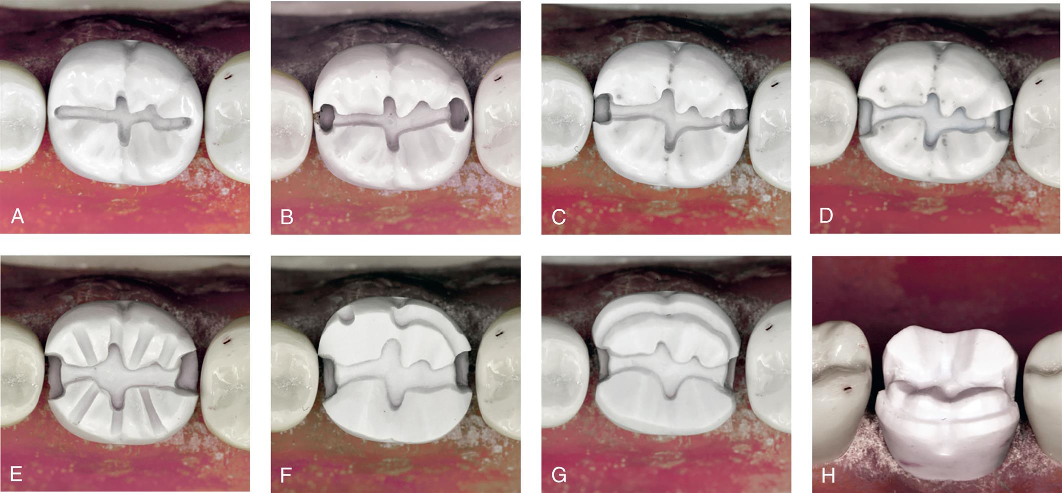
Caries Excavation
Occlusal Reduction
- 6. Place depth grooves on the functional cusps. To provide additional clearance at the cusp tip, the bur must be oriented more horizontally than the intended restoration cusp. The grooves should be 1.3 mm deep, allowing 0.2 mm for smoothing (see Fig. 11.31E).
- 7. Place 0.8-mm grooves on the nonfunctional cusps. The bur is oriented parallel to the cuspal inclines. As with all depth grooves, it is assumed that the tooth is in good occlusal relation before preparation. If it is not, a vacuum-formed matrix made from the diagnostic waxing procedure is recommended as a guide.
- 8. Connect the grooves to form the occlusal reduction, maintaining the general contour of the original anatomy.
- 9. Prepare a 1.0-mm functional cusp ledge with the cylindrical tungsten carbide bur (see Fig. 11.31F). This provides the restoration bulk in a high-stress area, preventing deformation during function. The ledge should be placed about 1 mm apical to the opposing centric contacts. It extends into the proximal boxes but should not be positioned too far apically; otherwise, the resistance form from the boxes will be lost.
- 10. Round any sharp line angles, particularly at the junction of the ledge and occlusal surface.
- 11. Check for adequate occlusal reduction by having the patient close the jaws into soft wax and measuring with a thickness gauge.
Margin Placement
- 12. Establish a smooth, continuous bevel on all margins. The gingival bevel is placed, as for an inlay, with the thin tungsten carbide bur or diamond held at a 45-degree angle to the path of placement, or approximately parallel to the adjacent tooth contour. This will blend smoothly with the buccal and lingual bevels, which have been prepared with the bur held in the path of placement.
- 13. Bevel the nonfunctional and functional cusps. Where additional bulk at the margin is needed, a chamfer margin should be substituted for the straight bevel margin. This can be placed with a round-ended diamond.
- 14. Complete the preparation by rechecking the occlusal clearance in all excursions and assessing for smoothness (see Fig. 11.31G and H).
Clinical examples of onlay restorations are shown in Fig. 11.32.

Study Questions
- 1. What are the indications for and contraindications to partial veneer crowns?
- 2. What are the advantages and disadvantages of partial veneer crowns?
- 3. What is the recommended armamentarium, and in what sequence should a maxillary premolar be prepared, for a partial veneer crown?
- 4. What are the minimal criteria for each step just described?
- 5. What are the indications for and contraindications to inlay/onlay restorations?
- 6. What are the advantages and disadvantages of inlay/onlay restorations?
- 7. What is the recommended armamentarium, and in what sequence should a mandibular molar be prepared, for an inlay/onlay restoration?
- 8. What are the minimal criteria for steps 5, 6, and 7? Why?