Connectors for Fixed Partial Dentures
Abstract
Connectors join individual retainers and pontics. Rigid or nonrigid connectors can be used. Connector size, shape, and position influence the success of a partial FDP. The use of soldered connectors can simplify the fabrication of larger FDPs, which may be cast separately in groups of one or two units and assembled after their individual fit has been verified. The technical procedures involved in soldering are not difficult.
Keywords
Rigid Connectors; Non-rigid connectors; Connector design; Soldered connectors; Cast connectors; Laser Welding
Connectors are the components of a fixed partial denture (FPD) or splint that join the individual retainers and pontics together. Usually this is accomplished with rigid connectors (Fig. 27.1), although nonrigid connectors are occasionally used. The latter are usually indicated when it is impossible to prepare a common path of placement for the abutment preparations for an FPD (Fig. 27.2A and B). Their use has been reported to be associated with significantly reduced failure rates.1
Rigid Connectors
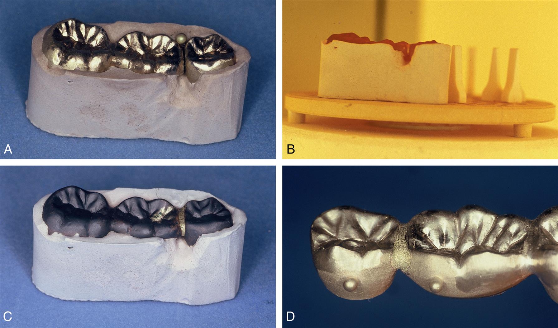
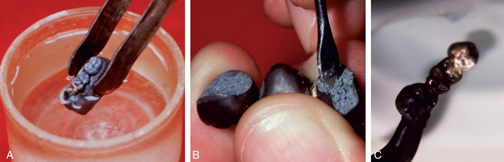
Rigid connections in metal can be made by casting, milling, laser sintering, soldering, or welding. Cast connectors are shaped in wax as part of a multiunit wax pattern. Milled or laser-sintered connectors are shaped in the computer processing when computer-aided design and computer-aided manufacturing (CAD-CAM) is used.2 Cast connectors are convenient and minimize the number of steps involved in the laboratory fabrication. However, the fit of the individual retainers may be adversely affected because distortion more easily results when a multiunit wax pattern is removed from the die system. Soldered connectors involve the use of an intermediate metal alloy whose melting temperature is lower than that of the parent metal (Fig. 27.3). The parts being joined are not melted during soldering but must be thoroughly wettable by liquefied solder.3 Dirt or surface oxides on the connector surfaces can interfere with wetting and impede successful soldering; for example, the solder may melt but does not flow into the soldering gap. Welding is another method of rigidly joining metal parts. In welding, the connection is created by melting adjacent surfaces that are often in contact with each other, with heat or pressure. A filler metal whose melting temperature is about the same as that of the parent metal can be used in welding.
In industrial metalworking, a distinction is made between soldering, in which the filler metal has a melting point below 450°C (842 °F), and brazing, in which the filler has a melting point above 450°C.4 Rigid connections in dentistry are generally fabricated at temperatures above 450°C, but the process has almost always been referred to in the dental literature as soldering. However, in a proposed international standard, the term brazing is used. With time, the latter term may become more generally accepted. In this text, however, the term soldering is used.
Nonrigid Connectors
Nonrigid connectors are indicated when it is not possible to prepare two abutments for an FPD with a common path of placement. Segmenting the design of large, complex FPDs into shorter components that are easier to replace or repair individually is advisable. This can be helpful if an abutment's prognosis is uncertain. If the abutment fails, only a portion of the FPD may need to be remade. In the mandibular arch, nonrigid connectors are indicated when a complex FPD consists of anterior and posterior segments. During the mandibular opening and closing stroke, the mandible flexes mediolaterally.5,6 Rigid FPDs have been shown to inhibit mandibular flexure, and extensive splints have been shown to flex during forced opening.7,8 The associated stresses can cause dislodgment of complex FPDs. Segmenting complex mandibular FPDs can minimize this risk (Fig. 27.4).
Nonrigid connectors are generated through incorporation of prefabricated inserts in the wax pattern or through custom milling procedures after the first casting has been obtained. The second part is then custom fitted to the milled retainer and cast. They are often made with prefabricated plastic patterns. The retainers are then cast separately and fitted to each other in metal.
Connector Design
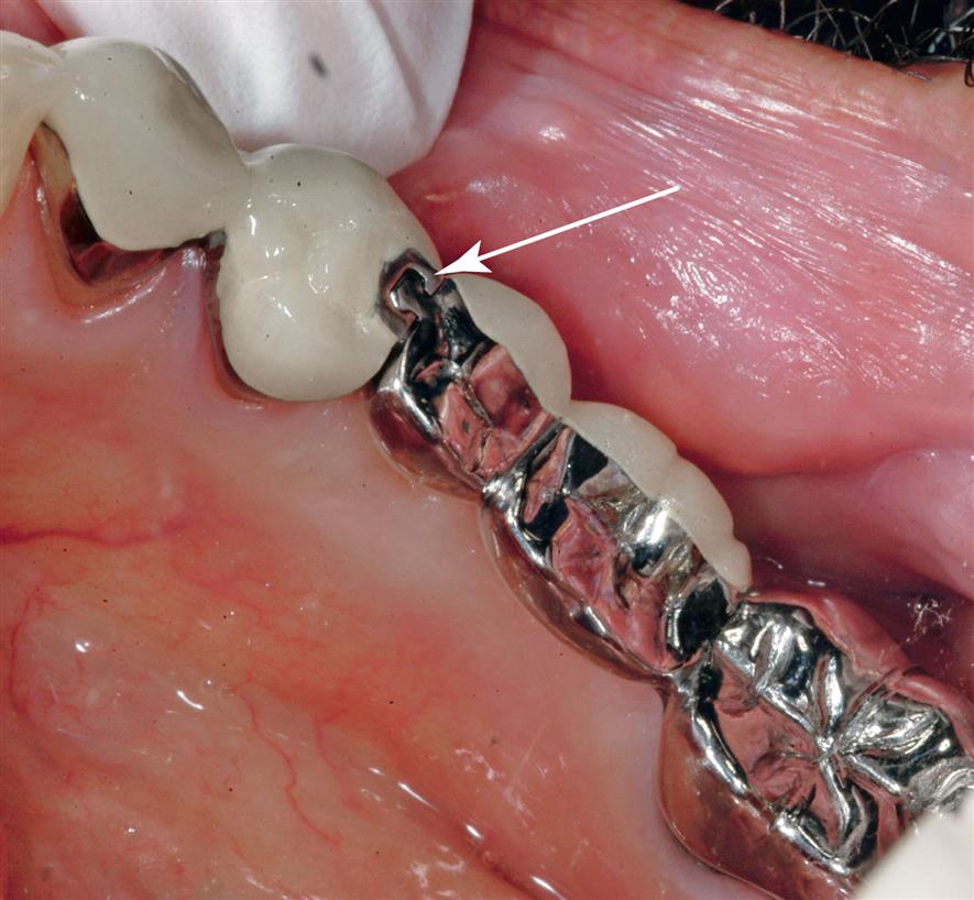
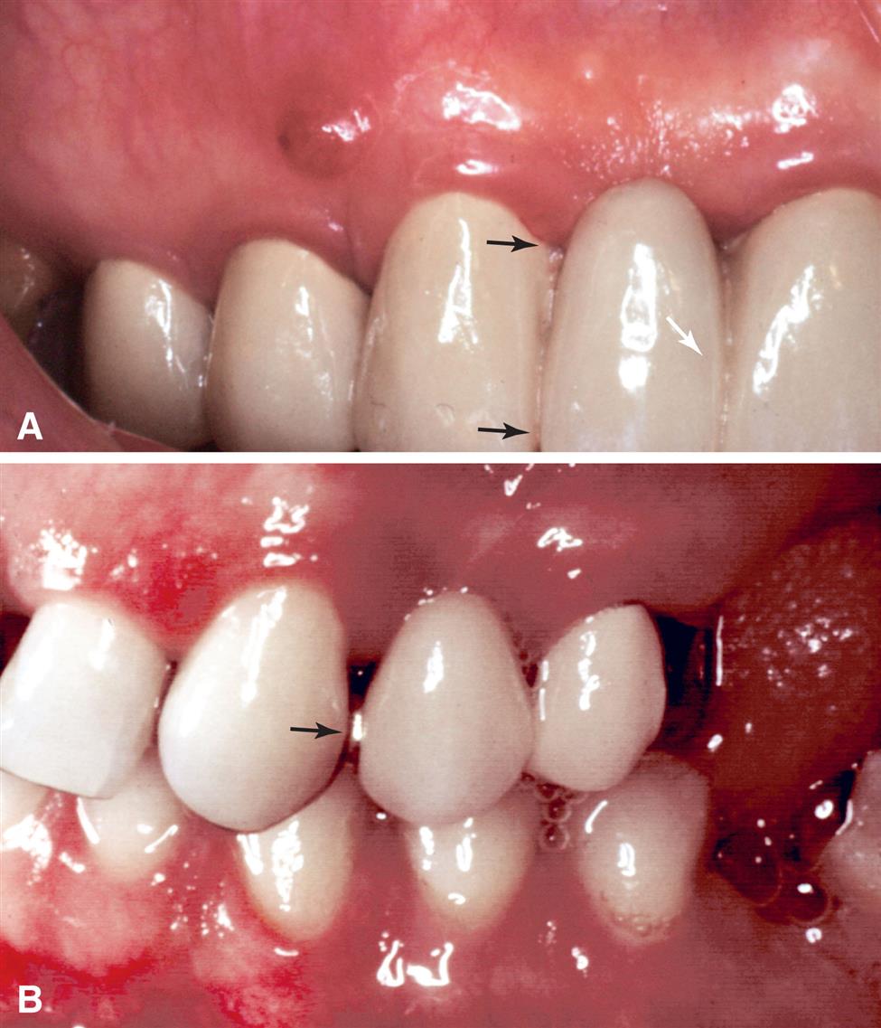
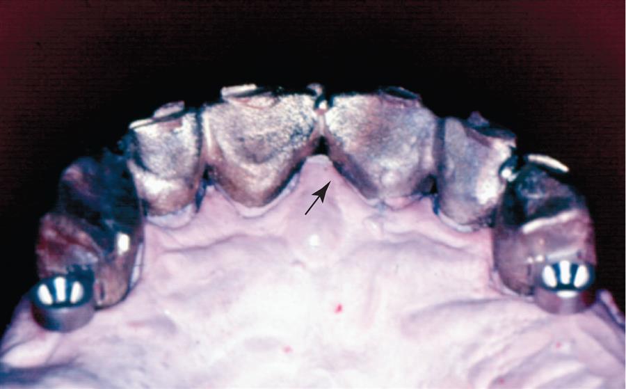
The size, shape, and position of connectors all influence the success of the prosthesis. Connectors must be sufficiently large to prevent distortion or fracture during function but not too large; otherwise, they interfere with effective plaque control and contribute to periodontal breakdown over time. Adequate access (i.e., embrasure space) must be available for oral hygiene aids cervical to the connector. If a connector is too large incisocervically, hygiene is impeded, and over time, periodontal failure will result (Fig. 27.5A). For esthetic FPDs, a large connector or inappropriate shaping of the individual retainers may result in display of the metal connector, which may compromise the appearance of the restoration and cause patient dissatisfaction (see Fig. 27.5B).
In addition to being highly polished, the tissue surface of connectors is curved faciolingually to facilitate cleaning. Mesiodistally, it is shaped to create a smooth transition from one FPD component to the next. A properly shaped connector has a configuration similar to a meniscus formed between the two parts of the prosthesis.
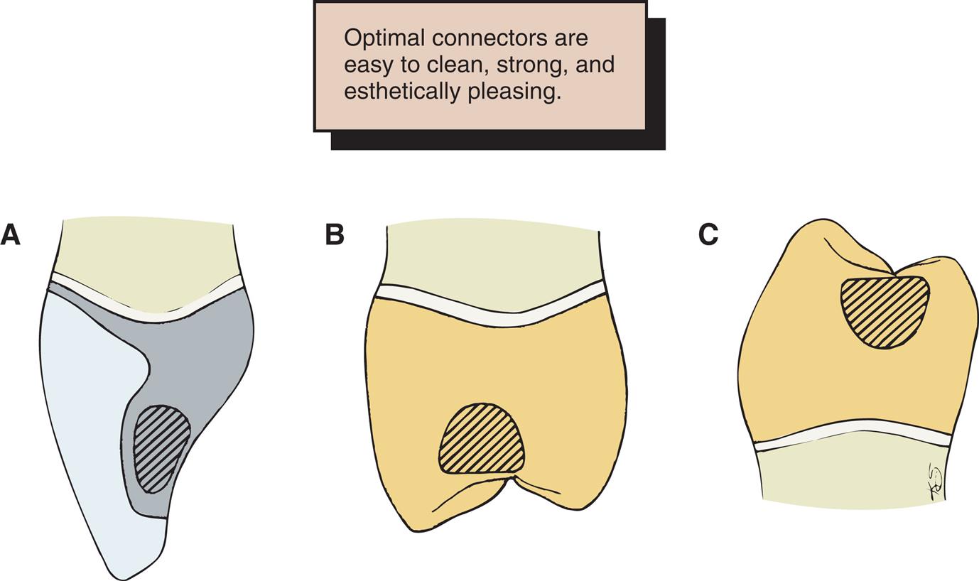
In a buccolingual cross section, most connectors are somewhat elliptical. Elliptical connectors are strongest if the major axis of the ellipse parallels the direction of the applied force. Unfortunately, because of anatomic considerations, this cannot always be achieved. In fact, because of space constraints, the greatest dimension of most connectors is perpendicular to the direction of applied force, which tends to weaken the connectors. For ease of plaque control, the connectors should occupy the normal anatomic interproximal contact areas because encroaching on the buccal, gingival, or lingual embrasure restricts access. However, to improve appearance without significantly affecting plaque control, anterior connectors are normally placed toward the lingual embrasure. Fig. 27.6 depicts typical locations for connectors on selected teeth.
Pulp size and clinical crown height can be limiting factors in the design of nonrigid connectors. Most prefabricated patterns require the preparation of a fairly sizable box. This allows incorporation of the mortise (see the section Nonrigid Connectors and Fig. 27.8) in the cast restoration without overcontouring of the interproximal emergence profile. Short clinical crowns do not provide adequate occlusocervical space to ensure adequate strength. Most manufacturers recommend 3 to 4 mm of vertical height, which is supported by empirical clinical findings.

Types of Connectors
Rigid Connectors
Rigid connectors must be shaped and incorporated into the wax pattern after the individual retainers and pontics have been completed to definitive contour but before reflowing of the margins for investing (see Chapter 18). When a CAD-CAM process is used, the connectors are designed as part of the framework with the computer software program.2
Cast Connectors
Connectors to be cast are also waxed on the definitive cast before reflowing and investing of the pattern. The presence of a cast connector makes the process of investing somewhat more awkward: Access to the proximal margin is impeded, and the pattern cannot be held proximally during removal from the die. Restricting cast connectors to complete coverage restorations, which can be gripped buccolingually, is therefore advisable. Partial-coverage wax patterns are easily distorted, particularly when they are part of a single-cast FPD. One-piece castings often appear to simplify fabrication but tend to create more problems than do soldered connectors, especially as pattern complexity increases.
Soldered Connectors
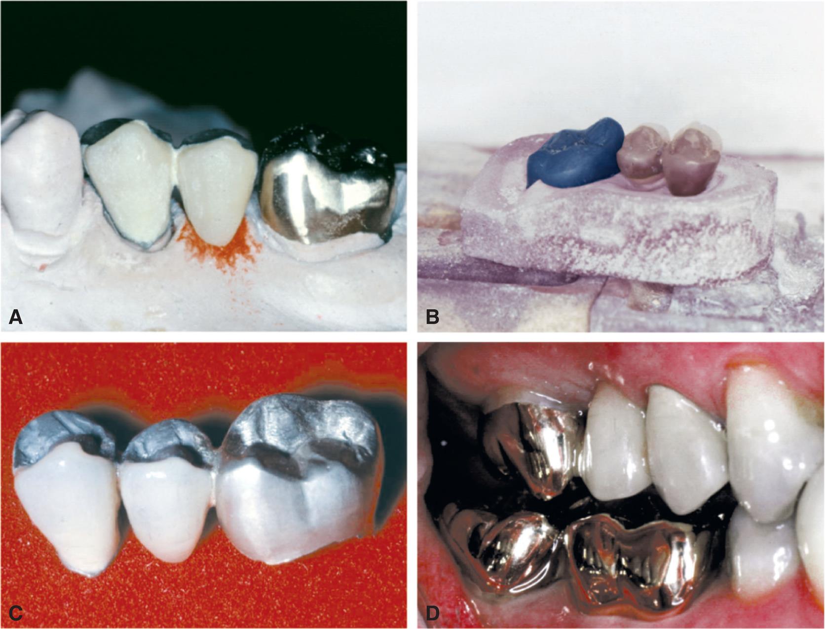
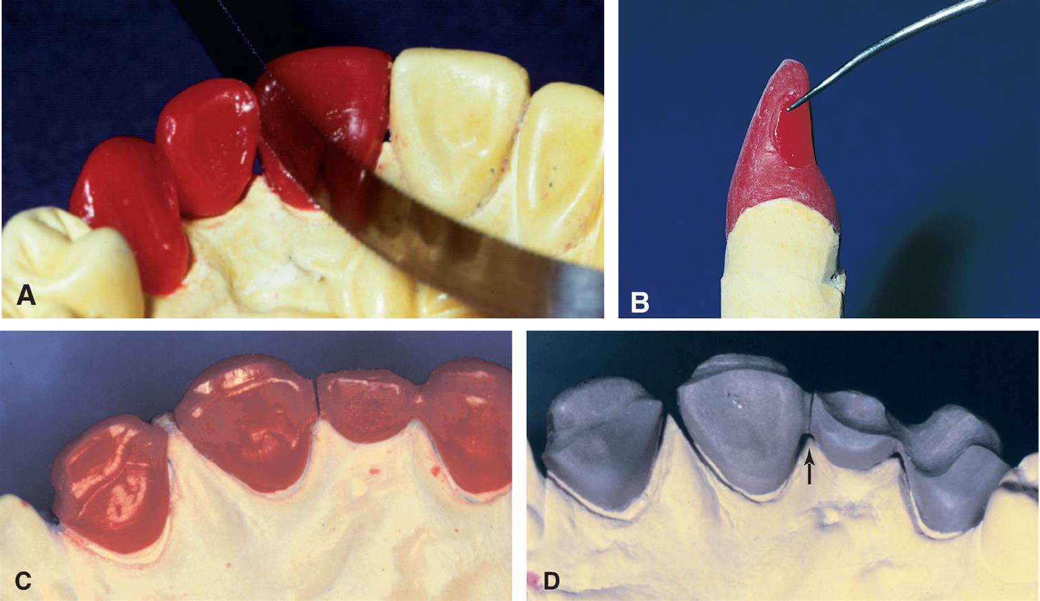
As with cast connectors, connectors to be soldered are waxed to final shape but are then sectioned with a thin ribbon saw (Fig. 27.7A and B); therefore, when the components are cast, the surfaces to be joined are flat, parallel, and a controlled distance apart. This allows accurate soldering with a minimum of distortion.9 Molten solder flows toward the location where the temperature is highest. In metal, the two flat surfaces previously created in wax retain heat, which ensures that the highest temperature is in the connector area.
Soldering gap width
As gap width increases, soldering accuracy decreases.10 Extremely small gap widths can prevent proper solder flow and cause the joint to be incomplete or weak.11 An even soldering gap of about 0.25 mm is recommended. If a connector area has an uneven soldering gap width, obtaining a connector of adequate cross-sectional dimension without resulting distortion is more difficult.
Nonrigid Connectors
The design of nonrigid connectors that are incorporated in the wax pattern stage consists of a mortise (also referred to as the “female” component) prepared within the contours of the retainer and a tenon (“male” component) attached to the pontic (Fig. 27.8). The mortise is usually placed on the distal surface of the anterior retainer. Accurate alignment of the dovetail or cylindrically shaped mortise is crucial; it must parallel the path of placement of the distal retainer (see Fig. 27.2). Paralleling is normally accomplished with a dental surveyor. When the cast is aligned, the path of placement of the retainer that will be contiguous with the tenon is identified. The mortise in the other retainer is then shaped so that its path of placement allows concurrent seating of the tenon and its corresponding retainer.
The mortise can be prepared freehand in the wax pattern or with a precision milling machine. Another approach is to use prefabricated plastic components for the mortise and tenon of a nonrigid connector (Fig. 27.9).
Materials ScienceM.H. Reisbick
Solder
Dental gold solders are given a fineness designation to indicate the proportion of pure gold contained in 1000 parts of alloy. For example, a 650-fine solder contains 65% gold. In an earlier designation,12 the solder was assigned a carat number, which indicated the gold content of the castings that were to be joined with the solder; an 18-carat solder could be used to solder castings fabricated of an alloy containing 75% gold. Because numerous alloys other than type IV gold are available today, many of which contain platinum-group metals, the carat designation is of little value.
Modern casting alloys have become so metallurgically complex that most manufacturers now recommend specifically formulated solders. One manufacturer (Kulzer GmbH) classifies traditional gold-containing solders as group I and others (termed special solders) as group II. Most of these have the brand name with a “pre” or “post” designation to indicate whether the solder is to be used for joining the components before or after porcelain application. The so-called preceramic solders are obviously high-fusing alloys, sometimes fusing only slightly beneath the softening point of the parent alloy to be joined. Ideally, they flow well above the fusion range of the subsequently applied porcelain. Postceramic solders must flow well below the pyroplastic range of the porcelain. For example, one popular silver-palladium (Ag-Pd) casting alloy has a specified melting range between 1232°C and 1304°C (2250 °F to 2380 °F). The recommended special presolder melts at 1110°C to 1127°C (2030 °F to 2061 °F), whereas the postsolder melts at 710°C to 743°C (1310 °F to 1369 °F). The porcelain fuses at about 982°C (1800°F), depending on time and temperature.
The composition of the solder determines its melting range, among other things. Some typical compositions and melting ranges are given in Table 27.1. The main requirement in soldering is to fuse safely below the sag or creep temperature of the casting to be soldered. Newer palladium casting alloys, by virtue of their higher melting ranges, have somewhat increased the reliability of the presoldering technique.13
Table 27.1
However, preceramic soldering is relatively difficult and can be structurally hazardous (Fig. 27.10). This may be because base metal solder constituents volatilize with overheating,14 which then results in microporosity, or pitting. The melting range of presolders is quite narrow because silver and copper (the usual modifiers of temperature range) cannot be used in the alloy; these elements discolor porcelain on contact. Another consideration is the oxide necessary for the chemical adherence of porcelain. Porcelain does not chemically bond equally well to all solders.
Other requirements of solders are their ability to resist tarnish and corrosion, to be free flowing, to match the color of the units that will be joined, and to be strong. These factors also depend on the chemical composition of the solder.
Resistance to tarnish and corrosion is determined by a solder's noble or precious metal content and its silver-to-copper (Ag/Cu) ratio.15 In addition, if the compositions of the solder and workpiece differ, galvanic corrosion may occur.
During the soldering procedure, the solder must flow freely over clean and smooth surfaces. These surfaces should be smoothed with abrasive disks, not with rubber wheels or polishing compounds. The phenomenon of free flow is termed wetting, during which remelting or realloying of the surface of the units to be joined must not occur.16 Solder flow is increased by the addition of silver and decreased by the presence of copper. Fig. 27.11 depicts a properly made solder joint. Note that the filler metal has joined the surfaces of the two castings without penetrating either one.

Lower-fineness gold solders are often more fluid and are generally chosen for joining castings. If necessary, proximal contacts with a solder of higher fineness can also be added because this tends to flow less freely. However, the exact minimally acceptable fineness necessary for resisting tarnish and corrosion has not been conclusively established; 615 or 580 fineness is probably the lower limit of clinical acceptability.
The last requirement, strength, is easily satisfied by most solders and is usually greater than that of the soldered parent metal, provided that the procedure is followed carefully.10 In addition, most solders harden during cooling because of the “order-disorder” transformation and the formation of other intermetallic phases, which occur at grain boundaries. Brittleness is frequently encountered with gold-based copper-containing solders. As with type III and type IV gold casting alloys, the gold-copper order-disorder (or discontinuous phase-hardening) mechanism causes similar changes in the solder's microstructure.17 Simply stated, with these solders, cooling to room temperature results in a brittle joint. The joints are strong but have no ductility. Some solder joints are weakened by notches.18 This means that soldered connectors should be well polished to prevent fracture.
FPDs fabricated with type III gold alloys and joined interproximally with traditional gold-based solders are usually water quenched 4 to 5 minutes after soldering is complete. Quenching immediately after soldering causes the FPD to warp; failure to quench results in a joint with little or no ductility. A brittle joint may easily fracture. Thus a disadvantage of postceramic soldering is the loss of joint ductility. Because the components are partially porcelain, quenching is not done, because porcelain fracture would occur.
Soldering Flux and Antiflux
Soldering Flux
Soldering flux is applied to a metal surface to remove oxides or prevent their formation. When the oxides are removed, the solder is free to wet the clean metal surface.
Borax glass (Na2B4O7) is frequently used with gold alloys because of its affinity for copper oxides. An often-cited soldering flux formula19 is borax glass (55 parts), boric acid (35 parts), and silica (10 parts). These ingredients are fused together and then ground into a powder.
Fluxes are available in powder, liquid, or paste form. The paste is popular because it can be easily placed and confined. To make pastes, the flux powder is mixed with petrolatum. The petrolatum excludes oxygen during heating and eventually carbonizes and then vaporizes.
New fluxes are available for use with non–gold-based alloys. Their formulas are not generally published. At present, none of the new fluxes are totally capable of preventing oxide formation during heating of the base metal or nonnoble alloys. An example of a rapidly forming oxide on a base metal occurring during a simulated postsoldering is shown in Fig. 27.12. Soldering of base metal alloys is still unpredictable.20
All fluxes should be prevented from contacting porcelain-veneered surfaces. The contact causes pitting and porcelain discoloration.
Soldering Antiflux
Antiflux is used to limit the spreading of solder. It is placed on a casting before the flux application to limit the flow of molten solder. When the metal surfaces are clean, any excess solder introduced into the work gap tends to flow into undesirable areas. The antiflux helps prevent this.
Graphite (from a pencil) is often used as an antiflux. However, the carbon easily evaporates at higher temperatures, leaving the workpiece unprotected. A more reliable antiflux is iron oxide (rouge) in a suitable solvent such as turpentine, which can be painted on the casting with a small brush.
Soldering Investment
Soldering investments are similar in composition to casting investments (see Chapter 22). Casting investments, both gypsum and phosphate bonded, mixed with water only, have been used for soldering. However, the refractory component in casting investments usually creates unwanted thermal expansion and therefore excessively separates the units to be joined. Soldering investments ideally contain fused quartz (the lowest thermally expanding form of silica) as their refractory component.
Invested units expand during heating, and they should do so at the same rate as the castings. The units must be correctly gapped so that they do not touch. When the work units are allowed to touch, distortion and porous, inadequate joints result.12 Alternatively, excessive gap spaces cause undersized mesiodistal FPD widths because of solder solidification shrinkage. However, Ryge12 showed that the gap space closes somewhat during heating, and so it is doubtful that the alloy and investment truly expand equally or at the same rates. Several commercial soldering investments are available; these should be used whenever possible.
Joining Base Metals
Titanium and Titanium Alloys
The advent of titanium and its alloys, as with cobalt-chromium-nickel, has brought a new challenge to joining cast units. Titanium also responds to high heat with an increased oxide formation, which results in a poor union between components to be joined. A reasonable solution has proved to be welding, by either laser or plasma.21 Advantages include less heat distortion and a compositionally uniform joint. Joining with the same chemical element or elements thus minimizes detrimental galvanic degradation. Much work yet remains to render titanium a suitable replacement for noble casting alloys.
Selection of Soldering Technique
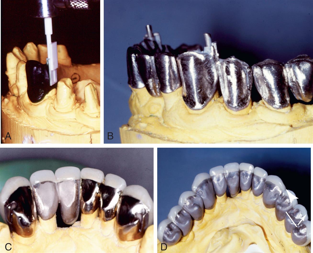
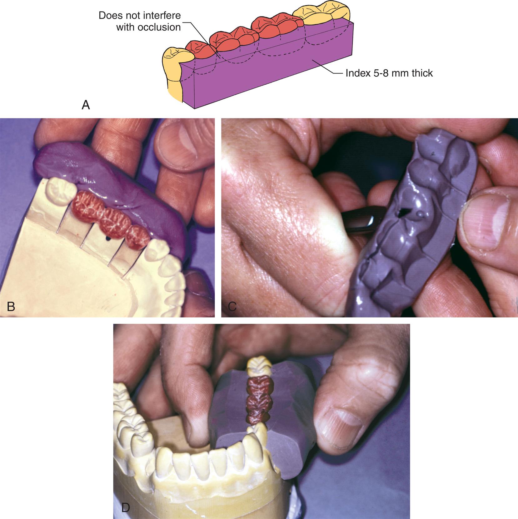
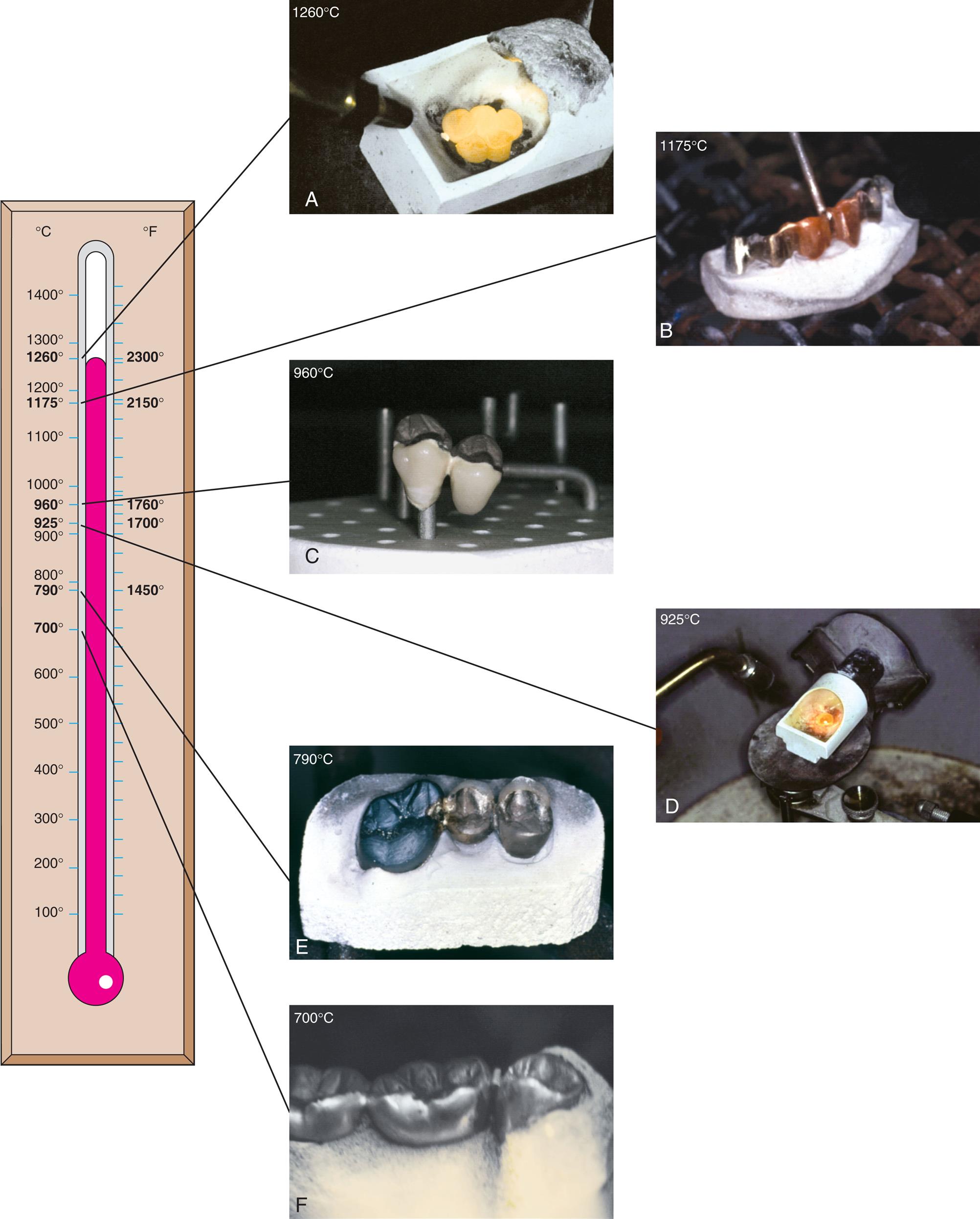
When FPDs are assembled by soldering, the relative position of the components is recorded with a soldering index (Fig. 27.13) on the definitive cast or intraorally (Fig. 27.14). If pontics are made individually, they can be difficult to position properly in relation to the abutment teeth. Although a positioning index made previously upon completion of the wax pattern can be helpful (Fig. 27.15), the pontics should be connected to one of the retainers with a cast connector because this stabilizes them and makes accurate positioning in relation to the other retainer much easier. To understand the selection of soldering technique, a thorough knowledge of the fusing ranges of all materials involved in the FPD is essential (Fig. 27.16).
Soldering of all-metal FPDs consisting of type III or IV gold units requires the use of a low-fusing solder. The procedure is referred to as conventional soldering. Through the use of the same low-fusing solder, regular gold retainers can also be connected with metal-ceramic components. A gas-air torch is used for either of these procedures.
For FPDs consisting of metal-ceramic units, the soldered connectors may be made either before the ceramic application with high-fusing solder (≈1100°C [2012°F]) or after the ceramic application with lower-fusing solder (750°C [1382 °F]). Soldering before ceramic application is called pre–ceramic application soldering or presoldering. Soldering of metal-ceramic crowns after their completion is referred to as postsoldering. Many alloys can be combined by means of either presoldering or postsoldering. However, presoldering has been found to be less reliable,10 with a number of apparently sound connectors exhibiting negligible tensile strength. Considerable variation in solder joint strength has also been recorded after laboratory testing,22 which emphasizes the special care needed to avoid defective connectors.
Base metal alloys can be difficult to solder because they oxidize; oxidation must be controlled with special fluxes, although excessive fluxing can lead to undesirable inclusions and weak connectors. In one study,23 investigators found that 20% of postsoldered joints involving base metal alloys had to be resoldered because they were so weak that they broke with finger pressure. In another study, Anusavice et al.24 demonstrated great variability in solder joint quality with these alloys, with no consistent relationship of strength to gap width. These authors found that most failures occurred through the solder and were attributable to voids caused by gas entrapment or localized shrinkage. With experience and careful adherence to the manufacturer's recommended techniques and materials, soldered connectors made of base metal alloy can be reliable.25 However, because of the problems of soldering base metal alloys, various alternative procedures have been advocated. These include making the soldered joint through the center of the pontic to increase the area soldered26 and connecting the parts by a second casting procedure, with the molten metal flowing into undercuts in the sectioned pontic.27
Soldering Metal Fixed Partial Dentures
Type III and type IV gold retainers of FPDs are soldered with gold solder with fineness ranging from 615 to 650. An occlusal plaster index or autopolymerizing resin index is fabricated intraorally or in the dental laboratory; after investment, a gas-air torch can be used to solder the components. A disadvantage of the soldering procedure is that it requires an additional step, in comparison with a one-piece casting. However, soldering simplifies the manipulation of wax patterns. For instance, when a three-abutment FPD with two splinted abutments (e.g., two premolars) is fabricated, access to the interproximal margins of the two splinted abutments is often very difficult during the reflowing and finishing steps. Soldering such retainers enables the dentist to shape and adjust the retainers individually, with improved access for finishing procedures. Conventional soldering requires a gas-air torch; soldering can also be performed in a furnace.
Soldering Metal-Ceramic Fixed Partial Dentures
Presoldering
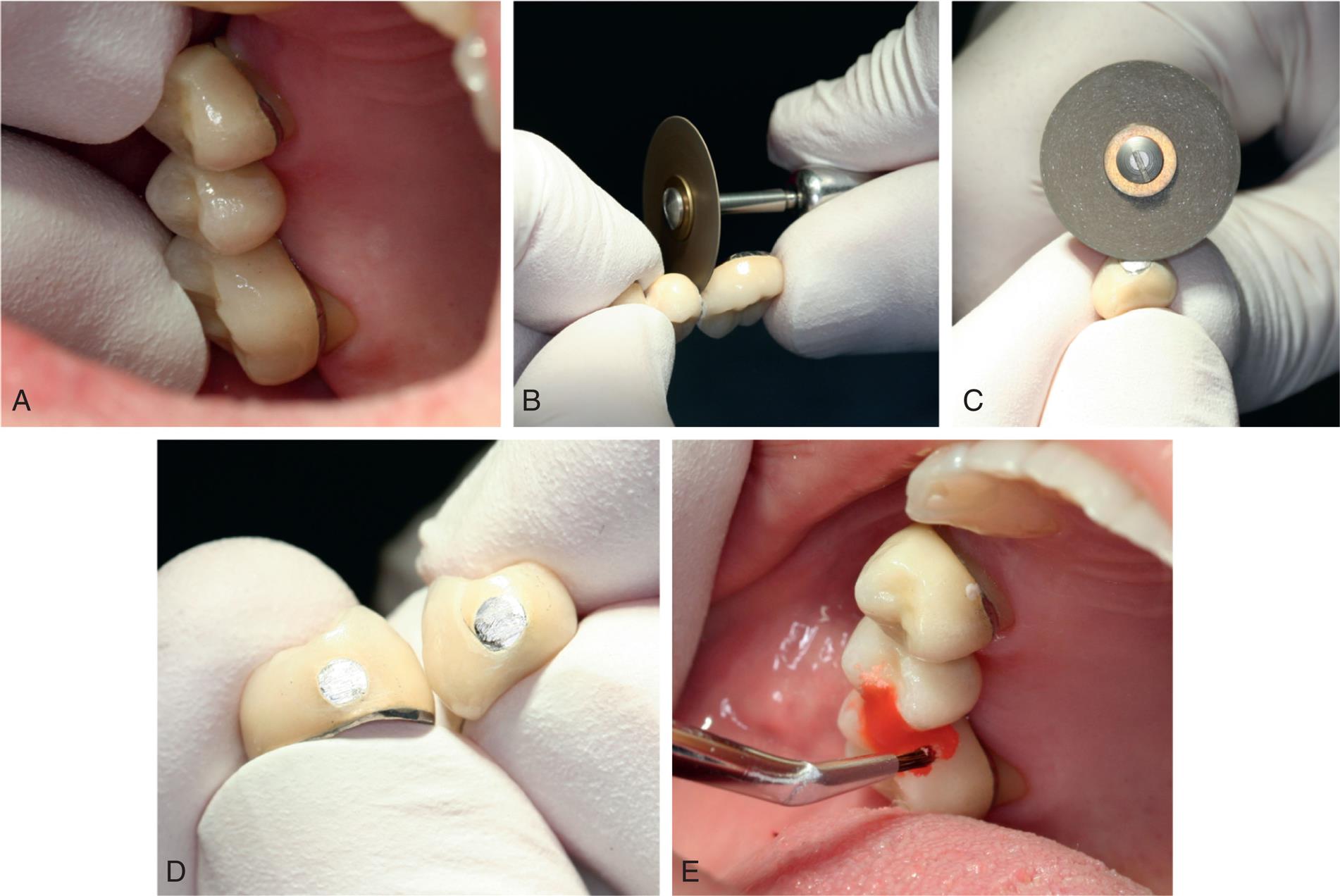
Once a metal-ceramic framework has been assembled by presoldering, the subsequent procedures are the same as if it had been cast in one piece. This has the advantage of allowing the connected prosthesis to be evaluated in the mouth in the unglazed state. Any necessary adjustments can be made to the porcelain, which fuses at a lower temperature than does the presoldered connector. However, with presoldering, contouring the proximal embrasures so that the units resemble natural teeth may be more difficult. A very thin diamond disk is helpful in such contouring.
A disadvantage results from having to apply the porcelain to a longer structure, which needs support during firing to prevent high-temperature deformation or sag. Sag can be a particular problem with the high–gold content ceramic alloys because they have a lower melting range. High–palladium content or base metal alloys exhibit little sag during firing. Presoldering requires a gas-oxygen torch.
Postsoldering
Postsoldering is necessary when regular gold and metal-ceramic units are being combined in an FPD. The regular gold melts if it is subjected to the high temperatures needed for porcelain application; therefore, all porcelain adjustment and firing, including that for the final characterization and glazing, must be completed before the soldering. If further corrective adjustment is needed after soldering, the porcelain must be polished, or the joint must be separated, after which additional porcelain can be added as needed, the restorations can be reglazed, a new index can be made, and the FPD can be resoldered.
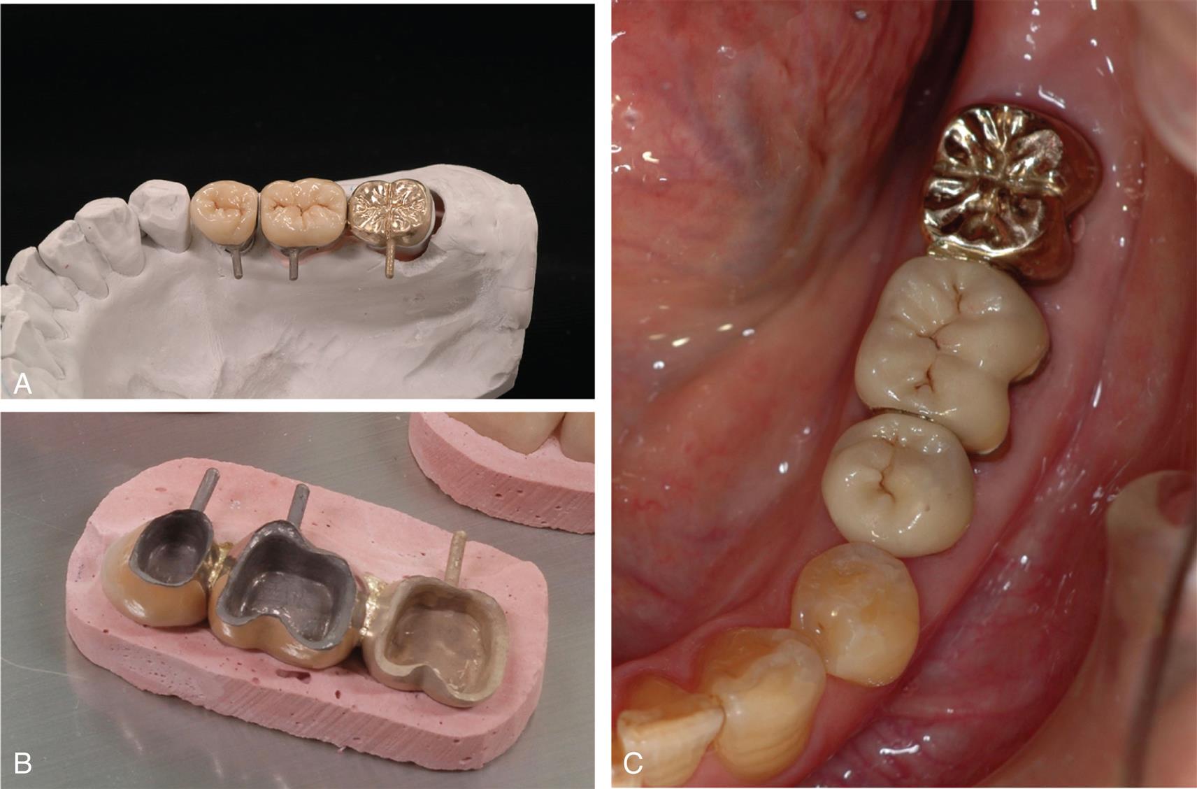
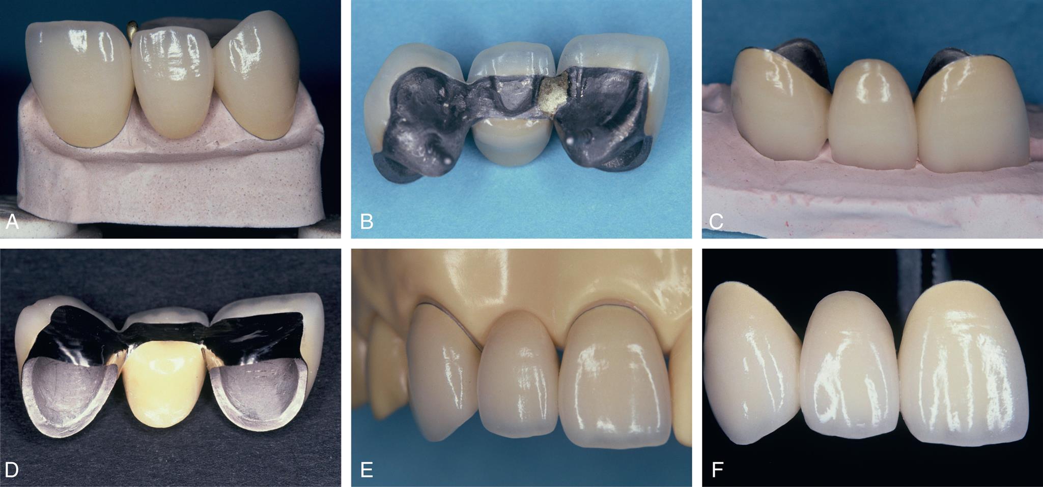
Because the proximal areas are shaped before soldering, a postsoldered connector can often be made to look more natural than a presoldered or cast connector (Fig. 27.17). In addition, customized firing supports are not needed because sag is not a problem (the lengths of the individual components are shorter). Postsoldering is performed either in a porcelain furnace or with a gas-air torch.
Heat Sources
Torch Soldering
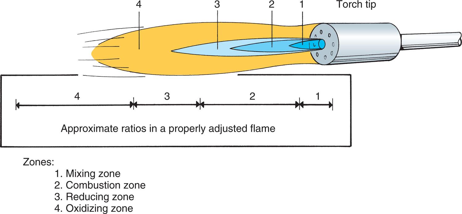
When a gas-air torch is used as the heat source to melt the solder, metal-ceramic restorations are preheated in an oven to minimize the risk of cracking of the porcelain veneer. To prevent oxidization of the joint surfaces, the reducing (non-oxidizing) portion of the flame is used (Fig. 27.18), and an appropriate flux is applied (some soldering fluxes are unsuitable because they discolor the porcelain). To prevent uneven heat distribution, which could result in fracture, the flame is never concentrated in one area but is kept in constant motion.
Some dental technicians believe that the flow of solder is more controllable during torch soldering than during oven soldering because a slight temperature differential can be created and the solder always flows toward the hotter point. This makes torch soldering useful when the connector has not been well designed in wax, and a minor temperature difference can deliberately be created in the assembly to help direct the flow of the molten solder to ensure adequacy of the connector.
Oven Soldering
Furnace or oven soldering is performed under vacuum pressure or in air. A piece of solder is placed at the joint space, and the casting and solder are heated simultaneously.
Criticism of this technique has been based on earlier observations28 that less porosity resulted when castings were brought to soldering temperature before the solder was applied. The method does not allow the moment of solder fusion to be observed. (Some porcelain furnaces have an observation window for postsoldering.) This may be important because the longer the solder remains molten, the more it dissolves the parent metal and consequently weakens the joint.11 Nevertheless, joints with strength similar or superior to that of the parent metal have been demonstrated10 when oven soldering was used.
A different technique may be appropriate if the porcelain furnace has a horizontal muffle with a fixed floor. The soldering assembly is heated above the fusion point of the solder, the muffle door is opened, and the solder is fed into the joint space (Fig. 27.19).
Microwave Soldering
Microwave heating has been used for dental soldering on an experimental basis.29,30 The process has the advantage of using less energy than conventional oven soldering, and joint strength has been found to be comparable with that produced by traditional methods.29,30
Laser Welding
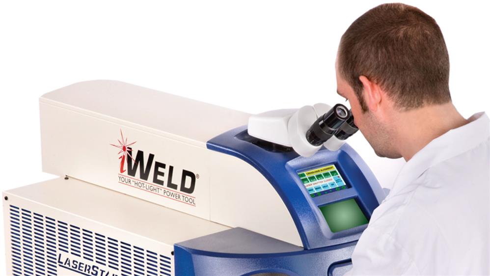
Laser energy is extensively used for welding (Fig. 27.20) in many industries and has been described in dentistry since the 1970s.31,32 Laser assembly of FPDs has been reported to have higher strength33 and reduced corrosion34 in comparison with conventional soldering, although laser-welded connectors seem as susceptible to fatigue failure35 and may be less suitable for joining noble-metal alloys than for base-metal alloys.29 Laser welding is a practical way to join cast or milled titanium or cobalt-chromium components (i.e., if these are to be used for implant-supported prosthesis frameworks36–39).
Soldering Accuracy
Controversy exists as to the relative accuracy of FPDs that are cast in one piece, presoldered, or postsoldered. Individual dental laboratory technicians often obtain consistently better results with one particular technique, but scientific evidence is conflicting.40–43 In evaluating clinical work to determine whether cast or soldered connectors provide better results, the determining factor should be the fit of the individual retainers. This should be optimized through the investing and casting process (see Chapter 22) to minimize the risks of incomplete seating or excessive luting agent space. In some situations, it may be impossible to cast a long-span FPD with ideal retainer dimensions and ideal interabutment dimensions; the challenge lies in obtaining enough interabutment expansion without making the retainers too loose. In such circumstances, a soldered connector may provide better accuracy. The situation is reversed for fabricating frameworks for implant-supported prostheses (see Chapter 13): The fit of the individual units is determined by the implant manufacturer. Only the overall abutment-to-abutment fit is under the control of the technician. However, an accurate, passively fitting implant-supported framework is crucial for avoiding damaging forces. It is not yet clear whether accurate implant-supported frameworks are most effectively made with one-piece castings or as sectioned and soldered or laser-welded units.42–44
Soldering Technique
Armamentarium
Step-by-Step Procedure
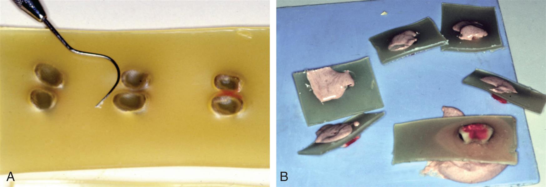
Occlusal Soldering Index
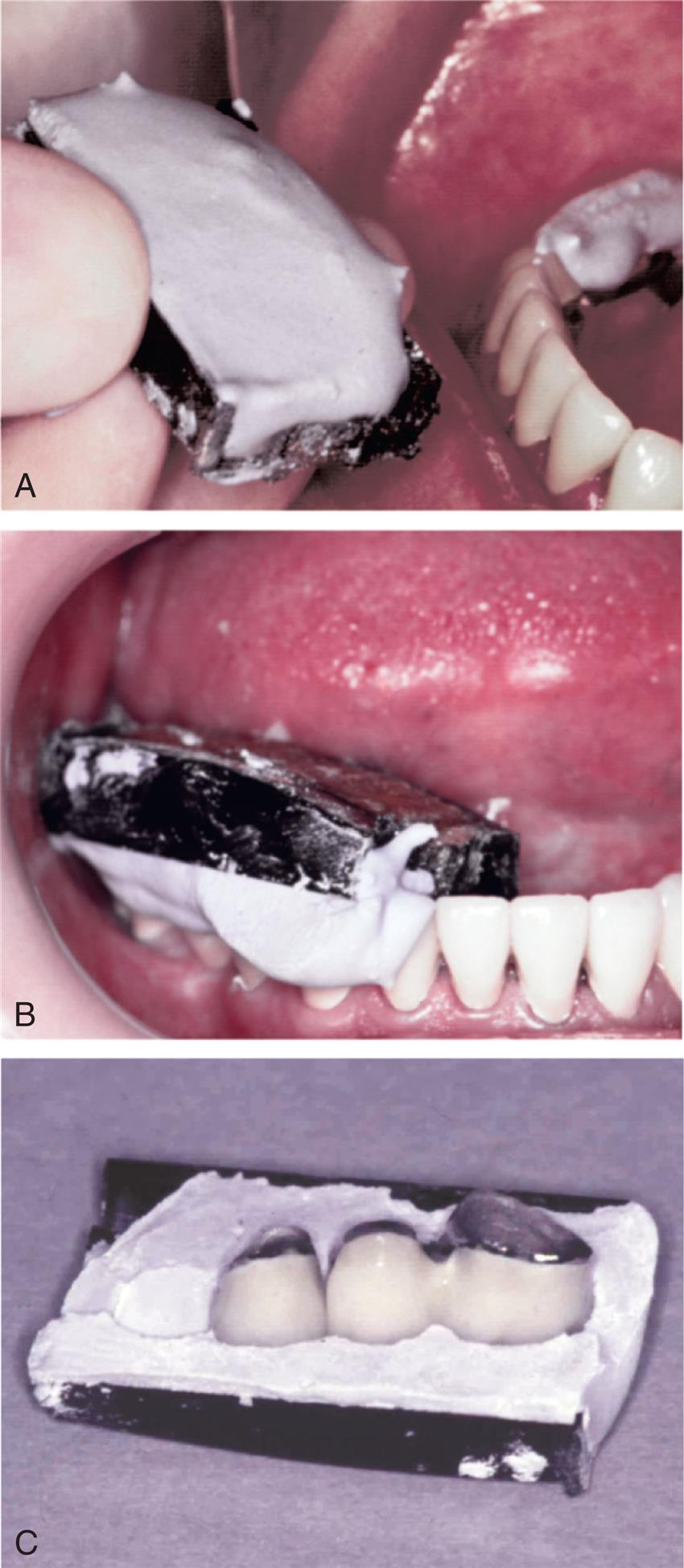
Intraoral plaster or ZOE is used to make an impression of the occlusal surfaces of the FPD to capture the relative relationship of the individual FPD components and transfer this to the laboratory. This procedure can also be performed in the laboratory if the technician is satisfied that the individual components are seated completely on an accurate definitive cast. An advantage of an occlusal index (Fig. 27.21; see also Fig. 27.3) is that after the soldering procedure has been completed, the FPD can be reseated in the index, and soldering accuracy can be verified (sometimes a small amount of plaster must be removed in the area where the solder has been added, to ensure seating).
- 1. Grind the connector surfaces of the finished castings with a stone or disk to remove surface oxides. Then fully seat the castings on the definitive cast or in the patient's mouth. Postsoldering connectors are best indexed intraorally after the contour and appearance have been perfected. If necessary, the soldering gap can be adjusted at this time (gap distance, 0.25 mm). The castings can be seated intraorally with a small quantity of low-viscosity impression material to ensure that they are not disturbed during the indexing.45
- 2. Make an impression plaster registration in a small tray or on a sheet of baseplate wax for the occlusal index. As an alternative, an index can be made with ZOE paste, a technique that has yielded46 consistent and accurate recordings. The index should not cover the margins of regular gold retainers because these are to be embedded in the investment to prevent their accidental melting during soldering.
- 3. Trim the index to fully expose the margins before investing (Fig. 27.22).
Investing
- 4. Seat each casting into the index, and lute it into place with sticky wax.
- 5. Have wax flow into the connector area to prevent the investment from entering.
- 6. To create a space that will help the solder spread, adapt sprue wax gingival to the solder joint. Burying the units completely in the investment makes soldering difficult because the unnecessary bulk of the investment prevents rapid heating of the castings.
- 7. Protect any glazed porcelain from contacting the investment by coating it with wax before investing. To protect regular gold margins from the soldering flame, they should be embedded in the investment; otherwise, they may become overheated and melt. For the same reason, all margins should be embedded in the investment before presoldering.
- 8. Box the assembly with suitable sheet wax.
- 9. Mix the investment carefully, and have it flow into the castings without trapping any air. Use only slight vibration so that the castings are not displaced from the index.
- 10. Allow the invested block to bench set before removing the wax and preheating.
Autopolymerizing Resin Soldering Index
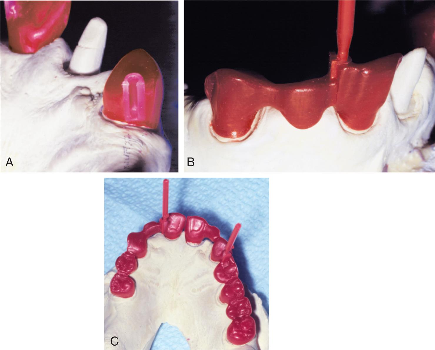
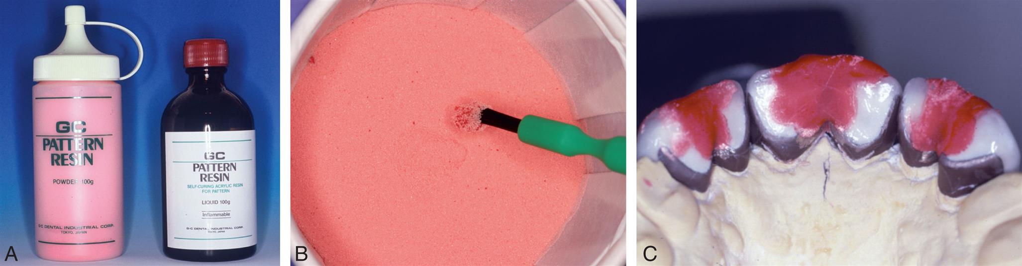
A plaster or ZOE occlusal index is less suitable for the registration of anterior restorations. Because of the thinness of their incisal edges, these units are less stable, and accurate repositioning is more difficult. For this reason, autopolymerizing resin (Fig. 27.23) is recommended, although the resin burns off during the procedure. Therefore, the accuracy of the soldering procedure can be verified only intraorally.
- 1. Join the completed units together with autopolymerizing resin. The resin will later burn out, leaving no residue that could interfere with the casting.
- 2. Apply the resin with a bead technique. This minimizes the distortion from polymerization shrinkage. Excessive bulk of resin reduces the accuracy of the technique,47 but sufficient material must be present to ensure that the components do not break (because they cannot then be accurately reseated in the index). The resin should extend onto the incisal edges of the retainers.
- 3. When the resin has fully hardened, carefully loosen the prosthesis from the abutments. Then replace it and check whether distortion has occurred. This is done in the same way as the evaluation of a finished FPD. It must be stable with no marginal discrepancies (see Fig. 27.23C). The prosthesis should be invested without delay; otherwise, the resin index will become distorted.48
Investing
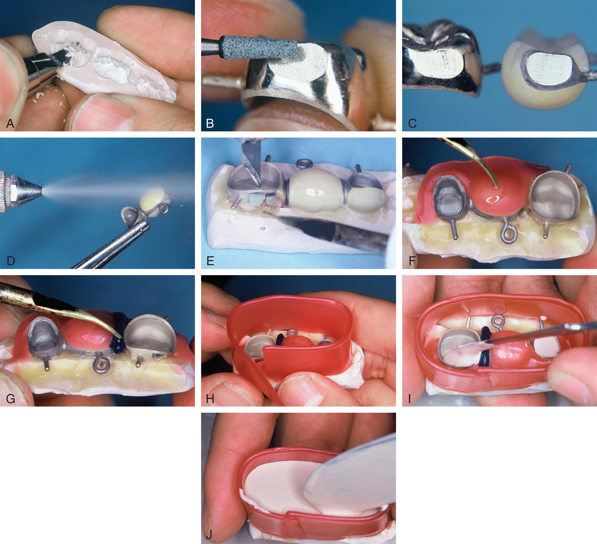
This process is illustrated in Fig. 27.24.
- 4. Warm a sheet of wax and push the cervical margins of the restorations through it. Then seal it along the axial wall with a warmed instrument. This protects the porcelain from contact with the soldering investment.
- 5. Fill the castings with soldering investment, and blot excess water from the remaining investment, forming it into a patty on a slab or tile.
- 6. Seat the restorations on the patty. When a joint is to be oven-soldered, the restoration should be angled forward so that the solder can be placed above the joint before the block is set inside the furnace.
Wax Removal and Preheating
This process is illustrated in Fig. 27.25.
- 1. If a plaster or ZOE index was used, remove it after the investment has fully set. This separation is most effectively accomplished after the wax is removed with boiling water. The joint space must be free of investment. Flowing of a little flux into the joint space while the soldering block is still warm from wax removal is recommended. This prevents small particles from inadvertently falling into the gap. Be aware that many special soldering investments have low strength, and the assembly is easily broken at this stage.
- 2. Preheat the investment in a burnout furnace to 650°C (1202 °F) for low-heat soldering or 850°C (1562 °F) for presoldering. Acrylic resin indexes are removed by heating slowly to 300°C (572 °F), at which time most of the resin will have burned away.
- 3. Heat the block to 650°C (1202 °F) until all traces of wax and resin have vaporized, and then transfer it to the soldering stand or porcelain furnace.
Torch Soldering (Low Heat)
This process is illustrated in Fig. 27.26.
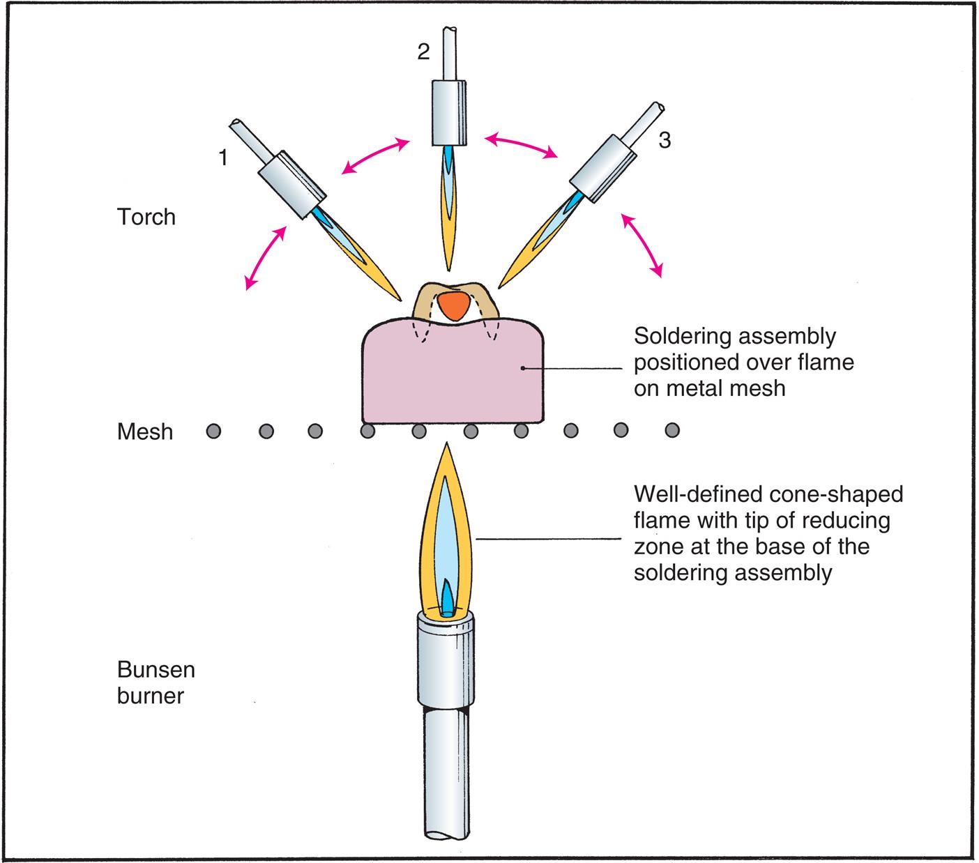
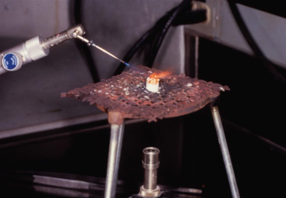
- 1. Transfer the assembly to a soldering stand over a Bunsen burner, and place a piece of solder above the gap. Adjust the gas-air torch to produce a sharp blue cone (as for casting), and then reduce the air for a softer or less pointed “brush” flame. The reducing zone of the flame is used to heat the investment block. The flame is directed at the lingual surface of the block rather than at the casting.
- 2. Heat evenly and slowly, moving the tip of the flame constantly. This is particularly important in postsoldering because the porcelain may easily crack. When the metal glows brightly, the solder melts and flows into the joint space.
- 3. Quickly move the flame to the facial. When the solder “spins” in the joint, remove the flame.
- 4. Extinguish the flame, and let the soldered prosthesis cool for 4 or 5 minutes before quenching (unless there is porcelain on the restoration, in which case it should cool to room temperature). Earlier quenching may lead to distortion, whereas prolonged bench cooling increases the brittleness of the joint.
Torch Soldering (High Heat)
This process is illustrated in Fig. 27.27.
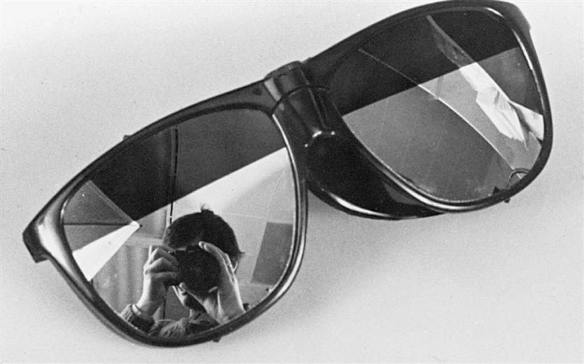
- 1. Wear dark glasses for eye protection (Fig. 27.28). Gas-oxygen torches for high-heat presoldering have a miniature needle tip so that the flame can be pinpointed on the joint space.
- 2. Place the solder above the gap and concentrate the reducing zone of the flame on the joint space.
- 3. When the solder melts, draw it into the joint and quickly “chase” it around with the flame (Fig. 27.29). The presolder may have a melting point close to that of the parent metal, and there is danger of melting a thin framework unless the flame is concentrated on the joint space (see Fig. 27.10).
Oven Soldering
This process is illustrated in Fig. 27.30.
- 1. Prepare a piece of solder by dipping it in liquid flux and melting it in a Bunsen flame to form a ball. The size of the ball is determined by the connector size and the joint gap.
- 2. Leave a short tail attached to the ball to help position it above the joint space. As an alternative, the solder can be fed into the joint area.
- 3. Put the assembly in the furnace and increase the temperature to melt the solder. A vacuum is not needed for oven soldering of noble-metal alloys. Air firing is preferred by some technicians because in a vacuum, there is always the chance of drawing entrapped gases to the surface of glazed porcelain, causing localized swelling or bloating.
Evaluation
If the solder fails to flow during torch soldering but forms a ball above the joint area, heating should be discontinued. The solder has oxidized, and further heating will melt the castings. If the solder has flowed properly, the completed joint can be evaluated for size before removal of the investment and, if necessary, reheated while still hot, with additional solder added. Excessive solder must be ground away during the finishing procedure.
If the connector has been designed properly and the solder has been properly positioned, no solder should run onto the occlusal surface or cover the margins. To prevent stray flow, a small amount of antiflux (rouge dissolved in turpentine) can be painted on critical areas before the assembly is heated. After bench cooling for about 5 minutes, the assembly is quenched (postsoldered metal-ceramic prostheses are always allowed to cool to room temperature), and the investment is broken away (Fig. 27.31). The connector is then carefully inspected. If signs of an incomplete joint are evident (i.e., visible porosity in the solder), they are removed by grinding with a fine disk; the units are then reinvested and resoldered.
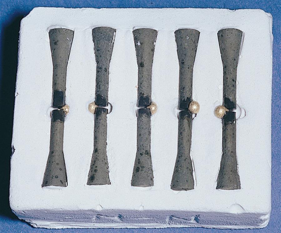
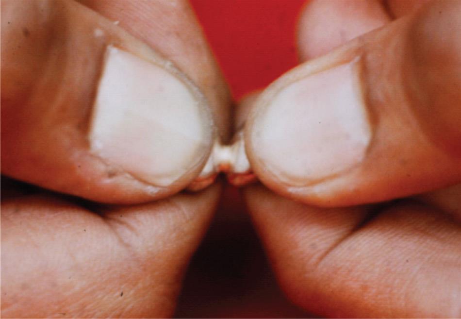
The joints must be tested for strength (Fig. 27.32). Any connector that can be broken by force of hand will not serve adequately in the mouth. Because broken connectors cannot be easily repaired intraorally once the prosthesis has been cemented, the entire restoration usually must be remade.
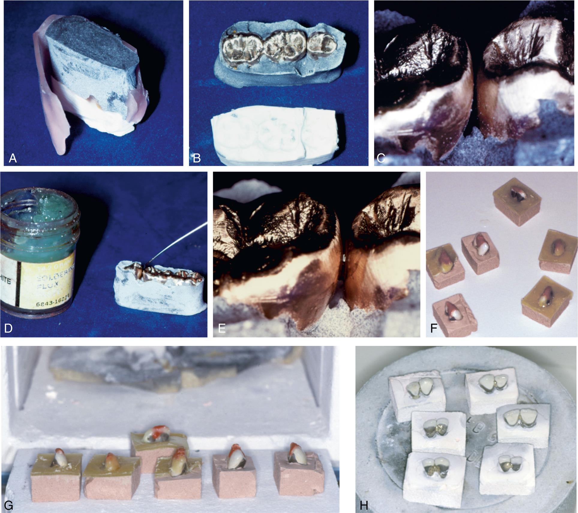
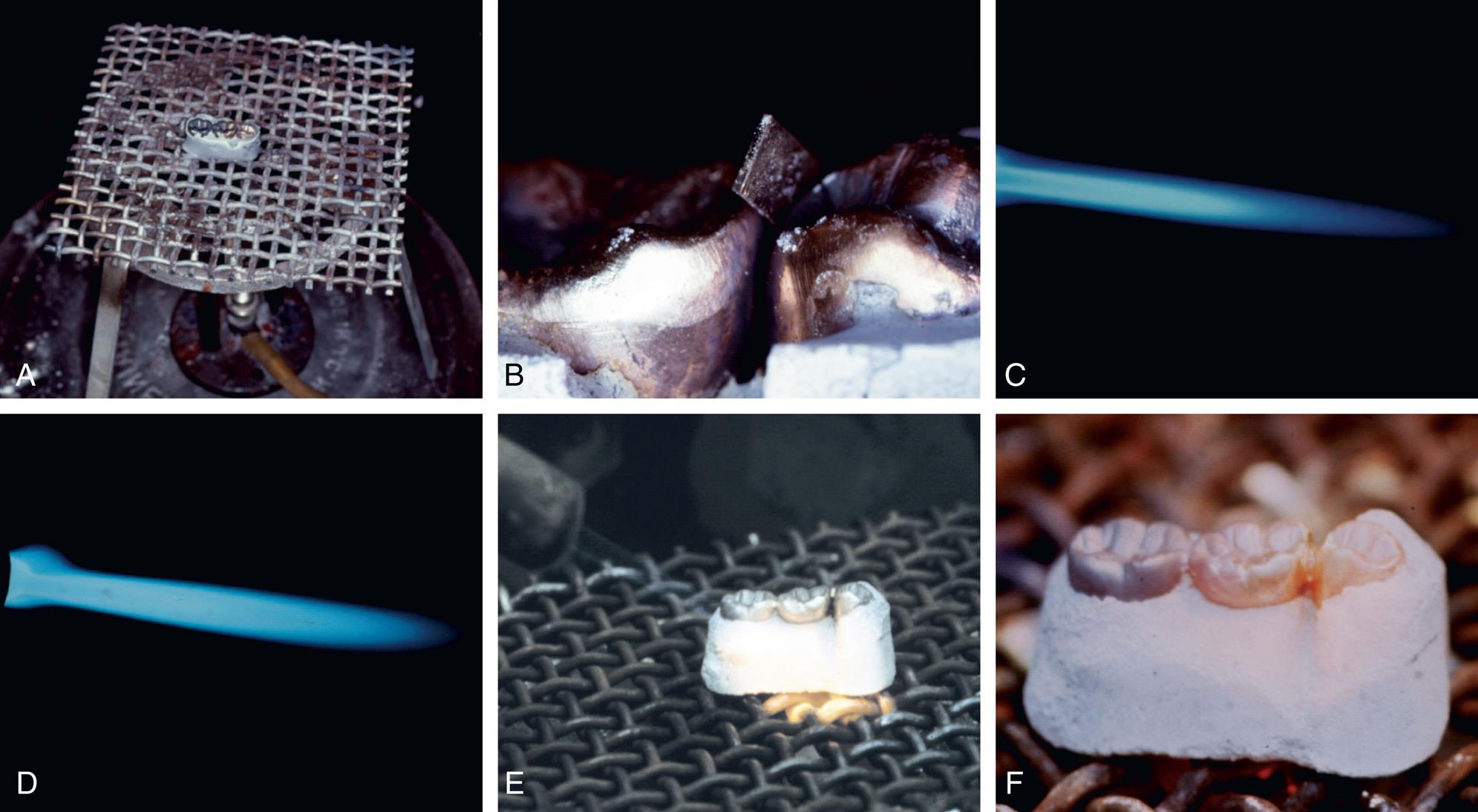
Review of Technique
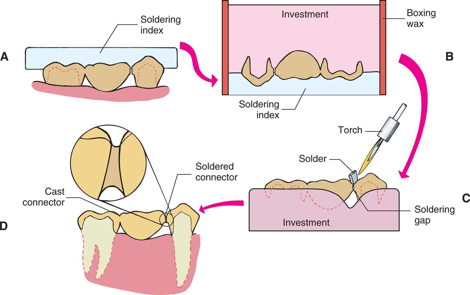
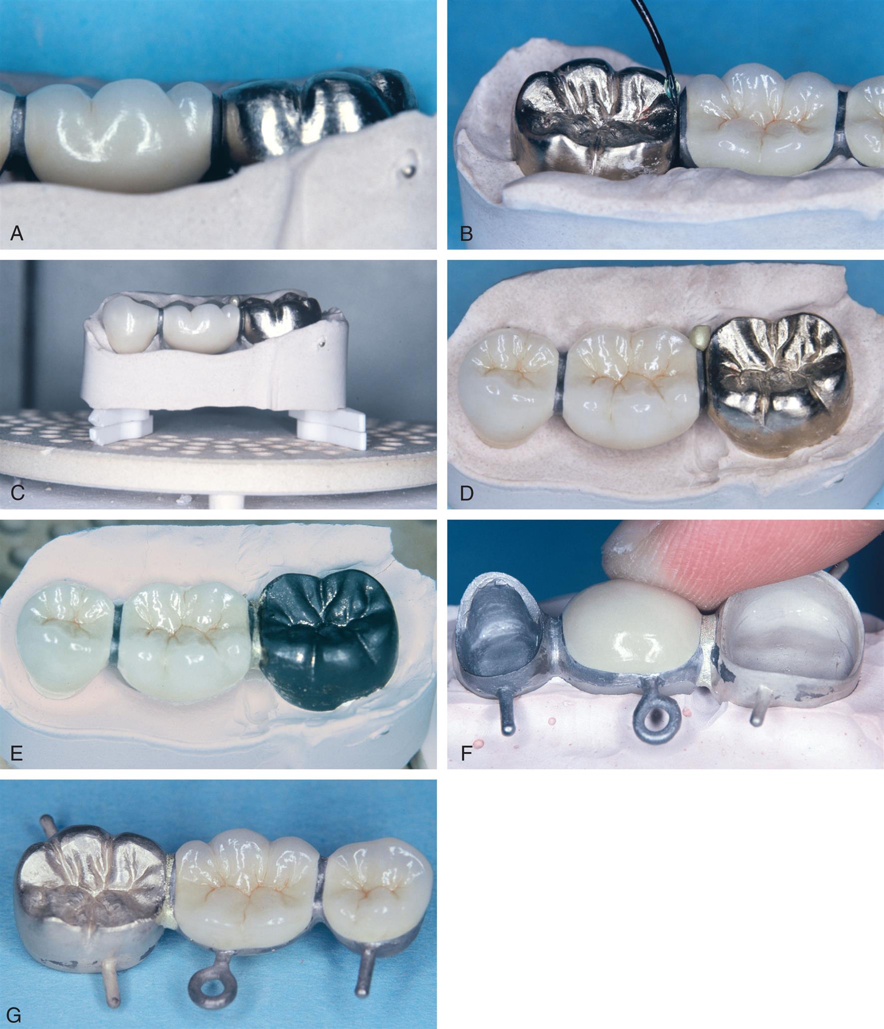
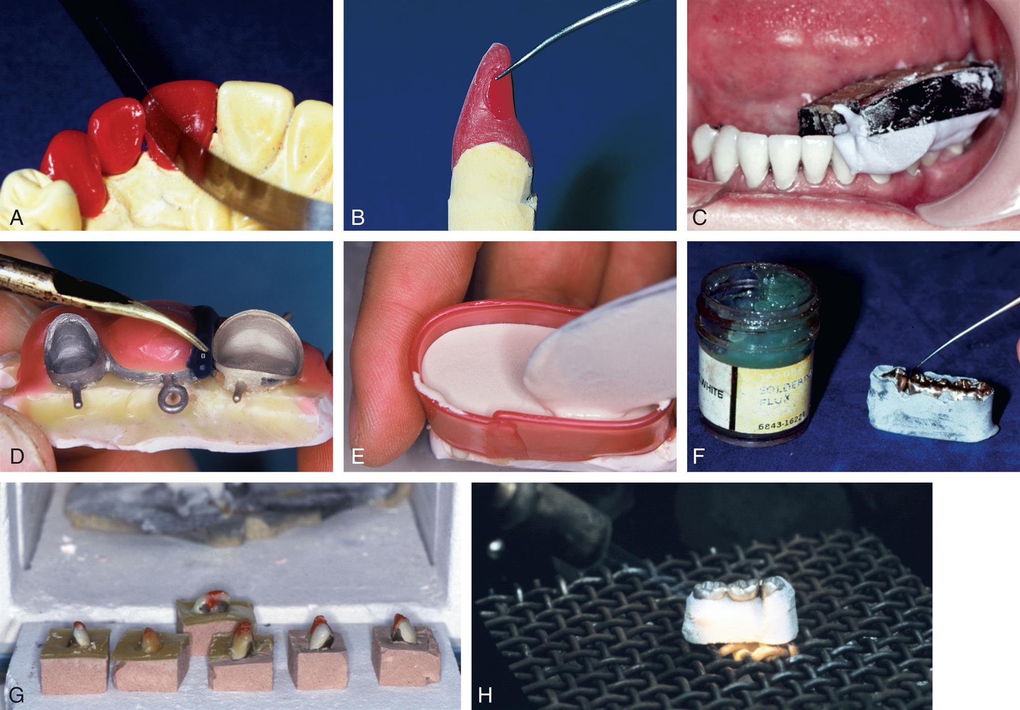
Fig. 27.33 summarizes the steps involved in FPD connector fabrication and should be referred to when the material is reviewed.
- 1. The design of connectors is determined in the wax pattern (see Fig. 27.33A).
- 2. All soldered connections require clean parallel surfaces. Gap width should be 0.25 mm (see Fig. 27.33B).
- 3. The units are indexed either from the definitive cast or in the patient's mouth (see Fig. 27.33C).
- 4. Wax is added to the indexed restorations to shape the soldering assembly. For metal-ceramic restorations, it is added to protect the porcelain (see Fig. 27.33D).
- 5. The units are invested, and the investment is allowed to bench set (see Fig. 27.33E).
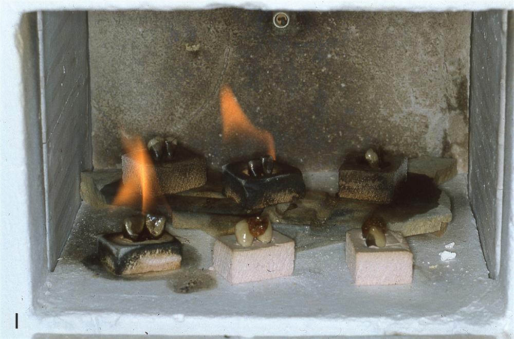
- 6. If a plaster or ZOE index is used, wax is eliminated with boiling water or an organic solvent, the joint is fluxed, and the assembly is preheated in a burnout furnace (see Fig. 27.33F).
- 7. If a resin index has been used, it is placed directly in the burnout furnace (see Fig. 27.33G).
- 8. The connectors are soldered with a torch or in a porcelain furnace (see Fig. 27.33H).
Summary
Connectors join individual retainers and pontics. Rigid or nonrigid connectors can be used. Connector size, shape, and position influence the success of an FPD. The use of soldered connectors can simplify the fabrication of larger FPDs, which may be cast separately in groups of one or two units and assembled after their individual fit has been verified. The technical procedures involved in soldering are not difficult. If the joint surfaces have been correctly designed and soldering gap width has been carefully controlled, the procedures are routine. All debris must be removed from the connector area because it interferes with surface wetting.
Conventional soldering involves the assembly of type II, III, or IV gold castings. Presoldering is the assembly of metal-ceramic substructures before porcelain application. Postsoldering is the assembly of metal-ceramic units after porcelain application. Heat sources used for soldering procedures include gas-air torches, gas-oxygen torches, furnaces, and laser units.
If the basic principles are understood and the technique has been mastered, these procedures are entirely reliable.
Study Questions
- 1. Contrast soldering, brazing, and welding.
- 2. Discuss how biologic, mechanical, and esthetic considerations affect connector size and position for each of the following classes of teeth: incisors, premolars, and molars.
- 3. When and why would a nonrigid connector be used? A loop connector?
- 4. Discuss fineness and carat. What is their importance in dental soldering?
- 5. How do soldering investments differ from conventional casting investments? Why?
- 6. What is flux? Antiflux? How do they work? Give several examples of each.
- 7. What are the fundamental differences among conventional soldering, postsoldering, and presoldering? When contrasting the last two techniques, identify the advantages and limitations associated with their use.
- 8. Describe the step-by-step procedures for two techniques to make a soldering index for a fixed partial denture. What are the respective advantages and limitations?