8: Pacemaker rhythms
Learning objectives
After reading this chapter, you should be able to:
- 1. Identify the components of a pacemaker system.
- 2. Discuss the terms triggering, inhibition, pacing, capture, electrical capture, mechanical capture, and sensitivity.
- 3. Describe the appearance of a typical pacemaker spike on the electrocardiogram (ECG).
- 4. Describe the appearance of the waveform on the ECG produced as a result of atrial pacing and ventricular pacing.
- 5. Explain the differences between single-chamber and dual-chamber pacemakers.
- 6. List three types of pacemaker malfunction.
- 7. Describe how to analyze pacemaker function on the ECG.
Key terms
atrioventricular (AV) interval: In dual-chamber pacing, the length of time between an atrial sensed or atrial paced event and the delivery of a ventricular pacing stimulus; analogous to the PR interval of intrinsic waveforms; also called the artificial or electronic PR interval.
capture: The successful conduction of an artificial pacemaker’s impulse through the myocardium, resulting in depolarization.
escape interval: Time measured between a sensed cardiac event and the next pacemaker output.
failure to capture: A pacemaker malfunction that occurs when the artificial pacemaker stimulus is unable to depolarize the myocardium.
failure to pace: A pacemaker malfunction that occurs when the pacemaker fails to deliver an electrical stimulus at its programmed time; also referred to as failure to fire or failure of pulse generation.
oversensing: A pacemaker malfunction that results from inappropriate sensing of extraneous electrical signals.
paced interval: Period between two consecutive paced events in the same cardiac chamber; also known as the automatic interval.
sensitivity: The extent to which an artificial pacemaker recognizes intrinsic cardiac electrical activity.
threshold: The minimum amount of voltage (i.e., milliamperes) needed to obtain consistent capture.
undersensing: A pacemaker malfunction that occurs when the artificial pacemaker fails to recognize spontaneous myocardial depolarization.
Pacemaker systems
A cardiac pacemaker is a battery-powered device that delivers an electrical current to the heart to stimulate depolarization. A pacemaker system consists of a pulse generator and pacing leads. A pacing lead is an insulated wire used to carry an electrical impulse from the pulse generator to the patient’s heart. It also carries information about the heart’s electrical activity back to the pacemaker. The pulse generator is the power source that houses a battery and electronic circuitry. The circuitry works like a computer, converting energy from the battery into electrical pulses. The pacemaker responds to the information received either by sending a pacing impulse to the heart (i.e., triggering) or by not sending a pacing impulse to the heart (i.e., inhibition).
An artificial pacemaker can be external (a temporary intervention) or implanted.
Temporary pacing routes
The pulse generator of a temporary pacemaker is located externally. An external pacemaker may be used to control transient disturbances in heart rate or conduction resulting from drug toxicity or that occur during a myocardial infarction (MI) or after cardiac surgery when increased vagal tone is often present. Temporary pacing can be accomplished through transvenous, epicardial, or transcutaneous means.
Transvenous pacing
Transvenous pacemakers stimulate the endocardium of the right atrium or ventricle (or both) using an electrode introduced into a central vein, such as the subclavian, femoral, brachial, internal jugular, or external jugular vein. Complications of temporary transvenous pacing include bleeding; infection; pneumothorax; cardiac dysrhythmias; MI; lead displacement; fracture of the pacing lead; hematoma at the insertion site; perforation of the right ventricle with or without pericardial tamponade; and perforation of the inferior vena cava, pulmonary artery, or coronary arteries because of improper placement of the pacing lead.
Epicardial pacing
Epicardial pacing is the placement of pacing leads directly onto or through the epicardium. Epicardial leads may be used when a patient is undergoing cardiac surgery and the heart’s outer surface is easy to reach.
Transcutaneous pacing
Transcutaneous pacing (TCP), also called temporary external pacing or noninvasive pacing, uses electrical stimulation through two pacing pads positioned on a patient’s torso to stimulate contraction of the heart. The electrical stimulus exits from the negative terminal on the machine (and subsequently the negative electrode) and passes through the chest wall to the heart. The range of output current of a transcutaneous pacemaker varies depending on the manufacturer.
TCP is indicated for significant bradycardias unresponsive to atropine therapy or when atropine is not immediately available or indicated. It may also be used as a bridge until transvenous pacing can be accomplished or the cause of the bradycardia is reversed (e.g., drug overdose, hyperkalemia).
 ECG Pearl
Standby pacing refers to applying the pacing pads to the patient’s chest in anticipation of possible use, but pacing is not yet needed. For example, standby pacing is often warranted when second-degree AV block type II or third-degree AV block is present in the setting of acute MI.
The primary limitation of TCP is patient discomfort that is proportional to the intensity of skeletal muscle contraction and the direct electrical stimulation of cutaneous nerves. Because TCP is uncomfortable, the administration of sedatives or analgesics is usually necessary for responsive patients. Temporary transvenous pacing is indicated when prolonged TCP is needed.
Possible complications of TCP include the following:
- • Coughing
- • Skin burns
- • Interference with sensing from patient agitation or muscle contractions
- • Discomfort as a result of the electrical stimulation of the skin and muscles
- • Failure to recognize that the pacemaker is not capturing
- • Tissue damage, including third-degree burns, with improper or prolonged TCP
- • When pacing is prolonged, pacing threshold changes, thereby leading to capture failure
Permanent pacemakers and implantable cardioverter-defibrillators
Patients who have chronic dysrhythmias that are unresponsive to medication therapy and that result in decreased cardiac output may require the surgical implantation of a permanent pacemaker or an implantable cardioverter-defibrillator (ICD). Pacemakers and ICDs are called cardiovascular implantable electronic devices (CIEDs).
A permanent pacemaker is used to treat disorders of the sinoatrial (SA) node (e.g., bradycardias), disorders of the AV conduction pathways (e.g., second-degree AV block type II, third-degree AV block), or both, that produce signs and symptoms as a result of inadequate cardiac output. The pacemaker’s pulse generator is usually implanted under local anesthesia into the subcutaneous tissue of the anterior chest just below the right or left clavicle. The patient’s handedness, occupation, and hobbies determine whether the pacemaker is implanted on the right or left side.
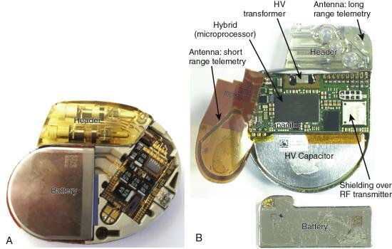
The circuitry of CIEDs is housed in a sealed case made of titanium that is airtight and impermeable to fluid (Fig. 8.1). These devices store information about the activities of the patient’s heart and information about the device itself (e.g., number of dysrhythmia episodes; provoking rhythm; dates of pacing, defibrillation, or both). The stored information is periodically retrieved and reviewed by the patient’s physician, and, if necessary, changes in the device’s settings are made. Lithium batteries are almost exclusively used in modern CIEDs. Battery life is generally 5 to 15 years but depends on type, programming, the number of times therapies are delivered, the frequency of pacing, and the number of cardiac chambers paced.
An ICD can deliver a range of therapies (also called tiered therapy), including defibrillation, antitachycardia pacing (i.e., overdrive pacing), synchronized cardioversion, and bradycardia pacing, depending on the dysrhythmia detected and how the device is programmed (Fig. 8.2). A physician determines the appropriate ICD therapies for each patient. Examples of ICD indications include patients who have experienced a sudden cardiac arrest due to ventricular tachycardia (VT) or ventricular fibrillation (VF), structural heart disease with sustained VT, or syncope caused by ventricular dysrhythmias. Patients with an ICD should notify their physician after the device fires to have it checked.

Patients should schedule regular appointments with their cardiologist for device function checks (e.g., battery status, system checks). Generally, a CIED’s battery does not suddenly fail. Instead, the battery gradually wears out, enabling elective CIED replacement. In some cases, CIED monitoring can be accomplished remotely using a device connected to the patient’s phone.
Patients with a CIED should carry their device’s information card, a current list of medications, and their physician’s name and phone number and have or wear medical alert identification. The information card can be shown if the CIED sets off a metal detector. If security personnel use a metal-detecting wand, it should not be placed over the device for more than a second because the magnet inside the wand may temporarily change the operating mode of the CIED.
Cell phones can interfere with proper CIED function because they send electromagnetic signals. Therefore, the patient should hold a cell phone to the ear farthest from the CIED. Even when turned off, cell phones should not be worn in a shirt pocket on the side of the CIED. Some CIED manufacturers use special filters in their devices to prevent cell phone interference.
ECG Pearl
Historically, cardiac implanted devices were considered a contraindication to magnetic resonance imaging (MRI). However, many newer implanted devices are classified as MRI conditional, a phrase used by the American Society for Testing and Materials to denote a product that poses no hazards to a specified MRI environment with specified conditions of use. In some cases, patients with older devices may safely undergo MRI if they are appropriately screened and their devices are reprogrammed according to standard protocols.
Pacemaker leads
Pacemaker lead systems may consist of single, double, or multiple leads. A separate lead is used for each heart chamber paced. The exposed portion of the pacing lead—the electrode—is placed in direct contact with the heart. A unipolar electrode has one pacing electrode that is located at its distal tip. The negative electrode is in contact with the cardiac tissue, and the pulse generator (located outside the heart) functions as the positive electrode. The pacemaker spike produced by a unipolar lead system is often large because of the distance between the positive and negative electrodes. Unipolar leads are less commonly used than bipolar lead systems because of the potential for pacing the chest wall muscles, and the susceptibility of the unipolar leads to electromagnetic interference.
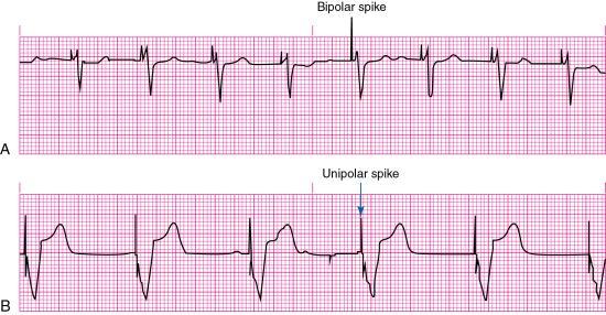
A bipolar lead system contains a positive and negative electrode at the distal tip of the pacing lead wire. Most temporary transvenous pacemakers use a bipolar lead system. However, a permanent pacemaker may have either a bipolar or a unipolar lead system. The pacemaker spike produced by a bipolar lead system is smaller than that of a unipolar system because of the shorter distance between the positive and negative electrodes (Fig. 8.3).
ECG Pearl
A leadless pacemaker consists of a self-contained generator and lead system. It is inserted through the femoral vein and into the right ventricle, eliminating the need for a chest incision and creating a pocket in the patient’s chest to house a pulse generator. First-generation leadless pacemakers provide only single-chamber ventricular pacing. The Micra Transcatheter Pacing System (Medtronic PLC, Minneapolis, MN), which is about a large vitamin capsule size, received US Food and Drug Administration (FDA) approval in 2016. The Nanostim Leadless Cardiac Pacemaker (Abbott Laboratories, Abbott Park, IL) is awaiting FDA approval.
Pacing principles
Pacing, also called pacemaker firing, occurs when the pacemaker’s pulse generator delivers energy (milliamperes [mA]) through the pacing electrode to the myocardium. As mentioned earlier, a pacemaker responds to the information received either by sending a pacing stimulus to the heart (i.e., triggering) or by not sending a pacing stimulus to the heart (i.e., inhibiting).
A fixed-rate (asynchronous) pacemaker continuously discharges at a preset rate (usually 70 to 80 impulses/min) regardless of the patient’s heart rate or metabolic demands. An advantage of the fixed-rate pacemaker is its simple circuitry, reducing the risk of pacemaker failure. However, because this type of pacemaker does not sense the patient’s own cardiac rhythm, competition between the patient’s cardiac rhythm and that of the pacemaker can result. VT or VF may be induced if the pacemaker were to fire during the T wave (i.e., the vulnerable period) of a preceding patient beat. Therefore, fixed-rate pacemakers are not often used today.
A demand (synchronous) pacemaker discharges when the patient’s heart rate drops below the pacemaker’s lower rate limit (also called the base rate), which is expressed in paced pulses per minute (ppm). For example, if the demand pacemaker were preset at a lower rate limit of 70 ppm, it would sense the patient’s heart rate and allow electrical impulses to flow from the pacemaker through the pacing lead to stimulate the heart only when the rate fell below 70/min.
Evidence of pacing can be seen as a vertical line or spike on the ECG. Capture is the successful conduction of an artificial pacemaker’s impulse through the myocardium, resulting in depolarization. Capture is obtained after the pacemaker electrode is correctly positioned in the heart; with one-to-one capture, each pacing stimulus depolarizes the appropriate chamber. On the ECG, evidence of electrical capture can be seen as a pacemaker spike followed by an atrial or a ventricular complex, depending on the cardiac chamber that is being paced (see Fig. 8.3). Mechanical capture is assessed by palpating the patient’s pulse or observing right atrial pressure, left atrial pressure, or pulmonary artery or arterial pressure waveforms.
Pacemaker modes
Pacemaker modes are characterized using a three- to five-letter code that identifies a pacemaker’s preprogrammed pacing, sensing, and response functions. The first three letters are the most helpful when providing patient care.
The first letter of the code identifies the heart chamber (or chambers) paced: O (none), A (atrial), V (ventricular), or D (dual, both atrium and ventricle). The second letter identifies the heart’s chamber where patient-initiated (i.e., intrinsic) electrical activity is sensed by the pacemaker. O (none), A (atrial), V (ventricular), or D (dual). The third letter indicates how the pacemaker will respond when it senses patient-initiated electrical activity: O (none), T (triggered, the pacemaker will initiate a pacing stimulus in response to a sensed event), I (inhibited, the pacemaker will not initiate a pacing stimulus if electrical activity is sensed), or D (dual, triggered and inhibited). The fourth letter identifies the availability of rate modulation (i.e., the pacemaker’s ability to adapt its rate to meet the body’s needs caused by increased physical activity and increase or decrease the pacing rate accordingly). A pacemaker’s rate modulation capability may also be referred to as rate responsiveness or rate adaptation. Finally, the fifth letter denotes multisite pacing (i.e., biventricular pacing or more than one pacing site in one ventricle): O (none), A (atrium), V (ventricle), or D (dual, atrium and ventricle).
Single-chamber pacemakers
A pacemaker that paces a single heart chamber, either the atrium or ventricle, has one lead placed in the heart. Atrial pacing, achieved by placing the pacing electrode in the right atrium, may be used when the SA node is diseased or damaged, but conduction through the AV junction and ventricles is normal. This type of pacemaker is ineffective if an AV block develops because it cannot pace the ventricles. An atrial demand pacemaker (AAI) senses atrial activity (i.e., P waves). When spontaneous atrial depolarization does not occur within a preset interval, the pacemaker fires and stimulates atrial depolarization at a preset rate. Atrial stimulation produces a pacemaker spike on the ECG followed by a P wave (Fig. 8.4).
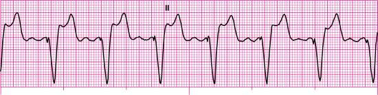
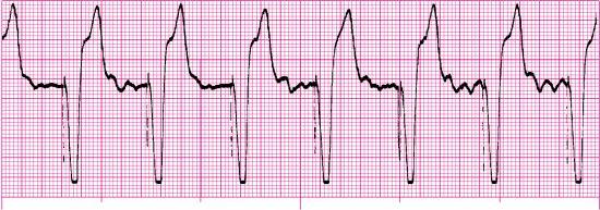
With ventricular demand pacing (VVI), the pacemaker electrode is placed in the right ventricle (V), the ventricle is sensed (V), and the pacemaker is inhibited (I) when spontaneous ventricular depolarization occurs within a preset interval. The pacemaker will fire and stimulate ventricular depolarization at a preset rate if spontaneous ventricular depolarization does not occur within this preset interval. Stimulation of the ventricles produces a pacemaker spike on the ECG followed by a wide QRS, resembling a ventricular ectopic beat (Fig. 8.5). The QRS complex is wide because a paced impulse does not follow the heart’s normal conduction pathway. A VVI pacemaker may be used for patients with atrial fibrillation and a slow ventricular response. Because a VVI pacemaker does not coordinate pacing with the patient’s intrinsic atrial rate, it can result in asynchronous contraction of the atrium and ventricle (i.e., AV asynchrony). The loss of AV synchrony can result in a loss of the atrial contribution to cardiac output (i.e., atrial kick), decreased stroke volume, and decreased cardiac output, producing a constellation of signs and symptoms known as pacemaker syndrome. Pacemaker syndrome signs and symptoms may include dizziness, acute mental status changes, dyspnea on exertion, orthopnea, fatigue, palpitations, hypotension, syncope or near-syncope, neck vein distention, and lower extremity edema.
ECG Pearl
On the ECG, P waves can appear anywhere in the cardiac cycle and have no relationship with the QRS complexes because a ventricular demand pacemaker does not sense or pace atrial activity.
Dual-chamber pacemakers
A dual-chamber pacemaker is the most common type of implanted pacemaker. It uses two leads: one lead is placed in the right atrium and the other in the right ventricle.
An atrial synchronous pacemaker (VDD) senses both atrial and ventricular activity but paces only the ventricle when a spontaneous ventricular depolarization does not occur. A VDD pacemaker is used for patients who have impaired AV conduction but an intact SA node. The presence of SA node disease is a contraindication for a VDD pacemaker.
An AV sequential pacemaker (DVI) first stimulates the right atrium and then the right ventricle but senses only the ventricle. It may be used for patients with severe sinus bradycardia. Asynchronous atrial pacing and the potential for AV asynchrony (with possible pacemaker syndrome) can occur with DVI pacing.
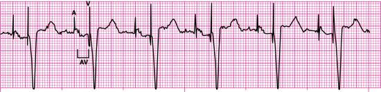
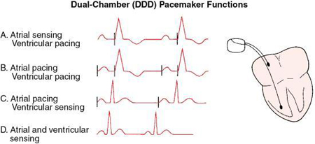
An optimal sequential pacemaker (DDD), also called a physiologic or universal pacemaker, is used when the SA node is intact but AV conduction is impaired. In DDD mode, both the atrium and ventricle are paced (D), both chambers are sensed (D), and the pacemaker has both a triggered and inhibited mode of response (D). The pacemaker is programmed to wait between atrial and ventricular stimulation, simulating the usual delay in conduction through the AV node (i.e., the PR interval). The artificial or electronic PR interval is referred to as an AV interval (Fig. 8.6). If spontaneous atrial or ventricular depolarization does not occur within a preset interval, the pacemaker fires and stimulates the appropriate chamber at a preset rate. DDD pacemaker functions are summarized in Fig. 8.7. New dual-chamber pacemakers are equipped with programmable features that enable automatic adjustment of the AV interval in response to paced versus sensed P waves and in response to the atrial rate. A DDD pacemaker can be programmed to VVI mode, depending on patient need (e.g., the development of chronic atrial fibrillation).
Biventricular pacemakers
A biventricular pacemaker has three leads—one lead for each ventricle and one lead for the right atrium. These devices use cardiac resynchronization therapy (CRT) to restore normal simultaneous ventricular contraction, thus improving stroke volume, ejection fraction, cardiac output, and exercise tolerance. CRT, which is indicated for selected patients with moderate to severe heart failure, has been shown to reduce heart failure symptoms and mortality.
Pacemaker complications
Complications of permanent pacing associated with the implantation procedure include bleeding, local tissue infection, pneumothorax, cardiac dysrhythmias, air embolism, and catheter-related thrombosis. Long-term complications of permanent pacing may include infection, heart failure, lead displacement or fracture of the pacing lead, externalization of the pacemaker generator, chamber perforation, and pacemaker-induced dysrhythmias. Problems that can occur with pacing include failure to pace, failure to capture, and failure to sense (e.g., undersensing, oversensing).
Failure to pace
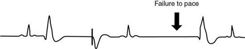
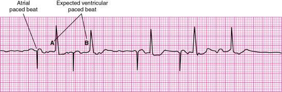
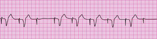
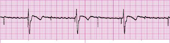
Failure to pace, also referred to as failure to fire or failure of pulse generation, is a pacemaker malfunction that occurs when the pacemaker fails to deliver an electrical stimulus at its programmed time. Failure to pace is recognized on the ECG as an absence of pacemaker spikes, even though the patient’s intrinsic rate is less than that of the pacemaker, and a return of the underlying rhythm for which pacing was initiated (Fig. 8.8). Patient signs and symptoms may include bradycardia, chest discomfort, hypotension, and syncope.
Causes of failure to pace are listed in Box 8.1. Treatment may include adjusting the sensitivity setting, replacing the pulse generator battery, replacing the pacing lead, replacing the pulse generator unit, tightening connections between the pacing lead and pulse generator, or removing the source of electromagnetic interference.
Failure to capture
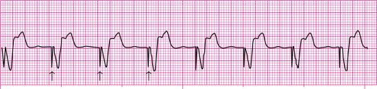
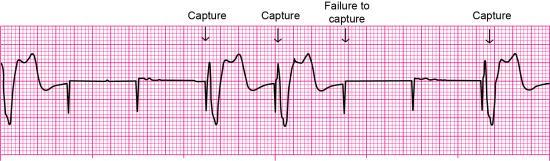
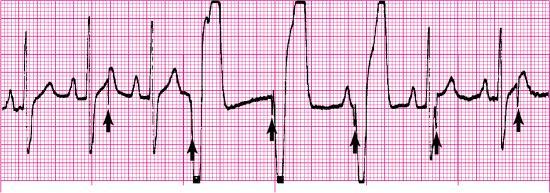
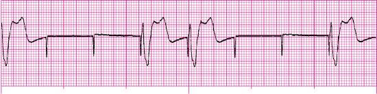
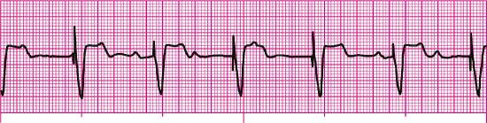
Failure to capture is the inability of the artificial pacemaker stimulus to depolarize the myocardium. It is recognized on the ECG by visible pacemaker spikes not followed by P waves (if the electrode is in the atrium) or QRS complexes (if the electrode is in the right ventricle) (Fig. 8.9). Patient signs and symptoms may include bradycardia, fatigue, and hypotension.
Causes of failure to capture are shown in Box 8.2. If the problem results from low output energy, slowly increasing the output setting (mA) until capture occurs may resolve the problem. With transvenous pacing, repositioning the patient to the left side may promote the contact of a transvenous pacing lead with the endocardium and septum.
Failure to sense
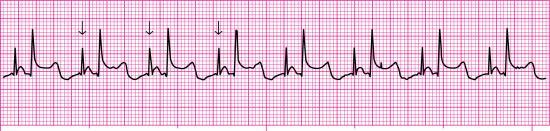
Sensitivity is the extent to which an artificial pacemaker recognizes intrinsic cardiac electrical activity. Undersensing occurs when the artificial pacemaker fails to recognize spontaneous myocardial depolarization. It is recognized on the ECG by pacemaker spikes that occur within P waves, pacemaker spikes that follow too closely behind the patient’s QRS complexes, or pacemaker spikes that appear within T waves (Fig. 8.10). Because pacemaker spikes occur when they should not, this type of pacemaker malfunction may result in pacemaker spikes that fall on T waves (i.e., R-on-T phenomenon), competition between the pacemaker and the patient’s intrinsic cardiac rhythm, or both. As a result, the patient may complain of palpitations or skipped beats.
Causes of failure to sense are shown in Box 8.3. Treatment may include increasing the sensitivity setting, replacing the pulse generator battery, or replacing or repositioning the pacing lead.
Oversensing is a pacemaker malfunction that results from inappropriate sensing of extraneous electrical signals. For example, atrial sensing pacemakers may inappropriately sense ventricular activity; ventricular sensing pacemakers may misidentify a tall, peaked intrinsic T wave as a QRS complex. Oversensing is recognized on the ECG as pacemaker spikes at a rate slower than the pacemaker’s preset rate or no paced beats even though the pacemaker’s preset rate is greater than the patient’s intrinsic rate (Fig. 8.11). Treatment includes adjustment of the pacemaker’s sensitivity setting or possible insertion of a bipolar lead if oversensing is caused by unipolar lead dysfunction.
Analyzing pacemaker function on the electrocardiogram
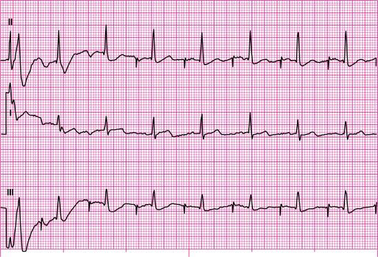
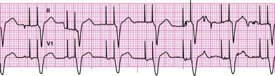
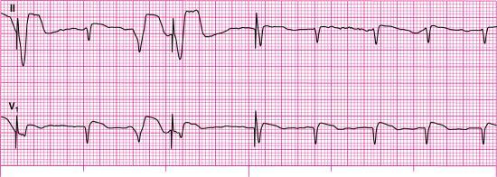
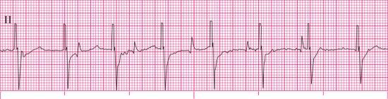
To practice analyzing pacemaker function on the ECG, let’s look at Fig. 8.12. The first step in our analysis of this rhythm strip should include identification of the patient’s underlying rhythm and its rate, if possible. Fig. 8.12 provides a look at the patient’s rhythm from two leads, and six QRS complexes are visible in each lead. Each QRS complex is preceded by one upright P wave. Based on this information, we know that the underlying rhythm is sinus in origin. The atrial and ventricular rates are regular at 65 beats per minute (beats/min).

Next, let’s look for evidence of paced activity (i.e., atrial pacer spikes, ventricular pacer spikes, or both) and evaluate the paced interval. The paced interval, also called the automatic interval, is the period between two consecutive paced events in the same cardiac chamber. Measure the distance between two consecutively paced atrial beats using calipers or paper when atrial pacer spikes are present. Because there is no pacemaker spike before any of the P waves in this rhythm strip, there is no evidence of paced atrial activity; however, a pacer spike is visible before each QRS complex.
Because paced ventricular activity is present, we must evaluate the rate and regularity of the ventricular paced interval by measuring the distance between two consecutively paced ventricular beats. The ventricular paced interval is regular at 65 pulses/min. If both atrial and ventricular pacemaker spikes were present, you would know that this patient had a dual-chamber pacemaker. Because only wide-QRS complexes are present and a pacemaker spike precedes each QRS, it is reasonable to conclude that this patient has a ventricular pacemaker. Next, compare the escape interval with the paced interval measured earlier. The escape interval is the time measured between a sensed cardiac event and the next pacemaker output. The paced interval and escape interval should measure the same; these intervals are the same in Fig. 8.12.
Next, analyze the rhythm strip for failure to pace, failure to capture, and failure to sense. Remember that the ECG will reveal an absence of pacemaker spikes at their programmed time with failure to pace. Because the pacer spikes in Fig. 8.12 occur regularly, we know that failure to pace is not present. When failure to capture occurs, pacer spikes appear regularly, but the waveforms after them are periodically absent (i.e., P waves are periodically absent if the pacing electrode is in the atrium, QRS complexes are periodically absent if the pacing electrode is in the ventricle). Because there is a 1:1 relationship between pacemaker spikes and QRS complexes in this rhythm strip, we know that 100% ventricular capture is present. When failure to sense exists, unexpected paced beats or unexpected pacer spikes are present (i.e., undersensing), or prolonged pauses are present (i.e., oversensing). Evaluation of the waveforms and pacer spikes in Fig. 8.12 reveals no unexpected beats, no unexpected pacer spikes, and no prolonged pauses; thus, failure to sense is not present.
Before we complete our interpretation, we should briefly discuss what looks like ST-segment elevation in this rhythm strip. The QRS complexes are negatively deflected (i.e., a QS configuration), and the ST segments and T waves are in the opposite direction of the last portion of the QRS complex. As you have learned, these findings are expected in ventricular rhythms and left bundle branch block (LBBB). Think of a ventricular paced beat as a manmade LBBB. When LBBB occurs, the electrical impulse travels down the right bundle branch, depolarizes the right ventricle, and then spreads through the myocardium to depolarize the left ventricle. Pacemakers are most often introduced into the right ventricle. When a pacemaker fires, it sends its impulse into the right ventricle, which depolarizes, and the impulse is spread through the myocardium to depolarize the left ventricle. Therefore, just as with LBBB, ventricular paced rhythms may exhibit ST-segment elevation that is not the result of any infarct-related causes because ventricular depolarization is abnormal.
ECG Pearl
Careful correlation of the patient’s ECG, clinical presentation, and the results of other diagnostic studies are essential.
In summary, we will identify the rhythm strip in Fig. 8.12 as a sinus rhythm with a ventricular pacemaker and 100% capture with a paced interval of 65 pulses/min. If the patient’s intrinsic rate differed from that of the pacemaker, we would include the paced rate in pulses per minute and the patient’s heart rate in beats per minute in our rhythm description.
Stop & review
Matching
Match the terms below with their descriptions by placing the letter of each correct answer in the space provided.
- a. AV interval
- b. Oversensing
- c. Dual chamber
- d. Inhibition
- e. Demand
- f. Failure to capture
- g. Lower rate limit
- h. Pacemaker spike
- i. Failure to pace
- j. Rate modulation
- k. Pulse generator
- l. Undersensing
- m. Threshold
- n. Paced interval
- o. Fixed rate
- ____ 1. A vertical line on the ECG that indicates the pacemaker has discharged
- ____ 2. A pacemaker malfunction that occurs when the artificial pacemaker fails to recognize spontaneous myocardial depolarization
- ____ 3. A pacemaker malfunction that occurs when the artificial pacemaker stimulus is unable to depolarize the myocardium
- ____ 4. The period between two consecutive paced events in the same cardiac chamber
- ____ 5. This type of pacemaker uses an atrial and ventricular lead
- ____ 6. An artificial PR interval
- ____ 7. This type of pacemaker discharges only when the patient’s heart rate drops below the preset rate for the pacemaker
- ____ 8. The ability of a pacemaker to increase the pacing rate in response to physical activity or metabolic demand
- ____ 9. This type of pacemaker continuously discharges at a preset rate regardless of the patient’s intrinsic activity
- ____ 10. A pacemaker malfunction that results from inappropriate sensing of extraneous electrical signals
- ____ 11. The power source that houses the battery and circuitry for regulating a pacemaker
- ____ 12. The rate at which the pacemaker’s pulse generator initiates impulses when no intrinsic activity is detected; expressed in pulses per minute
- ____ 13. The minimum amount of voltage (i.e., milliamperes) needed to obtain consistent capture
- ____ 14. Pacemaker response in which the output pulse is suppressed when an intrinsic event is sensed
- ____ 15. A pacemaker malfunction that occurs when the pacemaker fails to deliver an electrical stimulus at its programmed time
Pacemaker rhythms—practice rhythm strips
For each of the following rhythm strips, identify the patient’s underlying rhythm (if possible); determine the presence of atrial paced activity, ventricular paced activity, or both; and then analyze the rhythm strip for pacemaker malfunction. All rhythm strips were recorded in lead II unless otherwise noted.


Stop & review answers
Matching
Practice rhythm strip answers
Note: The rate and interval measurements provided here were obtained using electronic calipers.
- 16. Fig. 8.13
- 17. Fig. 8.14
- 18. Fig. 8.15
- 19. Fig. 8.16
- 20. Fig. 8.17
- 21. Fig. 8.18
- 22. Fig. 8.19
- 23. Fig. 8.20
- 24. Fig. 8.21
- Atrial paced activity? No
- Ventricular paced activity? Yes
- Pacemaker malfunction? Yes—failure to capture; three of seven paced impulses captured (the first complex is not counted because the pacer spike before the complex is not visible)
- Interpretation: Ventricular paced rhythm at 79 pulses/min with failure to capture
- 25. Fig. 8.22
- 26. Fig. 8.23
- 27. Fig. 8.24
- 28. Fig. 8.25
- 29. Fig. 8.26
- 30. Fig. 8.27
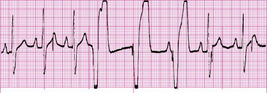
- Atrial paced activity? No
- Ventricular paced activity? Yes
- Pacemaker malfunction? Yes—failure to sense (undersensing)
- Interpretation: Sinus rhythm at 88 beats/min with a ventricular pacemaker and pacemaker malfunction (undersensing); note the pacer spikes in the T waves of the second and eighth beats from the left