19: Contemporary Straight Wire Biomechanics
Antonino G. Secchi; Jorge Ayala Puente
It is not only the appliance system you have, but how you use it. Antonino Secchi
The straight wire appliance (SWA) was developed and introduced by Lawrence Andrews in 19701 with the idea of having an orthodontic fixed appliance that would enable the orthodontist to achieve the “6 keys” of normal occlusion2 in the vast majority of cases in an efficient and reliable fashion.
Even though the SWA is over 50 years old and is in widespread use, a review of some of the original concepts on which the SWA was designed and the evolution it has gone through are fundamental to better understand the beauty of this appliance and the treatment mechanics, which we then discuss.
Straight wire appliance design and values
There are a few features that need to be present in an appliance for it to be considered a true SWA.3 First, each bracket has to be tooth specific and have built-in torque, tip, in/out, and (for the molars) proper offset. Second, the torque has to be built in the base of the bracket, not in the face, and the tip in the face of the slot. These prerequisites are very important to achieve proper alignment of the center of the slot, the center of the base, and the reference point (middle of the clinical crown occlusogingivally along the facial long axis of the crown) for all teeth at the completion of treatment. This is the only way that the desired built-in features can be properly transferred from the bracket to the tooth. Third, the base of the bracket must be contoured mesiodistally and occlusogingivally. This has been referred to as a “compound contour base,” and it allows the bracket to firmly adapt to the convexities of the labial surface of each tooth, helping the orthodontist achieve an optimal bracket placement.
Although Andrews thought his appliance could be used to treat a large variety of cases, he introduced a series of additional brackets with different degrees of overcorrection to account for undesired tooth movement that would occur specifically when sliding teeth in extraction cases. For example, if a maxillary canine had to be moved distally, because Andrews uses round stainless steel wires to slide teeth through, the canine most likely would tip and rotate distally. Therefore he introduced more mesial tip and rotation to the canine bracket. Andrews then came out with a line of overcorrected brackets, which he first called extraction brackets3 and then translation brackets.4 Andrews’ complete bracket system (standard and translation brackets) was less popular than expected, partly because of the large bracket inventory needed to satisfy his treatment mechanics. However, in the mid-1970s, Ronald H. Roth took the Andrews SWA and combined some of the standard bracket prescription values with some of the overcorrected values found in the translation bracket prescription to create the “Roth setup.”5 The Roth setup became the most popular SWA prescription in the world. Roth realized that because the size of the brackets at that time caused bracket interferences, it was virtually impossible to place each tooth in its final ideal position. Also, he observed that when appliances were removed, teeth would rebound and settle. Therefore he slightly overcorrected some of the original Andrews values to allow teeth to properly settle in the ideal final position after removal of the appliances. After the Roth prescription, a great number of clinicians came out with small variations to either the Andrews prescription or the Roth prescription. Most of these changes were done for a commercial purpose, to compensate for unknown errors in bracket position, bracket slot size variation, or to suit a particular orthodontist’s type of mechanics.
Today, there are a large number of preadjusted appliances wrongly called SWAs only because they have built-in torque, tip, and in/out. However, if they are not manufactured with the features specified earlier, the appliance will not transfer the built-in information correctly to the teeth. Therefore selecting the proper appliance is paramount when using an SWA.
Straight wire appliance and self-ligation
Both of the authors of this chapter use a self-ligating bracket (SLB) system, and, consequently, some of the concepts on mechanics that will be reviewed later take advantage of such appliance systems. Therefore, even though self-ligation is the subject of Chapter 20 in this textbook and thus is extensively reviewed, it is important to point out a few aspects of this type of appliance that will allow the reader to better understand the information provided in this chapter.
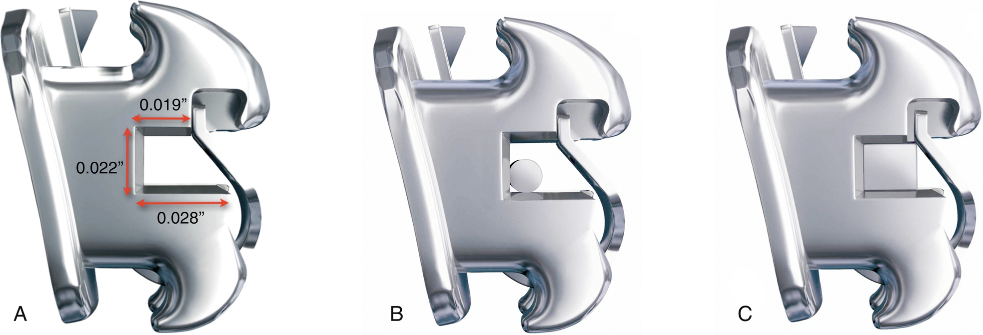
Self-ligating brackets have been classified as “active” or “passive” depending on the behavior of the gate or clip on the archwire. Active SLBs have a clip with a spring effect that exerts pressure on the archwire, pushing it onto the base of the bracket’s slot. This pressure is based on the archwire size and/or bracket and archwire configuration (Fig. 19.1). On the other hand, passive SLBs have a gate that passively opens and closes without exerting pressure on the archwire. Passive SLBs also have been described as tubes.6 Today it is known that active SLBs have some important advantages over passive SLBs. In active SLBs, as stated earlier, one can manage the amount of activity that the clip will have by the size of the archwire. For instance, at the beginning of treatment when less resistance to sliding is desirable and usually the archwire of choice is a small, round thermal-activated wire, active and passive brackets have shown equal behavior.7 As treatment progresses, an increased resistance to sliding is desired to achieve proper torque expression. At this stage of treatment, passive SLBs have demonstrated poor behavior compared with active SLBs.8,9 It is important to remember that the active clip is a very important feature of active SLBs, and therefore the quality of the clip will determine to some extent how well the bracket will work. Substantial differences have been shown in clip performance when some SLB clips lose an important percentage of force during treatment. In addition, it is important to note that not every active available SLB is a true SWA. The SLB must have all the other features mentioned earlier to be a true SWA.
Optimal Bracket Placement
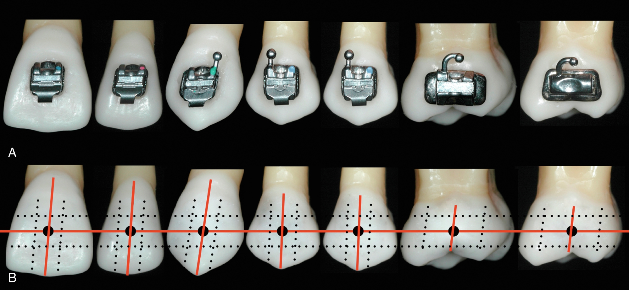
Assuming we have the right appliance, the next most important factor when working with an SWA is bracket position. This is where the orthodontist’s skill is of great value. With techniques that require bending of the wire, the quality and precision of each bend will determine to some extent the quality of the final result, as the precision of bracket placement will do it when using an SWA. When using an SWA, you “start finishing” your case the day you place the brackets. This is why an important percentage of problems that orthodontists experience toward the end of active treatment—such as marginal ridge discrepancies, difficulty correcting rotations, lack of root parallelism, and, ultimately, less than ideal tooth position—are caused by incorrect bracket placement. As Andrews described 50 years ago, the brackets should be placed at the facial axis (FA) point. The FA point is the middle of the clinical crown occlusogingivally and mesiodistally, following the long axis of the crown, for each tooth in the mouth (Fig. 19.2).
Because all the brackets are working at the same time through the wire, one misplaced bracket will automatically affect the adjacent brackets. If more than one bracket is misplaced, the problem will increase and become more noticeable as the wire sequence progresses. This issue, if not corrected, can prevent the orthodontist from finishing the case in an optimal and efficient way.
Because we have limited space in this chapter, we will not describe the specific bracket position for each individual tooth but rather focus on the teeth that usually cause more problems for clinicians. It is important to emphasize the following concepts:
- • Andrews demonstrated that trained clinicians are able to place brackets consistently at the FA point without any aids but their own eyes.
- • The use of any gauge as an aid to position the brackets is not necessary; in fact, to use any predetermined height from the incisal edge to locate the brackets, as some orthodontists advocate, is wrong and negates the use of the FA point, which is one of the fundamentals of the proper management of the SWA. However, you have to take into account shorter crowns caused by excessive gingival tissue, worn teeth, or fractured teeth that eventually will be restored, so in some of these situations, the brackets will look more incisally or gingivally than they should be.
- • To fully level and express the torque, tip, and in/out of each bracket, the slot of the bracket has to be filled, which requires 0.021- × 0.025-inch stainless steel wire. It is important to know that a 0.019- × 0.025-inch stainless steel wire has about 10.5 degrees of play on a 0.022-inch bracket slot.10 However, this is not the case when using active SLBs, as explained later in the chapter.
Although the FA point and long axis of clinical crowns are key to bracket position, a few specific considerations facilitate bracket placement on certain teeth, such as the upper and lower canines, upper and lower first molars, and sometimes upper lateral incisors and premolars.
- • Canines: The long axis of the upper and lower canines, which is also the most convex part of the labial surface, is located more mesial than the true mesiodistal center of the tooth; therefore, the FA point looks a little bit more mesial than the dead center of the tooth. If you err and place the bracket on the center of the crown mesiodistally, the canine will rotate mesially.
- • Molars: The landmark that Andrews used as the long axis of the clinical crown for the molar is the buccal groove. The FA point then lies along the buccal groove, midway occlusogingivally (see Fig. 19.2). It is important to realize that the center of the tube mesiodistally should be in agreement with the FA point. As some manufacturers have reduced the mesiodistal length of tubes, orthodontists have started positioning tubes too far mesial, resulting in distal overrotation of the molars.
- • Upper lateral incisor: After the third molars, the upper lateral incisors are the teeth with more problems involving size and shape. This makes it difficult to determine the long axis of the crown from the buccal. It is wise to use a mirror to look at the lingual surface of the incisor and then extend the long axis of the clinical crown from the lingual to the buccal.
- • Premolars: Usually premolars, specifically second premolars, represent a challenge at the time of bonding because of a lack of direct vision. In these cases, it is advisable to look with a mirror from the occlusal and the buccal to locate the FA point and the long axis of the clinical crown.
Both authors think that indirect bonding can be of great help to better position the brackets, specifically on premolars and molars, decreasing the need for fine tuning and rebonding of brackets to improve their position during treatment.
Treatment Mechanics
For didactic purposes, treatment mechanics usually has been divided into different stages, from three to seven depending on authors’ preference. Simplicity is of paramount importance when teaching; therefore, all the mechanics to be accomplished in our orthodontic treatments with the SWA can be divided into three stages: stage 1, leveling and aligning; stage 2, working stage; and stage 3, finishing stage.
During each of these stages, there are specific movements of teeth that will occur and specific goals that have to be achieved before continuing to the next stage of treatment. It is important to emphasize that both the treatment outcome and its efficiency will be greatly improved if the orthodontist follows these stages. The following stages of treatment mechanics, with their respective wire sequence, have been tailored for active SLBs, although they can be applied to any SWA.
Stage 1: Leveling and Aligning
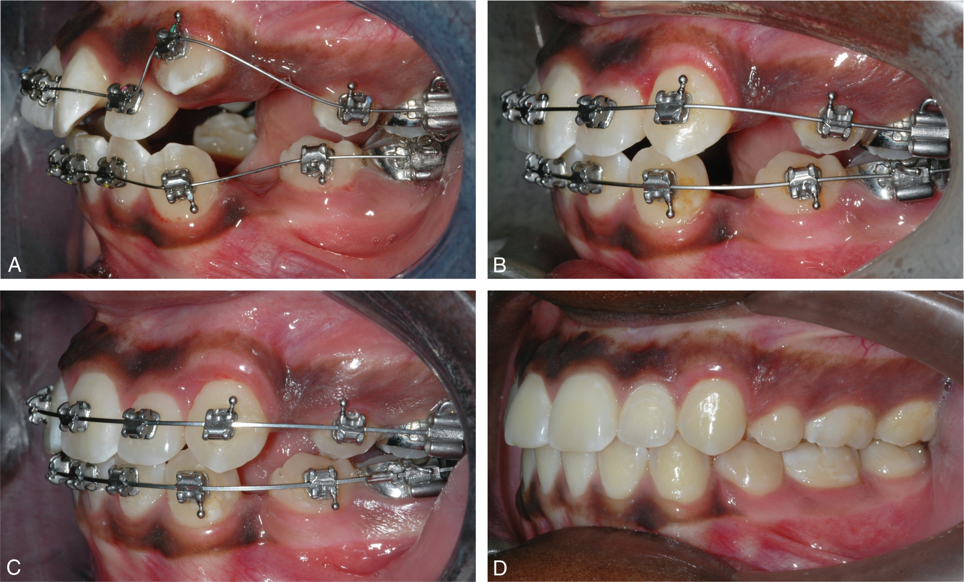
Leveling and aligning is a complex process in which all the crowns are moving at the same time and in different directions. As the teeth level and align, reciprocal forces between them develop, which can be of great help to guide the movements to our advantage. Then, when possible, all teeth should be engaged from the beginning to obtain maximum efficiency of tooth movement. Usually at this stage, round small-diameter thermal-activated wires, such as a 0.014 inch for severe crowding or a 0.018 inch for moderate to minimum crowding, are preferred in a 0.022 bracket setup. In cases that required retraction of the incisors, it is recommended to cinch the wire back of the second molar tube or to place crimpable stops to avoid undesirable movement of the wire, causing discomfort to the patient. These round wires can be in place for as long as 8 to 12 weeks before proceeding to the next wire, which usually is a 0.020- × 0.020-inch thermal-activated wire. This wire is a low-deflection thermal-activated wire that works very well as a transitional wire from stage 1 to stage 2. The 0.020- × 0.020-inch wire corrects most of the rotations left by the previously used round wires and provides more stiffness to start leveling the curve of Spee and therefore flatten the occlusal plane. It is important to notice that even if you could start treatment with a rectangular or square thermal-activated low-deflection wire, with the assumption of saving time and providing torque from the beginning of treatment, this is absolutely not recommended because it may cause loss of posterior anchorage. This happens for two main reasons: first, the only teeth with positive labial crown torque are the maxillary central and lateral incisors, and second, the mesial crown tip of the maxillary and mandibular canines is rather large. Therefore, if we start treatment resolving the crowding with a rectangular or square wire, we are providing labial crown torque to the maxillary incisors and mesial crown tip to canines, which will increase our anchorage in the front part of the arch, facilitating the loss of anchorage in the posterior part of the arch. This is critical in cases in which the treatment plan calls for maximum retraction of the maxillary or mandibular incisors (or both). In these cases, the use of a 0.020-inch thermal-activated wire can be better indicated than the 0.020- × 0.020-inch wire and thus will not provide torque and the tip effect on the canines will be minimal. This allows the molar and premolars to level, align, and upright, which will produce a “lasso” effect on the incisors that will upright and sometimes even retract them (Fig. 19.3).
The 0.020- × 0.020-inch wire will make the clip of the SLB active and thus start delivering torque; nonetheless, its strength is not sufficient to compromise the anchorage that has already been created with the round wires. Usually, after 8 to 10 weeks with the 0.020- × 0.020-inch wire, the stage 1 of leveling and aligning is finished, and in the authors’ opinion, it is the first time to evaluate bracket placement and reposition brackets as necessary. Then we are ready to start stage 2, the working stage.
The following are the movements we should expect and goals we should accomplish when leveling and aligning, before starting stage 2:
- • Teeth move individually.
- • It is mainly crown movement.
- • Molars and premolars derotate and upright distally.
- • Incisors are upright and sometimes even retract.
- • Start building posterior anchorage.
- • Before proceeding to stage 2, check bracket position (gross errors) and reposition brackets as indicated.
The following are the most common wires and sequence used at stage 1 of treatment:
- • Mainly round, small-diameter, superelastic wires (ideally thermal activated)
- • Square or rectangular superelastic wires to correct remaining rotations and level the occlusal plane (Tables 19.1 and 19.2)
Types of Wires, Size, and Sequence Suggested for Stage 1 of Treatment Mechanics in Cases with Moderate to Severe Crowding Severe to moderate crowding STM1 Type Size (Inches) Sequence Niti thermal activated 0.014 0.014 0.018 Niti thermal activated 0.018 × 0.018 0.018 0.020 × 0.020 0.019 × 0.025 0.020 × 0.020 STM, Stage of treatment mechanics.
Types of Wires, Size, and Sequence Suggested for Stage 1 of Treatment Mechanics, in Cases with Mild Crowding Mild crowding STM1 Type Size (Inches) Sequence Niti thermal activated 0.014 0.018 0.018 Niti thermal activated 0.018 × 0.018 0.020 × 0.020 0.020 × 0.020 0.019 × 0.025 STM, Stage of treatment mechanics.
Stage 2: Working Stage
This stage of treatment is the one on which we will spend more time. At this stage, the maxillary and mandibular arches are coordinated and proper overbite and overjet are achieved, Class II or Class III are corrected, maxillary and mandibular midlines are aligned, extraction spaces are closed, and maxillary and mandibular occlusal planes are leveled. Although most of these corrections happen simultaneously, we will describe them separately for didactic reasons so key points can be emphasized.
Arch coordination
The maxillary and mandibular archwires must be coordinated to obtain a stable occlusal intercuspation and proper overjet. In an ideal intercuspation of a Class I, one-tooth to two-teeth occlusal scheme, the palatal cusps of the maxillary molars should intercuspate with the fossae and marginal ridges of mandibular molars, the buccal cusp of the mandibular premolars should intercuspate with the marginal ridges of the maxillary premolars, and the mandibular canines and incisors should intercuspate with marginal ridges of the maxillary canines and incisors. If this occlusal scheme occurs, it will then provide an overjet of 2 to 3 mm all around the arch from second molar to second molar. Then the maxillary archwire must be 2 to 3 mm wider than the mandibular archwire. The archwire coordination is done with the stainless steel wire. Even if they come preformed, the clinician should not rely on them and should check them before insertion.
Another important aspect of arch coordination is the effect that it has on the vertical dimension and the sagittal dimension. Arch coordination is a transverse issue. The maxillary teeth should be upright and centered in the alveolar/basal bone and coordinated with the mandibular teeth, which should also be upright and centered in the alveolar/basal bone to obtain a proper intercuspation. Often, this is not the case, and we find maxillary molars buccally inclined, also referred as an accentuated curve of Wilson, which can produce contacts between the palatal cusp of maxillary molars and the inclines or even the cusps tip of the mandibular molars. This decreases the overbite and sometimes produces even an open bite (vertical problem), which in turn can produce a downward and backward movement of the mandible (sagittal problem). This phenomenon is due to the lack of palatal crown torque of the maxillary molars. Depending on the amount of palatal crown torque needed for the maxillary molars to level the curve of Wilson, we suggest three solutions:
- 1. For minor problems with torque, we can wait until the finishing stage, when a larger size wire (0.021- × 0.025-inch stainless steel) can be used to fill the slot and deliver more torque to the molars.
- 2. For moderate problems with torque, we can add palatal crown torque to the working wire.
- 3. For severe problems with torque, the use of a transpalatal bar (TPB) is suggested. A TPB can be used to easily place and deliver palatal crown torque to maxillary molars (Fig. 19.4).
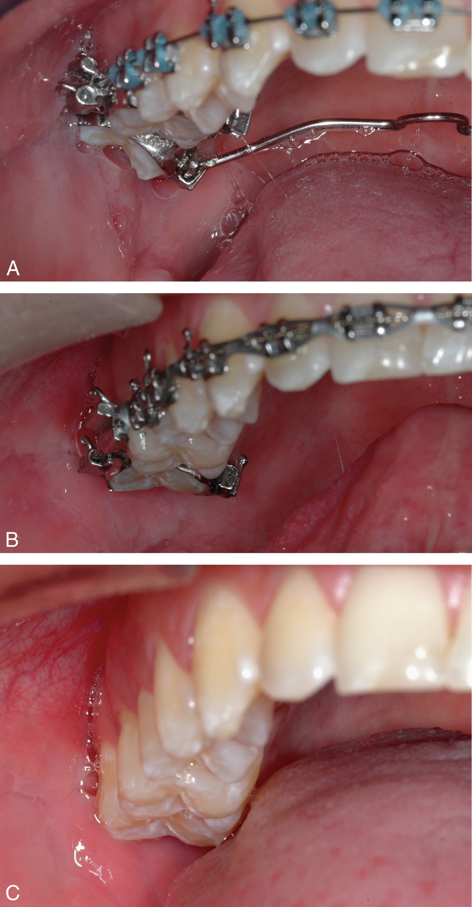
Fig. 19.4 A sequence of a maxillary second molar severely tipped to the buccal corrected with a transpalatal bar. A, Initial. B, After correction is done. C, Finished case.
Overbite and overjet correction
An optimal overbite–overjet relationship does not have to be a certain predetermined number of millimeters. More important is the functional relationship they have. This means that the overbite–overjet should be compatible with a mutually protected occlusal scheme and thus allows for a proper anterior guidance in protrusion and lateral excursive movements. Although, as already discussed, the number of millimeters is less important than the function, we find that an optimal overbite is usually around 4 mm and an optimal overjet is 2 to 3 mm. When diagnosing and treatment planning overbite–overjet problems, it is important to take the following key points into consideration: arch space management, position of the mandible in centric relation, and relationship of the upper and lower incisors with the lips. Arch space management is important to understand because the SWA tends to flatten the curve of Spee, which requires space in the arch. If not enough space is available or created, the incisors will procline, increasing the arch perimeter. This incisor proclination will also decrease the overbite and may help, if it only occurs in the lower arch, to decrease the overjet. Flattening the maxillary and mandibular occlusal planes by proclining the incisors can be of help in deep bite cases (Fig. 19.5). When the incisors are not allowed to procline, space in the arch must be created. This is specifically important to avoid periodontal problems in cases with thin bone surrounding the incisor area (see Chapter 26). Advanced diagnostic imaging tools, such as cone-beam computed tomography (CBCT), could be of great help to precisely identify the condition of the bone in this area. Up to 4 to 6 mm can be created with interproximal reduction of teeth, usually done on the incisors and less often the canines and premolars. If more than 6 mm of space is required, extraction of premolars could be indicated.
Another important factor to consider when evaluating overbite–overjet problems is the position of the mandible. Often, differences between a maximum intercuspation (MIC) and centric relation (CR) can produce significant differences in the overbite–overjet relationship. This can be clearly seen in Fig. 19.6, in which what looks like a normal overbite–overjet relationship in MIC is an anterior open bite in CR. In this case, as the mandible rotates close in CR, a primary contact found at the second molar keeps the bite open in the anterior, decreasing the overbite and preventing the mandible achieving a more stable occlusal scheme.
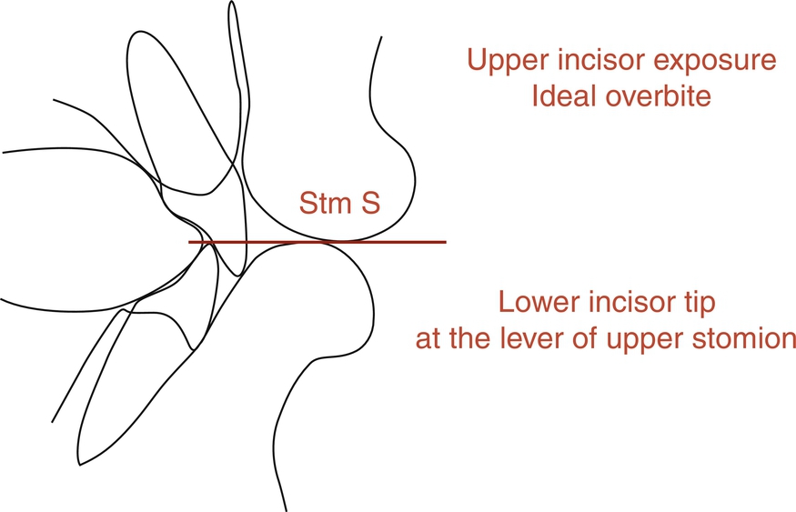
Last, but by no means the least important, is the sagittal and vertical relationship of the maxillary and mandibular incisors with the lips. In an open bite case, should the molars be intruded or should the incisors be extruded? In a deep bite case, should the maxillary incisors, the lower, or both be extruded? These basic but very important questions can be answered through an understanding of the optimal relationship of the incisors with the lips. According to contemporary esthetic trends and taking into account the aging process, for adolescents and young adults, the maxillary incisors should have, at rest, an exposure of about 4 mm beyond the most inferior point of the upper lip known as the upper stomion. As explained earlier, an optimal functional overbite should be about 4 mm. Now, if the last two concepts are put together, the incisal edge of the lower incisors should be at the same level with the most inferior point of the upper lip. Therefore any vertical change of the incisors will affect not only the function through changes of the anterior guidance but also the esthetics through the amount of tooth exposure. These anterior functional and esthetic references, explained by Ayala as the “upper stomion concept” (Fig. 19.7), will help the clinician to determine the best strategies to correct overbite–overjet problems and will be of special importance for planning cases involving orthognathic surgery.
Closing extraction spaces
Usually after leveling and aligning, the extraction spaces left are smaller than at the beginning of treatment because some of the space has been taken to unravel the initial crowding and to upright the maxillary and mandibular incisors, as described earlier in this chapter. In addition, the maxillary and mandibular occlusal planes should be leveled, and the six anterior teeth should be consolidated into one unit. Then, to efficiently close the remaining spaces, achieving the desired functional and esthetic goals, we need to determine the anchorage requirement. This will allow us to know which teeth should be moved more mesially or distally and therefore to choose the appropriate mechanics. We think that one of the easiest ways to determine the anchorage requirement is to perform a visual treatment objective (VTO). The VTO is a cephalometric exercise in which the patient’s cephalometric tracing is modified to achieve the desired end-of-treatment result, and then, by superimposing both tracings, the movements that need to occur to obtain that result can be visualized. The VTO is not a formula or equation that will determine or impose a specific type of treatment but rather an exercise in which we take into account our experience gathered from other similar cases, an estimation of the growth the patient will have during treatment, the patient’s biotype and soft tissue characteristic, and so on to more accurately plan treatment in our cases and have a visual representation of it. Thus, after the VTO has been performed, the anchorage requirement can be minimum, medium, or maximum. Before describing each one of these anchorage situations, it is important to indicate the wires and auxiliaries used at this stage. In our mechanics, we used to use a double keyhole loop (DKH) archwire, but now we prefer to use a straight wire with hooks and Niti thermal-activated coils. Both of these types of wires are stainless steel and can be either 0.019- × 0.025-inch or 0.021- × 0.025-inch, depending on the anchorage situation. The Niti thermal-activated coils can be light (100 g), medium (150 g), or heavy (200 g). In addition, when the anchorage situation calls for it, we use TPBs and temporary anchorage devices (TADs).
Double keyhole loop activation
The DKH archwire can be activated in two different ways. It can be pulled from the distal side of the first or second molar, so as to open the loops 1 mm, and then cinched back to keep the loops open. As the loops close, the teeth come together, closing the space. A different activation method is to open the loops 1 mm and then use a stainless steel ligature to ligate the distal loop to the hook of the first or second molar tube, with sufficient tension to keep the loops open. As the loops tend to close, the ligature will exert force on the molar tube, and the teeth will come together. In either manner of activation, changes in wire size and place of activation will determine the type of anchorage obtained.
Niti thermal-activated coil activation
Niti thermal-activated coils come in three different strengths: 100 g (blue dot), 150 g (yellow dot), and 200 g (red dot). It is the authors’ preference to use the 150-g Niti thermal-activated coil. These coils deliver the same force independent of the amount of activation. In our mechanics, we usually crimp a surgical type of hook distal of the canine from which a Niti thermal-activated coil is engaged all the way to the hook of either the first or second molar. If a surgical hook is not available, the Niti thermal-activated coil can be engaged to the hook of the canine bracket. This situation requires the six front teeth to be tied together with either an elastomeric chain or a stainless steel ligature so they act as a unit.
Minimum anchorage
In a minimum anchorage situation, molars will be moved mesially to close the remaining extraction spaces. We often use a 0.021- × 0.025-inch wire. This wire will express the buccal crown torque of the maxillary incisors and the mesial tip of the canines. In the mandible, this wire will express the mesial tip of the canine. This situation increases the anchorage in the anterior part of the mouth because it would be more difficult to retract or even tip back the anterior teeth while moving the molars forward. Probably the most important feature of this wire is its stiffness, which prevents de-leveling the occlusal plane as molars come forward to close the space. The activation of the DKH or the Niti thermal-activated coils must be done from the first molars. Then, after the first molar has been moved forward as desired, the second molar can be activated and moved forward, too. Often, though, this is not required because the second molars will travel forward as we move the first molars, and then the space remaining between the first and second molars will be very small and easily closed with an elastomeric chain.
Medium Anchorage
This is the most common anchorage situation encountered in our cases. Medium anchorage means that the remaining spaces should be closed reciprocally. For this situation, we use a 0.019- × 0.025-inch wire. The activation of the DKH or Niti thermal-activated coils is done, most of the time, from the first molar. However, it can also be done from the second molars, depending on how the case is progressing. The bone and attachment apparatus are not the same for every patient, and therefore the response to the closing mechanics could differ among cases. Then a clinical examination of the overbite–overjet, canine and molar relationship, and facial esthetics should be done at each visit to evaluate any changes in activation that may be required. This should not take any extra time because the activation of a DKH or Niti thermal-activated coil is a rather easy procedure.
Maximum anchorage
In a maximum anchorage situation, most of the remaining space left after leveling and aligning is closed because of distal movement of the anterior teeth. We use a 0.019- × 0.025-inch wire. The DKH or Niti thermal-activated coil is activated from the second molars. Although not frequently required in our mechanics, auxiliaries to enhance posterior anchorage such as TPB, TADs, or extraoral force (headgear) can be used as needed.
Intermaxillary elastics
Discretion is a good word to describe the use of intermaxillary elastics. We use them and like them, but it is important to understand how they are used to avoid problems. We do not use intermaxillary elastics in the following situations:
- 1. Round wires
- 2. Initial leveling and aligning, low-deflection wires
- 3. To a terminal tooth, last tooth in the arch
- 4. In the anterior part of the mouth to close open bites
- 5. In the posterior part of the mouth to correct crossbites
- 6. For an extended time
We use intermaxillary elastics in the following situations:
- 1. At the working and finishing stages
- 2. On square or rectangular stainless steel wires
- 3. On the buccal side of the mouth, short Class II or III, or triangular verticals
The three types of intermaxillary elastics we commonly use are  -inch 4-oz, 6-oz, and 8-oz elastics and
  -inch 4 oz, 6 oz, and 8 oz. Short means, in a Class II, for instance, from the maxillary canine to the mandibular second premolar in a nonextraction case and to the first mandibular molar in an extraction case.
The following are the movements we should expect and goals we should accomplish at the working stage before starting stage 3:
- 1. Movement of group of teeth in all planes of the space: sagittal, vertical, and transverse
- 2. Overjet–overbite correction
- 3. Class II and III correction
- 4. Close all remaining extraction spaces, aligning maxillary and mandibular midlines
- 5. Finish leveling the occlusal plane
- 6. Arch coordination
The following are the most common wires and sequence used at stage 2 of treatment:
- 1. In nonextraction cases, a 0.019- × 0.025-inch stainless steel wire. Reverse curve of Spee can be manually added to the wire if needed.
- 2. In extraction cases, either a 0.019- × 0.025-inch or a 0.021- × 0.025-inch stainless steel wire depending on the anchorage requirement, as previously explained (Tables 19.3 and 19.4).
Types of Wires, Size, and Sequence Suggested for Stage 2 of Treatment Mechanics in Nonextraction Cases Nonextraction STM2 Type Size (Inches) Sequence (inches) SW stainless steel 0.019 × 0.025 Niti thermal activated 0.021 × 0.028 0.019 × 0.025 Reverse curve stainless steel 0.019 × 0.025 STM, Stage of treatment mechanics: SW, straight wire.
Types of Wires, Size, and Sequence Suggested for Stage 2 of Treatment Mechanics in Extraction Cases Extraction STM2 Type Size (inches) Sequence SW stainless steel with hooks 0.019 × 0.025 0.021 × 0.025 Or Depends on anchorage requirement DKL stainless steel 0.019 × 0.025 0.021 × 0.025 DKL, Double key loops; STM, stage of treatment mechanics; SW, straight wire.
Stage 3: Finishing Stage
At this stage, to place each tooth on its ideal position and level the occlusal plane, full bracket expression is desired; thus a larger wire such as a 0.021- × 0.025-inch or a 0.022- × 0.028-inch stainless steel may be required. In our experience using an active SLB with the clip pushing and sitting the wire onto the slot, often optimal bracket expression is achieved after a 0.019- × 0.025-inch stainless steel wire has been in place for a few months. This is especially true in nonextraction cases with an average curve of Spee. However, in some cases, the size and stiffness of a 0.021- × 0.025-inch or 0.022- × 0.028-inch stainless steel are indicated, such as in cases with a deep curve of Spee, extraction cases that have required an important amount of tooth movement, and cases that required significant labial crown torque of maxillary incisors such as Class III camouflage cases and Class II, division 2 cases. When the maxillary and mandibular occlusal planes are leveled and all the bracket slots are aligned, bracket position should be carefully checked for minor correction of tooth position, and then the second time of debond and rebond should be done. If mounting analog models or digital models are part of the clinician protocol, at this point in treatment that could be done to better visualize the intercuspation of the posterior teeth, which is sometimes difficult to do clinically. The last wire we use is a stainless steel multibraided 0.019- × 0.025-inch archwire. Although this wire is large enough to maintain the tip, torque, and offset of each tooth, its resilience permits both minor bracket repositioning and “end of treatment” optimal intercuspation. It is important to notice that at this point in treatment, all the appliance interferences should be removed using a finishing carbide burr on a high-speed handpiece. With a thin articular paper, all contacts must be checked. Only tooth–tooth contacts should be allowed. All bracket, tube, or band contacts must be removed to allow proper settling. Vertical triangular -inch elastics, either 6 oz or 8 oz, are used to achieve proper intercuspation. These vertical elastics should not be used with the braided wire for more than 6 weeks to avoid rolling premolars and molars lingually, which can be detected not from the buccal but rather from the lingual, where premolars and/or molars will not be contacting. Finally, before removing the appliance, a complete assessment of the occlusal end-of-treatment goals should be performed. We strive to finish our cases with a static occlusal scheme compatible with the six keys of optimal occlusion described by Andrews1 and a dynamic mutually protected occlusal scheme in centric relation described by Roth11 (Table 19.5).
| STM3 Type | Size (Inches) | Sequence |
|---|---|---|
| SW stainless steel | 0.021 × 0.025 | SW stainless steel |
| 0.021 × 0.028 | ↓ | |
| Braided stainless steel | 0.019 × 0.025 0.021 × 0.025 | Braided stainless steel; either size is fine |
SW, Straight wire; STM, stage of treatment mechanics.
Future directions
Although alternative SWA prescriptions for the maxillary anterior teeth such as “high torque” as well as “low torque” have been in existence for many years, it has not been until recently that SWA systems with variable prescriptions and/or a fully customized prescription have gained some traction. The SWA was developed based on measurements taken from the facial surface of each tooth of 120 individuals with an optimal occlusion who never had orthodontic treatment. It is generally known that tooth anatomy varies among individuals, and therefore there are variations in the form, such as degree of convexity, inclination, length, and width of the facial surface of each tooth. These variations could result in different degrees of optimal torque, tip, offset, and in/out needed for each tooth of each individual. The idea is clear, and it does certainly make sense to individualize the bracket prescription for each patient.12 Recent advances in digital technology such as low-radiation CBCTs, faster intraoral scanners, and three-dimensional printing, have encouraged some manufacturers to customize the bracket prescription based on individual needs (see Chapter 36). It may not be practical for many clinicians because of the added costs.
Another important reason that favors the use of an individualized prescription is the different amount of bone surrounding teeth that we find among our patients. The increased use of CBCTs over the past decade has helped us better understand the anatomic limitations of tooth movement. Recent studies have shown that a significant percentage of our patients have dehiscence and fenestrations before orthodontic treatment, so special biomechanical considerations need to be taken if buccal tooth movement such as protrusion and arch expansion are required.13 In addition, in cases of canines and molars that are too close to the buccal cortical bone, adjustment of the buccal–lingual inclination (torque) should be done to prevent root damage and periodontal problems (dehiscence and fenestrations) that could lead to gingival recession.
Case study 19.1
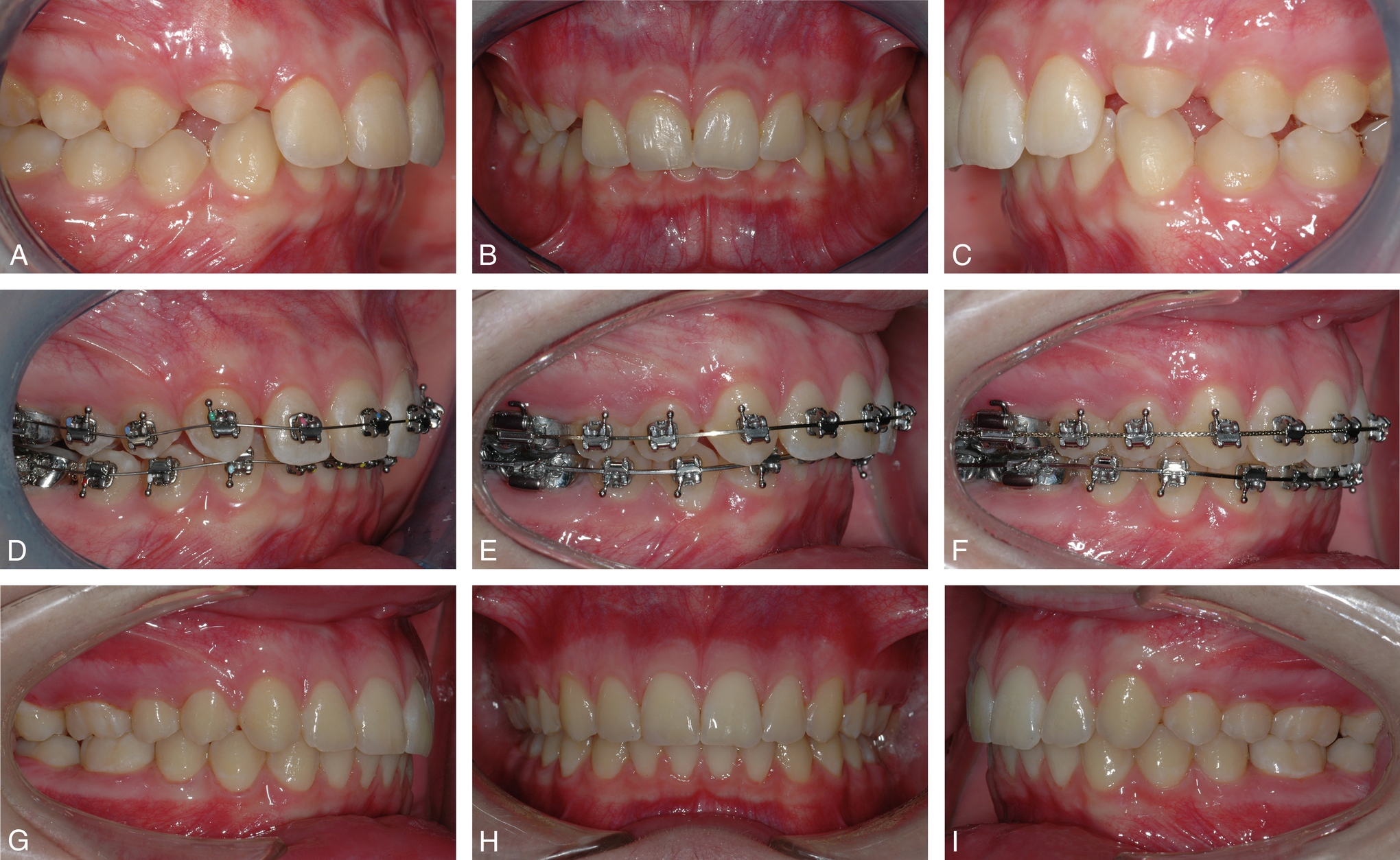
A 12.5-year-old boy presented with a Class I malocclusion. His maxillary canines ectopically positioned a few millimeters from the occlusal plane. With zero overbite and overjet, his anterior teeth were touching end-on. His arches were not coordinated. The main objectives for this case were to level and align upper and lower arch, add buccal crown torque to upper incisors, coordinate both arches, and achieve a proper overbite and overjet. An active self-ligating straight wire appliance with a combination of heat-activated wires as well as steel wires was used. Active treatment was for 12 months.


 -inch, 4-oz elastics to level the occlusal plane. Q–S, Upper and lower 0.019- × 0.025-inch braided stainless steel final wire to improve intercuspation. Patient continues with vertical triangular elastics. T–V, Intraoral photographs after treatment. W–Z, Extraoral photograph after treatment.
 Case study 19.2
A 12-year-old boy with pseudo Class II malocclusion due to mesial rotation of the upper molars and Class II canines in centric relation (CR), protruded upper incisors, and increased overjet. He had slight upper incisor crowding, minor centric occlusion (CO)/CR discrepancy, and no temporomandibular joint symptoms and signs. Treatment was postponed until full eruption of the permanent teeth. Initial alignment and leveling was performed with 0.014-, 0.020-, and 0.019-inch × .025-inch thermally-activated cinched back wires. Short Class II elastics were used in the working stage.


Case study 19.3
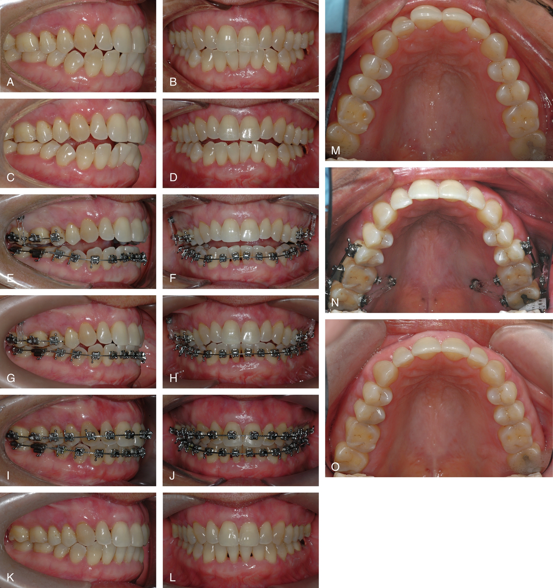
An 11.7-year-old girl presented with severe maxillary crowding, Class II canines, and upper right lateral incisor in crossbite. Upper and lower second premolars were removed as part of the treatment plan. After initial leveling and aligning, the mandibular occlusal plane was flattened using a 0.019- × 0.025-inch stainless steel wire. NiTi coils were used to closed extraction spaces in the mandible. Powerchain was used to close spaces in the maxilla. Short Class II elastics were used at the working stage and vertical triangular elastics were used at the finishing stage. An active self-ligating straight wire appliance was used. Active treatment was for 21 months.


 -inch, 4 oz. T–V, Upper and lower 0.019- × 0.025-inch stainless steel working wire with all spaces closed, arches coordinated and occlusal plane leveled. W–Y, Lower 0.019- × 0.025-inch braided finishing wire to improve intercuspation. Z–ZB, Intraoral photographs after treatment. ZC–ZF, Extraoral photographs after treatment.
Case study 19.4
A 10-year-old boy with a deep overbite, deviation of the maxillary dental midline to the right, lack of space for the maxillary right canine and slight mandibular incisor crowding. In centric relation (CR) he presented a full Class II. He had minor centric occlusion (CO)-CR discrepancy, no temporomandibular joint symptoms and signs. Extraction of 5.4 and 5.5 was performed and a Nance button installed. Almost at the end of the late mixed dentition, treatment with appliances was started and 1.5 and 2.5 were extracted.


Summary
The advantages of the SWA are unquestionable. Over 50 years after its introduction to our specialty, it remains the most popular orthodontic appliance used in the world. But today, at the beginning of the 21st century, the challenge is to integrate the SWA with recent changes in bracket design such as self-ligation and technologically advanced low-deflection thermal-activated archwires to provide orthodontists with a state-of-the-art appliance system that can deliver, through a practical, efficient, and reliable biomechanical system, excellent results for a wide range of dentofacial problems. The objective of this chapter is to delineate some of the basic principles of the SWA, emphasize the importance of optimal bracket placement, and provide readers with the framework of a simple, but complete, biomechanics tailored for active SLBs.