CHAPTER 45 Scaling and Root Planing
Periodontal instruments are designed for specific purposes such as removing calculus, planing root surfaces, curetting the gingiva, and removing diseased tissue. On first investigation, the variety of instruments available for similar purposes appears confusing. With experience, however, clinicians select a relatively small set that fulfills all requirements.
Classification of Periodontal Instruments
Periodontal instruments are classified according to the purposes they serve, as follows:
The wearing and cutting qualities of some types of steel used in periodontal instruments have been tested,80,81,142 but specifications vary among manufacturers.142 Stainless steel is used most often in instrument manufacture. High-carbon-content steel instruments are also available and are considered by some clinicians to be superior.
Each group of instruments has characteristic features; individual therapists often develop variations with which they operate most effectively. Small instruments are recommended to fit into periodontal pockets without injuring the soft tissues.105,107,108,159
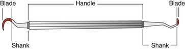
The parts of each instrument are referred to as the working end, shank, and handle (Figure 45-1).
Periodontal Probes
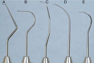
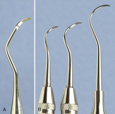
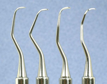
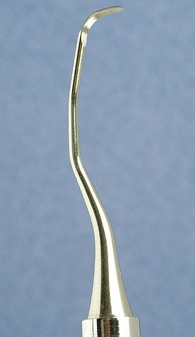
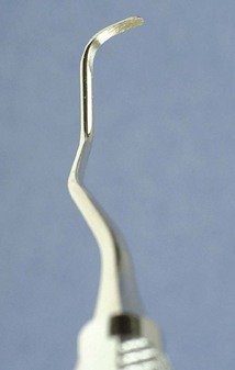
Periodontal probes are used to measure the depth of pockets and to determine their configuration. The typical probe is a tapered, rodlike instrument calibrated in millimeters, with a blunt, rounded tip (Figure 45-2). There are several other designs with various millimeter calibrations (Figure 45-3). The World Health Organization (WHO) probe has millimeter markings and a small, round ball at the tip (Figure 45-3, E). Ideally, these probes are thin, and the shank is angled to allow easy insertion into the pocket. Furcation areas can best be evaluated with the curved, blunt Nabers probe (Figure 45-4).
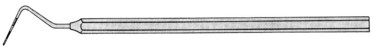
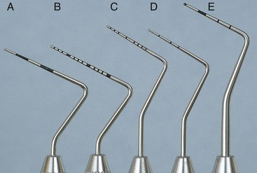
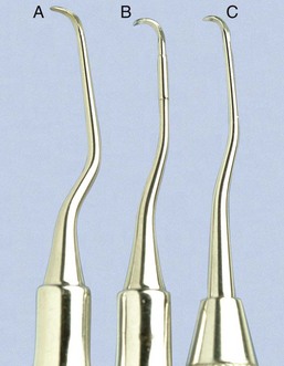
Figure 45-3 Types of periodontal probes. A, Marquis color-coded probe. Calibrations are in 3-mm sections. B, UNC-15 probe, a 15-mm long probe with millimeter markings at each millimeter and color coding at the fifth, tenth, and fifteenth millimeters. C, University of Michigan “O” probe, with Williams markings (at 1, 2, 3, 5, 7, 8, 9, and 10 mm). D, Michigan “O” probe with markings at 3, 6, and 8 mm. E, World Health Organization (WHO) probe, which has a 0.5-mm ball at the tip and millimeter markings at 3.5, 8.5, and 11.5 mm and color coding from 3.5 to 5.5 mm.
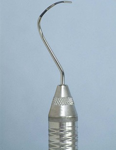
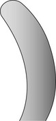
Figure 45-4 Curved #2 Nabers probe for detection of furcation areas, with color-coded markings at 3, 6, 9, and 12 mm.
When measuring a pocket, the probe is inserted with a firm, gentle pressure to the bottom of the pocket. The shank should be aligned with the long axis of the tooth surface to be probed. Several measurements are made to determine the level of attachment along the surface of the tooth.
Explorers
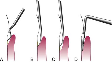
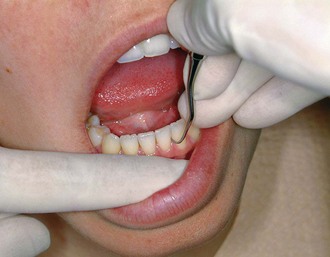
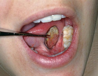
Explorers are used to locate subgingival deposits and carious areas and to check the smoothness of the root surfaces after root planing. Explorers are designed with different shapes and angles, with various uses (Figure 45-5), as well as limitations (Figure 45-6). The periodontal probe can also be useful in the detection of subgingival deposits (Figure 45-6, D).
Scaling and Curettage Instruments
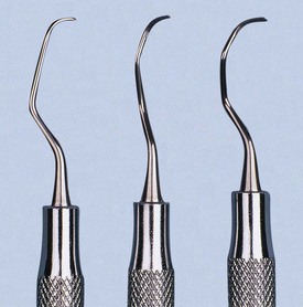
Scaling and curettage instruments are illustrated in Figure 45-7.
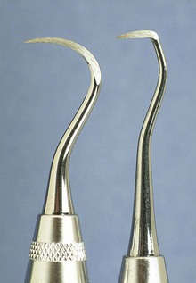
Sickle Scalers
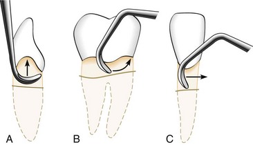
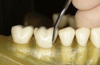
Sickle scalers have a flat surface and two cutting edges that converge in a sharply pointed tip. The shape of the instrument makes the tip strong so that it will not break off during use (Figure 45-8). The sickle scaler is used primarily to remove supragingival calculus (Figure 45-9). Because of the design of this instrument, it is difficult to insert a large sickle blade under the gingiva without damaging the surrounding gingival tissues (Figure 45-10). Small, curved sickle scaler blades such as the 204SD can be inserted under ledges of calculus several millimeters below the gingiva. Sickle scalers are used with a pull stroke.
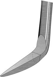
Figure 45-8 Basic characteristics of a sickle scaler: triangular shape, double-cutting edge, and pointed tip.
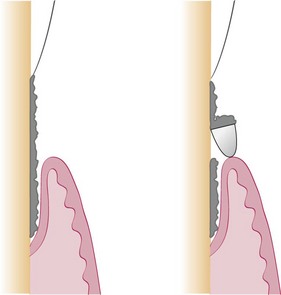
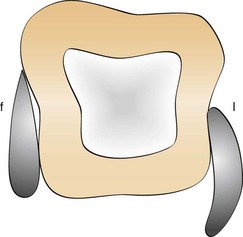
Figure 45-10 Subgingival adaptation around the root is better with the curette than with the sickle; f, facial; l, lingual.
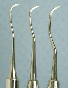
It is important to note that sickle scalers with the same basic design can be obtained with different blade sizes and shank types to adapt to specific uses. The U15/30 (Figure 45-11), Ball, and Indiana University sickle scalers are large. The Jaquette sickle scalers #1, 2, and 3 have medium-size blades. The curved 204 posterior sickle scalers are available with large, medium, or small blades (Figure 45-12). The Montana Jack sickle scaler and the Nevi 2, Nevi 3, and Nevi 4 curved posterior sickle scalers are all thin enough to be inserted several millimeters subgingivally for removal of light to moderate ledges of calculus. The selection of these instruments should be based on the area to be scaled. Sickle scalers with straight shanks are designed for use on anterior teeth and premolars. Sickle scalers with contra-angled shanks adapt to posterior teeth.
Curettes
The curette is the instrument of choice for removing deep subgingival calculus, root planing altered cementum, and removing the soft tissue lining the periodontal pocket (Figure 45-13). Each working end has a cutting edge on both sides of the blade and a rounded toe. The curette is finer than the sickle scalers and does not have any sharp points or corners other than the cutting edges of the blade (Figure 45-14). Therefore curettes can be adapted and provide good access to deep pockets, with minimal soft tissue trauma (see Figure 45-10). In cross-section the blade appears semicircular with a convex base. The lateral border of the convex base forms a cutting edge with the face of the semicircular blade. There are cutting edges on both sides of the blade. Both single- and double-end curettes may be obtained, depending on the preference of the operator.
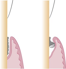
As shown in Figure 45-10, the curved blade and rounded toe of the curette allow the blade to adapt better to the root surface, unlike the straight design and pointed end of a sickle scaler, which can cause tissue laceration and trauma. There are two basic types of curettes: universal and area specific.
Universal Curettes
Universal curettes have cutting edges that may be inserted in most areas of the dentition by altering and adapting the finger rest, fulcrum, and hand position of the operator. The blade size and the angle and length of the shank may vary, but the face of the blade of every universal curette is at a 90-degree angle (perpendicular) to the lower shank when seen in cross-section from the tip (Figure 45-15, A). The blade of the universal curette is curved in one direction from the head of the blade to the toe. The Barnhart curettes #1-2 and 5-6 and the Columbia curettes #13-14, 2R-2L, and 4R-4L (Figures 45-16 and 45-17, A) are examples of universal curettes. Other popular universal curettes are the Younger-Good #7-8, the McCall’s #17-18, and the Indiana University #17-18 (Figure 45-17, B).
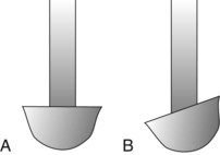
Figure 45-15 Principal types of curettes as seen from the toe of the instrument. A, Universal curette. B, Gracey curette. Note the offset blade angulation of the Gracey curette.
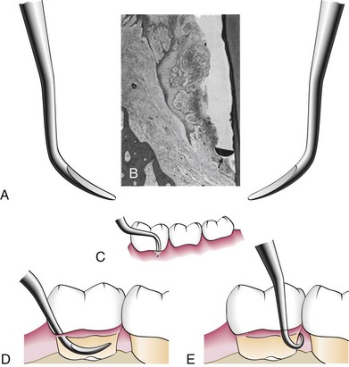
Figure 45-16 A, Double-ended curette for the removal of subgingival calculus. B, Cross-section of the curette blade (arrow) against the cemental wall of a deep periodontal pocket. C, Curette in position at the base of a periodontal pocket on the facial surface of a mandibular molar. D, Curette inserted in a pocket with the tip directed apically. E, Curette in position at the base of a pocket on the distal surface of the mandibular molar.
Area-Specific Curettes
Gracey Curettes
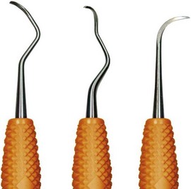
Gracey curettes are representative of the area-specific curettes, a set of several instruments designed and angled to adapt to specific anatomic areas of the dentition (Figure 45-18). These curettes and their modifications are probably the best instruments for subgingival scaling and root planing because they provide the best adaptation to complex root anatomy.
Double-ended Gracey curettes are paired in the following manner:
Single-ended Gracey curettes can also be obtained; a set of these curettes comprises 14 instruments. Although these curettes are designed to be used in specific areas, an experienced operator can adapt each instrument for use in several different areas by altering the position of his or her hand and the position of the patient.
The Gracey curettes also differ from the universal curettes in that the blade is not at a 90-degree angle to the lower shank. The term offset blade is used to describe Gracey curettes because they are angled approximately 60 to 70 degrees from the lower shank (see Figure 45-15, B). This unique angulation allows the blade to be inserted in the precise position necessary for subgingival scaling and root planing, provided that the lower shank is parallel with the long axis of the tooth surface being scaled.
Area-specific curettes also have a curved blade. Whereas the blade of the universal curette is curved in one direction (Figure 45-21, A), the Gracey blade is curved from head to toe and also along the side of the cutting edge (Figure 45-21, B). Thus only a pull stroke can be used. Table 45-1 lists some of the major differences between Gracey (area-specific) curettes and universal curettes.
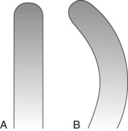
Figure 45-21 A, Universal curette as seen from the blade. Note that the blade is straight. B, Gracey curette as seen from the blade. The blade is curved; only the convex cutting edge is used.
TABLE 45-1 Comparison of Area-Specific (Gracey) and Universal Curettes
| Gracey Curette | Universal Curette | |
|---|---|---|
| Area of use | Set of many curettes designed for specific areas and surfaces. | One curette designed for all areas and surfaces. |
| Cutting Edge | ||
| Use | One cutting edge used; work with outer edge only. | Both cutting edges used; work with either outer or inner edge. |
| Curvature | Curved in two planes; blade curves up and to the side. | Curved in one plane; blade curves up, not to the side. |
| Blade angle | Offset blade; face of blade beveled at 60 degrees to shank. | Blade not offset; face of blade beveled at 90 degrees to shank. |
Modified from Pattison G, Pattison A: Periodontal instrumentation, ed 2, Norwalk, CT, 1992, Appleton & Lange.
Gracey curettes are available with either a “rigid” or a “finishing” type of shank. The rigid Gracey has a larger, stronger, and less flexible shank and blade than the standard finishing Gracey. The rigid shank allows the removal of moderate to heavy calculus without using a separate set of heavy scalers, such as sickles and hoes. Although some clinicians prefer the enhanced tactile sensitivity that the flexible shank of the finishing Gracey provides, both types of Gracey curettes are suitable for root planing.
Recent additions to the Gracey curette set have been the Gracey #15-16 and 17-18. The Gracey #15-16 is a modification of the standard #11-12 and is designed for the mesial surfaces of posterior teeth (Figure 45-22). It consists of a Gracey #11-12 blade combined with the more acutely angled #13-14 shank. When the clinician is using an intraoral finger rest, it is often difficult to position the lower shank of the Gracey #11-12 so that it is parallel with the mesial surfaces of the posterior teeth, especially on the mandibular molars. The new shank angulation of the Gracey #15-16 allows better adaptation to posterior mesial surfaces from a front position with intraoral rests. If alternative fulcrums, such as extraoral or opposite-arch rests, are used, the Gracey #11-12 works well and the new #15-16 is not essential. The Gracey #17-18 is a modification of the #13-14. It has a terminal shank elongated by 3 mm and a more accentuated angulation of the shank to provide complete occlusal clearance and better access to all posterior distal surfaces. The horizontal handle position minimizes interference from opposing arches and allows a more relaxed hand position when scaling distal surfaces. In addition, the blade is 1 mm shorter to allow better adaptation of the blade to distal tooth surfaces.
Extended-Shank Curettes
Extended-shank curettes, such as the After Five curettes (Hu-Friedy, Chicago), are modifications of the standard Gracey curette design. The terminal shank is 3 mm longer, allowing extension into deeper periodontal pockets of 5 mm or more (Figures 45-23 and 45-24). Other features of the After Five curette include a thinned blade for smoother subgingival insertion and reduced tissue distention and a large-diameter, tapered shank. All standard Gracey numbers except for the #9-10 (i.e., #1-2, 3-4, 5-6, 7-8, 11-12, or 13-14) are available in the After Five series. The After Five curettes are available in finishing or rigid designs. For heavy or tenacious calculus removal, rigid After Five curettes should be used. For light scaling or deplaquing in a periodontal maintenance patient, the thinner, finishing After Five curettes will insert subgingivally more easily.
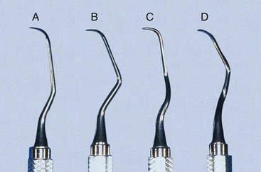
Figure 45-23 After Five curette. Note the extra 3 mm in the terminal shank of the After Five curette compared with the standard Gracey curette. A, #5-6; B, #7-8; C, #11-12; D, #13-14.
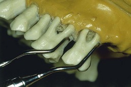
Figure 45-24 Comparison of After Five curette with standard Gracey curette. Rigid Gracey #13-14 adapted to the distal surface of the first molar and rigid After Five #13-14 adapted to the distal surface of the second molar. Notice the extralong shank of the After Five curette, which allows deeper insertion and better access.
Mini-Bladed Curettes
Mini-bladed curettes, such as the Hu-Friedy Mini Five curettes, are modifications of the After Five curettes. The Mini Five curettes feature blades that are half the length of the After Five or standard Gracey curettes (Figure 45-25). The shorter blade allows easier insertion and adaptation in deep, narrow pockets; furcations; developmental grooves; line angles; and deep, tight, facial, lingual, or palatal pockets. In any area in which root morphology or tight tissue prevents full insertion of the standard Gracey or After Five blade, the Mini Five curettes can be used with vertical strokes, with reduced tissue distention, and without tissue trauma (Figure 45-26).
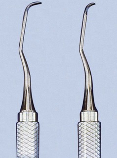
Figure 45-25 Comparison of After Five curette and Mini Five curette. The shorter Mini Five blade (half the length) allows increased access and reduced tissue trauma.
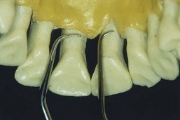
Figure 45-26 Comparison of standard rigid Gracey #5-6 with rigid Mini Five #5-6 on the palatal surfaces of the maxillary central incisors. Mini Five curette can be inserted to the base of these tight anterior pockets and used with a straight vertical stroke. Standard Gracey or After Five curette usually cannot be inserted vertically in this area because the blade is too long.
In the past the only solution in most of these areas of difficult access was to use the Gracey curettes with a toe-down horizontal stroke. The Mini Five curettes, along with other short-bladed instruments relatively recently introduced, open a new chapter in the history of root instrumentation by allowing access to areas that previously were extremely difficult or impossible to reach with standard instruments. The Mini Five curettes are available in both finishing and rigid designs. Rigid Mini Five curettes are recommended for calculus removal. The more flexible, shanked, finishing Mini Five curettes are appropriate for light scaling and deplaquing in periodontal maintenance patients with tight pockets. As with the After Five series, the Mini Five curettes are available in all standard Gracey numbers, except the #9-10.
The recently introduced Micro Mini Five Gracey curettes (Hu-Friedy, Chicago) have blades that are 20% thinner and smaller than the Mini Five curettes (Figures 45-27 and 45-28) These are the smallest of all curettes, and they provide exceptional access and adaptation to tight, deep, or narrow pockets; narrow furcations; developmental depressions; line angles; and deep pockets on facial, lingual, or palatal surfaces. In areas in which root morphology or tight, thin tissue prevents easy insertion of other mini-bladed curettes, the Micro Mini Five curettes can be used with vertical strokes without causing tissue distension or tissue trauma.
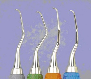
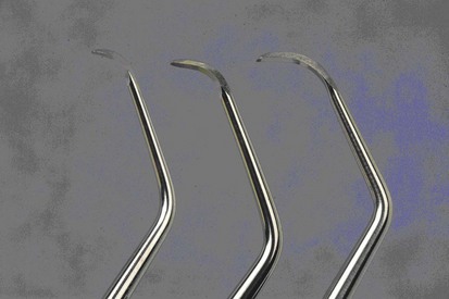
Figure 45-28 Comparison of Gracey curette blades. Left to right, Micro Mini Five #7-8, Mini Five #7-8, Standard #7-8.
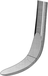
The Gracey curvettes are another set of four mini-bladed curettes; the Sub-0 and the #1-2 are used for anterior teeth and premolars, the #11-12 is used for posterior mesial surfaces, and the #13-14 for posterior distal surfaces. The blade length of these instruments is 50% shorter than that of the conventional Gracey curette, and the blade has been curved slightly upward (Figure 45-29). This curvature allows the Gracey curvettes to adapt more closely to the tooth surface than any other curettes, especially on the anterior teeth and on line angles (Figure 45-30). However, this curvature also carries the risk of gouging or “grooving” into the root surfaces on the proximal surfaces of the posterior teeth when the Gracey curvette #11-12 or 13-14 is used. Additional features that represent improvements on the standard Gracey curettes are a precision-balanced blade tip in direct alignment with the handle, a blade tip perpendicular to the handle, and a shank closer to parallel with the handle.
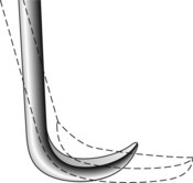
Figure 45-29 Gracey Curvette blade. This diagram shows the 50% shorter blade of the Gracey Curvette superimposed on the standard Gracey curette blade (dotted lines). Notice the upward curvature of the Curvette blade and blade tip.
(Redrawn from Pattison G, Pattison A: Periodontal instrumentation, ed 2, Norwalk, Conn, 1992, Appleton & Lange.)
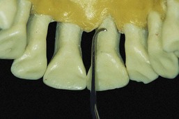
Figure 45-30 Gracey Curvette Sub-0 on the palatal surface of a maxillary central incisor. The long shank and short, curved, and blunted tip make this a superior instrument for deep anterior pockets. This curette provides excellent blade adaptation to the narrow root curvatures of the maxillary and mandibular anterior teeth.
For many years, the Morse scaler, a miniature sickle, was the only mini-bladed instrument available. However, the mini-bladed curettes have largely replaced this instrument (Figure 45-31).
Langer and Mini-Langer Curettes
The Langer and Mini Langer curettes are a set of three curettes combining the shank design of the standard Gracey #5-6, 11-12, and 13-14 curettes with a universal blade honed at 90 degrees rather than the offset blade of the Gracey curette. This marriage of the Gracey and universal curette designs allows the advantages of the area-specific shank to be combined with the versatility of the universal curette blade. The Langer #5-6 curette adapts to the mesial and distal surfaces of anterior teeth; the Langer #1-2 curette (Gracey #11-12 shank) adapts to the mesial and distal surfaces of mandibular posterior teeth; and the Langer #3-4 curette (Gracey #13-14 shank) adapts to the mesial and distal surfaces of maxillary posterior teeth (Figure 45-32). These instruments can be adapted to both mesial and distal tooth surfaces without changing instruments. The standard Langer curette shanks are heavier than a finishing Gracey but less rigid than the rigid Gracey. Langer curettes are also available with either rigid or finishing shanks and can be obtained in the extended-shank (After Five) and mini-bladed (Mini Five) versions.
Schwartz Periotrievers
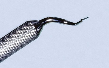
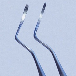
The Schwartz Periotrievers are a set of two double-ended, highly magnetized instruments designed for the retrieval of broken instrument tips from the periodontal pocket (Figures 45-33 and 45-34). They are indispensable when the clinician has broken a curette tip in a furcation or deep pocket.134
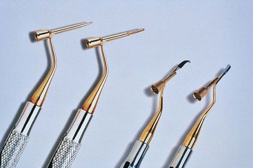
Plastic and Titanium Instruments for Implants
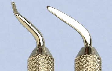
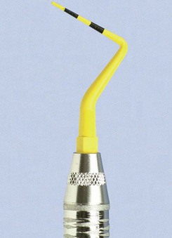
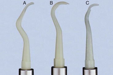
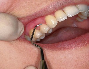
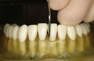
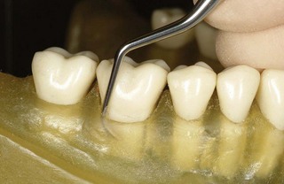
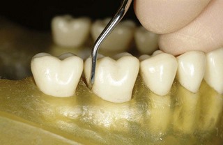
Several different companies are manufacturing plastic and titanium instruments for use on titanium and other implant abutment materials. It is important that plastic or titanium instruments be used to avoid scarring and permanent damage to the implants* (Figures 45-35, 45-36, and 45-37).
Hoe Scalers
Hoe scalers are used for scaling of ledges or rings of calculus (Figure 45-38). The blade is bent at a 99-degree angle; the cutting edge is formed by the junction of the flattened terminal surface with the inner aspect of the blade. The cutting edge is beveled at 45 degrees. The blade is slightly bowed so that it can maintain contact at two points on a convex surface. The back of the blade is rounded, and the blade has been reduced to minimal thickness to permit access to the roots without interference from the adjacent tissues.
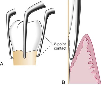
Figure 45-38 A, Hoe scalers designed for different tooth surfaces, showing “two-point” contact. B, Hoe scaler in a periodontal pocket. The back of the blade is rounded for easier access. The instrument contacts the tooth at two points for stability.
Hoe scalers are used in the following manner:
McCall’s #3, 4, 5, 6, 7, and 8 are a set of six hoe scalers designed to provide access to all tooth surfaces. Each instrument has a different angle between the shank and handle.
Files
Files have a series of blades on a base (Figure 45-39). Their primary function is to fracture or crush large deposits of tenacious calculus or burnished sheets of calculus. Files can easily gouge and roughen root surfaces when used improperly. Therefore they are not suitable for fine scaling and root planing. Mini-bladed curettes are currently preferred for fine scaling in areas where files were once used. Files are sometimes used for removing overhanging margins of dental restorations.
Chisel Scalers
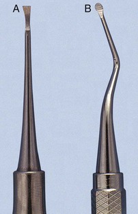
The chisel scaler, designed for the proximal surfaces of teeth too closely spaced to permit the use of other scalers, is usually used in the anterior part of the mouth. It is a double-ended instrument with a curved shank at one end and a straight shank at the other (see Figure 45-39); the blades are slightly curved and have a straight cutting edge beveled at 45 degrees.
The chisel is inserted from the facial surface. The slight curve of the blade makes it possible to stabilize it against the proximal surface, whereas the cutting edge engages the calculus without nicking the tooth. The instrument is activated with a push motion while the side of the blade is held firmly against the root.
Quétin Furcation Curettes
The Quétin furcation curettes are actually hoes with a shallow, half-moon radius that fits into the roof or floor of the furcation. The curvature of the tip also fits into developmental depressions on the inner aspects of the roots. The shanks are slightly curved for better access, and the tips are available in two widths (Figure 45-40). The BL1 (buccal-lingual) and MD1 (mesial-distal) instruments are small and fine, with a 0.9-mm blade width. The BL2 and MD2 instruments are larger and wider, with a 1.3-mm blade width.
These instruments remove burnished calculus from recessed areas of the furcation where curettes, even the mini-bladed curettes, are often too large to gain access. Using mini-bladed Gracey curettes and Gracey Curvettes in the roof or floor of the furcation may unintentionally create gouges and grooves. The Quétin instruments, however, are well suited for this area and lessen the likelihood of root damage.
Diamond-Coated Files
Diamond-coated files are unique instruments used for final finishing of root surfaces. These files do not have cutting edges; instead, they are coated with very-fine-grit diamond (Figure 45-41). The most useful diamond files are the buccal-lingual instruments, which are used in furcations and also adapt well to many other root surfaces.
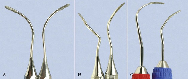
Figure 45-41 Diamond files. A, #1,2 (Brasseler, Savannah, GA); B, #3,4 (Brasseler). C, SDCN 7, SDCM/D 7 (Hu-Friedy, Chicago).
New diamond files are sharply abrasive and should be used with light, even pressure against the root surface to avoid gouging or grooving. When viewing the root surface with the dental endoscope after all tactilely detectable deposits are gone, small embedded remnants of calculus in the root surface can be observed. Diamond files are used similar to an emery board to remove these minute remnants of calculus from the root, creating a surface that is free of all visible accretions. Diamond files can produce a smooth, even, clean, and highly polished root surface.
Diamond files must be used carefully because they can cause overinstrumentation of the root surface. They will remove too much root structure if they are used with excessive force, are poorly adapted to root morphology, or used too long in one place.
Diamond files are particularly effective when used with the dental endoscope, which reveals residual deposits and directs the clinician to the exact area for instrumentation.
Ultrasonic and Sonic Instruments
Ultrasonic instruments may be used for removing plaque, scaling, curetting, and removing stain (see Chapter 46).
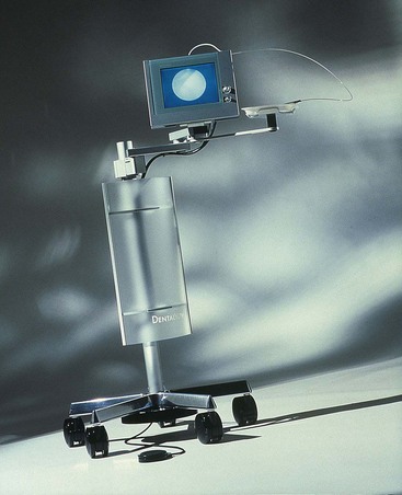
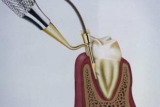
Dental Endoscope
A dental endoscope has been introduced for use subgingivally in the diagnosis and treatment of periodontal disease (Figure 45-42). The Perioscopy system (Perioscopy, Inc, Oakland, CA) consists of a 0.99-mm-diameter, reusable fiberoptic endoscope over which is fitted a disposable, sterile sheath. The fiberoptic endoscope fits onto periodontal probes and ultrasonic instruments that have been designed to accept it (Figure 45-43). The sheath delivers water irrigation that flushes the pocket while the endoscope is being used, keeping the field clear. The fiberoptic endoscope attaches to a medical-grade charged-coupled device (CCD) video camera and light source that produces an image on a flat-panel monitor for viewing during subgingival exploration and instrumentation. This device allows clear visualization deeply into subgingival pockets and furcations (Figure 45-44). It permits operators to detect the presence and location of subgingival deposits and guides them in the thorough removal of these deposits. Magnification ranges from 24X to 48X, enabling visualization of even minute deposits of plaque and calculus. Using this device, operators can achieve levels of root debridement and cleanliness that are much more difficult or impossible to produce without it.145,146,163,164 The Perioscopy system can also be used to evaluate subgingival areas for caries, defective restorations, root fractures, and resorption.
Cleansing and Polishing Instruments
Rubber Cups
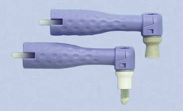
Rubber cups consist of a rubber shell with or without webbed configurations in the hollow interior (Figure 45-45). They are used in the handpiece with a special prophylaxis angle. The handpiece, prophylaxis angle, and rubber cup must be sterilized after each patient use, or a disposable plastic prophylaxis angle and rubber cup may be used and then discarded (Figure 45-46). A good cleansing and polishing paste that contains fluoride should be used and kept moist to minimize frictional heat as the cup revolves. Polishing pastes are available in fine, medium, or coarse grits and are packaged in small, convenient, single-use containers. Aggressive use of the rubber cup with any abrasive may remove the layer of cementum, which is thin in the cervical area.
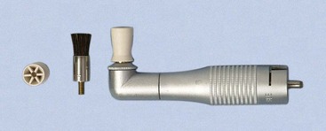
Bristle Brushes
Bristle brushes are available in wheel and cup shapes (see Figure 45-45). The brush is used in the prophylaxis angle with a polishing paste. Because the bristles are stiff, use of the brush should be confined to the crown to avoid injuring the cementum and the gingiva.
Dental Tape
Dental tape with polishing paste is used for polishing proximal surfaces that are inaccessible to other polishing instruments. The tape is passed interproximally while being kept at a right angle to the long axis of the tooth and is activated with a firm labiolingual motion. Particular care is taken to avoid injury to the gingiva. The area should be cleansed with warm water to remove all remnants of paste.
Air-Powder Polishing
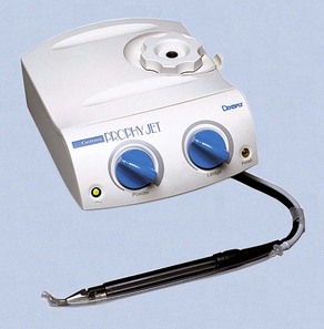
The first specially designed handpiece to deliver an air-powered slurry of warm water and sodium bicarbonate for polishing was introduced in the early 1980s. This device, called the Prophy-Jet (Dentsply International, York, PA) is very effective for the removal of extrinsic stains and soft deposits (Figure 45-47). The slurry removes stains rapidly and efficiently by mechanical abrasion and provides warm water for rinsing and lavage. The flow rate of abrasive cleansing power can be adjusted to increase the amount of powder for heavier stain removal. Currently, many manufacturers produce air-powder polishing systems that use various powder formulas.
The results of studies on the abrasive effect of the air-powder polishing devices using sodium bicarbonate and aluminum trihydroxide on cementum and dentin show that significant tooth substance can be lost.2,19,106,114 Damage to gingival tissue is transient and insignificant clinically, but amalgam restorations, composite resins, cements, and other nonmetallic materials can be roughened.13,41,64,86,157 Polishing powders containing glycine rather than sodium bicarbonate recently have been introduced for subgingival biofilm removal from root surfaces.93a,113 Air-powder polishing can be used safely on titanium implant surfaces.71,88,122
Patients with medical histories of respiratory illnesses and hemodialysis are not candidates for the use of the air-powder polishing device.141,161 Powders containing sodium bicarbonate should not be used on patients with histories of hypertension, sodium-restricted diets, or medications affecting the electrolyte balance.121 Patients with infectious diseases should not be treated with this device because of the large quantity of aerosol created. A preprocedural rinse with 0.12% chlorhexidine gluconate should be used to minimize the microbial content of the aerosol.17 High-speed evacuation should also be used to eliminate as much of the aerosol as possible.54a
 Science Transfer
Scaling and root planing is the foundation of periodontal treatment. The thorough removal of subgingival plaque and calculus is essential for successful periodontal therapy. Because the removal of subgingival calculus embedded in the root is such a demanding clinical skill, it takes years of experience and a desire for perfection for clinicians to become highly competent. In many cases, such as furcations, it is impossible to root plane all surfaces and remove all calculus during phase I therapy and frequently there will be residual calculus visually present when the root surfaces are exposed during flap surgery. Therefore root planing should also be an important part of all flap surgeries, and in some difficult cases, it will be necessary to use mechanical instruments, such as ultrasonic scalers and rotary instruments, to achieve total removal of all embedded calculus.
Clinicians should educate patients so that they appreciate the time and high level of skill necessary for successful root planing. In most cases, local infiltration anesthesia is needed so that patients are comfortable and the clinician can focus on obtaining a smooth glass-like root surface free of calculus. The presence of residual calculus after treatment will compromise the ability to obtain healthy gingiva and pocket depth reduction. The persistence of bleeding on probing after treatment can be the result of root roughness associated with incompletely removed subgingival calculus and persistence of unhealthy bacterial biofilms on the root surface.
General Principles of Instrumentation
Effective instrumentation is governed by a number of general principles that are common to all periodontal instruments. Proper position of the patient and the operator, illumination and retraction for optimal visibility, and sharp instruments are fundamental prerequisites. A constant awareness of tooth and root morphologic features and of the condition of the periodontal tissues is also essential. Knowledge of instrument design enables the clinician to select the proper instrument for the procedure and the correct area in which it will be performed. In addition to these principles, the basic concepts of grasp, finger rest, adaptation, angulation, and stroke must be understood before clinical instrument-handling skills can be mastered.
Accessibility: Positioning of Patient and Operator
Accessibility facilitates thoroughness of instrumentation. The position of the patient and operator should provide maximal accessibility to the area of operation. Inadequate accessibility impedes thorough instrumentation, prematurely tires the operator, and diminishes his or her effectiveness.
The clinician should be seated on a comfortable operating stool that has been positioned so that the clinician’s feet are flat on the floor with the thighs parallel to the floor. The clinician should be able to observe the field of operation while keeping the back straight and the head erect.
The patient should be in a supine position and placed so that the mouth is close to the resting elbow of the clinician. For instrumentation of the maxillary arch, the patient should be asked to raise the chin slightly to provide optimal visibility and accessibility. For instrumentation on the mandibular arch, it may be necessary to raise the back of the chair slightly and request that the patient lower the chin until the mandible is parallel to the floor. This will especially facilitate work on the lingual surfaces of the mandibular anterior teeth.
Visibility, Illumination, and Retraction
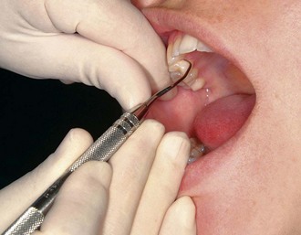
Whenever possible, direct vision with direct illumination from the dental light is most desirable (Figure 45-48). If this is not possible, indirect vision may be obtained by using the mouth mirror (Figure 45-49) and indirect illumination may be obtained by using the mirror to reflect light to where it is needed (Figure 45-50). Indirect vision and indirect illumination are often used simultaneously (Figure 45-51).
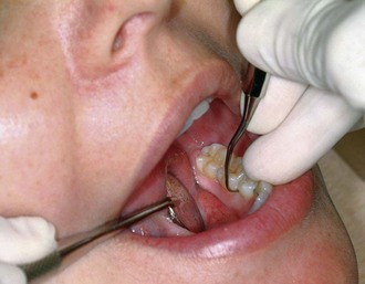
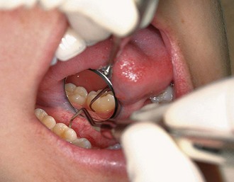
Figure 45-49 Indirect vision using the mirror for the lingual surfaces of the mandibular anterior teeth.
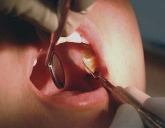
Figure 45-50 Indirect illumination using the mirror to reflect light onto the maxillary left posterior lingual region.
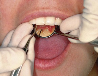
Figure 45-51 Combination of indirect illumination and indirect vision for the lingual surfaces of the maxillary anterior teeth.
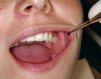
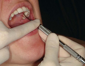
Retraction provides visibility, accessibility, and illumination. Depending on the location of the area of operation, the fingers and/or the mirror are used for retraction. The mirror may be used for retraction of the cheeks or the tongue; the index finger is used for retraction of the lips or cheeks. The following methods are effective for retraction:
When retracting, care should be taken to avoid irritation to the angles of the mouth. If the lips and skin are dry, softening the lips with petroleum jelly before instrumentation is a helpful precaution against cracking and bleeding. Careful retraction is especially important for patients with a history of recurrent herpes labialis because these patients may easily develop herpetic lesions after instrumentation.
Condition and Sharpness of Instruments
Before any instrumentation, all instruments should be inspected to make sure that they are clean, sterile, and in good condition. The working ends of pointed or bladed instruments must be sharp to be effective. Sharp instruments enhance tactile sensitivity and allow the clinician to work more precisely and efficiently (see later discussion). Dull instruments may lead to incomplete calculus removal and unnecessary trauma because of the excess force usually applied to compensate for their ineffectiveness.
Maintaining a Clean Field
Despite good visibility, illumination, and retraction, instrumentation can be hampered if the operative field is obscured by saliva, blood, and debris. The pooling of saliva interferes with visibility during instrumentation and impedes control because a firm finger rest cannot be established on wet, slippery tooth surfaces. Adequate suction is essential and can be achieved with a saliva ejector or, if working with an assistant, an aspirator.
Gingival bleeding is an unavoidable consequence of subgingival instrumentation. In areas of inflammation, bleeding is not necessarily an indication of trauma from incorrect technique but rather may indicate ulceration of the pocket epithelium. Blood and debris can be removed from the operative field with suction and by wiping or blotting with gauze squares. The operative field should also be flushed occasionally with water.
Compressed air and gauze squares can be used to facilitate visual inspection of tooth surfaces just below the gingival margin during instrumentation. A jet of air directed into the pocket deflects a retractable gingival margin. Retractable tissue can also be deflected away from the tooth by gently packing the edge of a gauze square into the pocket with the back of a curette. Immediately after the gauze is removed, the subgingival area should be clean, dry, and clearly visible for a brief interval.
Instrument Stabilization
Stability of the instrument and the hand is the primary requisite for controlled instrumentation. Stability and control are essential for effective instrumentation and avoidance of injury to the patient or clinician. The two factors of major importance in providing stability are the instrument grasp and the finger rest.
Instrument Grasp
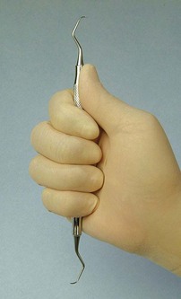
A proper grasp is essential for precise control of movements made during periodontal instrumentation. The most effective and stable grasp for all periodontal instruments is the modified pen grasp (Figure 45-55). Although other grasps are possible, this modification of the standard pen grasp (Figure 45-56) ensures the greatest control in performing intraoral procedures.
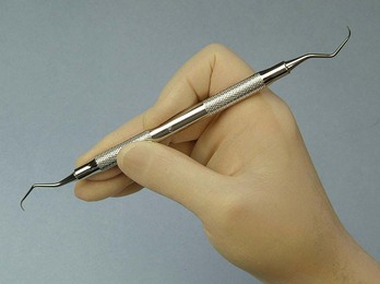
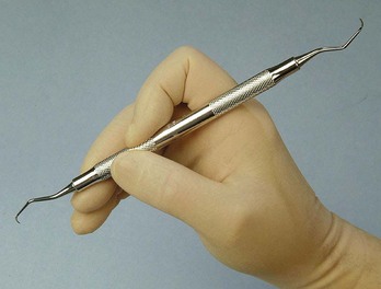
The thumb, index finger, and middle finger are used to hold the instrument as a pen is held, but the middle finger is positioned so that the side of the pad next to the fingernail is resting on the instrument shank. The index finger is bent at the second joint from the fingertip and is positioned well above the middle finger on the same side of the handle.
The pad of the thumb is placed midway between the middle and index fingers on the opposite side of the handle. This creates a triangle of forces, or tripod effect, that enhances control because it counteracts the tendency of the instrument to turn uncontrollably between the fingers when scaling force is applied to the tooth. This stable modified pen grasp enhances control because it enables the clinician to roll the instrument in precise degrees with the thumb against the index and middle fingers to adapt the blade to the slightest changes in tooth contour. The modified pen grasp also enhances tactile sensitivity because slight irregularities on the tooth surface are best perceived when the tactile-sensitive pad of the middle finger is placed on the shank of the instrument.
The palm and thumb grasp (Figure 45-57) is useful for stabilizing instruments during sharpening and for manipulating air and water syringes, but it is not recommended for periodontal instrumentation. Maneuverability and tactile sensitivity are so inhibited by this grasp that it is unsuitable for the precise, controlled movements necessary during periodontal procedures.
Finger Rest
The finger rest serves to stabilize the hand and the instrument by providing a firm fulcrum as movements are made to activate the instrument. A good finger rest prevents injury and laceration of the gingiva and surrounding tissues by poorly controlled instruments. The fourth (ring) finger is preferred by most clinicians for the finger rest. Although it is possible to use the third (middle) finger for the finger rest, this is not recommended because it restricts the arc of movement during the activation of strokes and severely curtails the use of the middle finger for both control and tactile sensitivity. Maximal control is achieved when the middle finger is kept between the instrument shank and the fourth finger. This “builtup” fulcrum is an integral part of the wrist-forearm action that activates the powerful working stroke for calculus removal. Whenever possible, these two fingers should be kept together to work as a one-unit fulcrum during scaling and root planing. Separation of the middle and fourth fingers during scaling strokes results in a loss of power and control because it forces the clinician to rely solely on finger flexing for activation of the instrument.
Finger rests may be generally classified as intraoral finger rests or extraoral fulcrums. Intraoral finger rests on tooth surfaces ideally are established close to the working area. Variations of intraoral finger rests and extraoral fulcrums are used whenever good angulation and a sufficient arc of movement cannot be achieved by a finger rest close to the working area. The following examples illustrate the different variations of the intraoral finger rest:
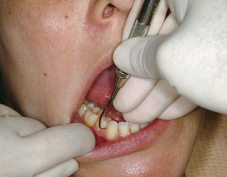
Figure 45-58 Intraoral conventional finger rest. The fourth finger rests on the occlusal surfaces of adjacent teeth.
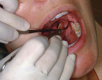
Figure 45-59 Intraoral cross-arch finger rest. The fourth finger rests on the incisal surfaces of teeth on the opposite side of the same arch.
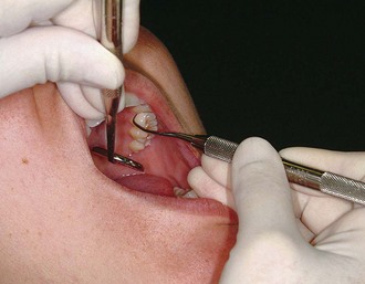
Figure 45-60 Intraoral opposite-arch finger rest. The fourth finger rests on the mandibular teeth while the maxillary posterior teeth are instrumented.
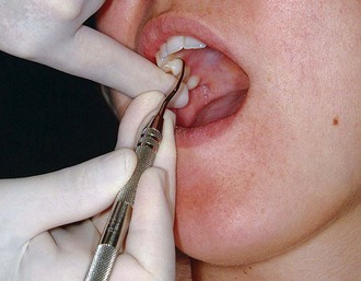
Figure 45-61 Intraoral finger-on-finger rest. The fourth finger rests on the index finger of the nonoperating hand.
Extraoral fulcrums are essential for effective instrumentation of some aspects of the maxillary posterior teeth. When properly established, they allow optimal access and angulation while providing adequate stabilization. Extraoral fulcrums are not “finger rests” in the literal sense because the tips or pads of the fingers are not used for extraoral fulcrums as they are for intraoral finger rests. Instead, as much of the front or back surface of the fingers as possible is placed on the patient’s face to provide the greatest degree of stability. The two most common extraoral fulcrums are used as follows:
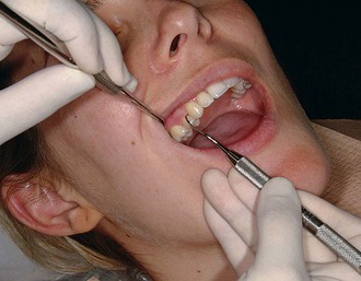
Figure 45-62 Extraoral palm-up fulcrum. The backs of the fingers rest on the right lateral aspect of the mandible while the maxillary right posterior teeth are instrumented.
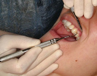
Figure 45-63 Extraoral palm-down fulcrum. The front surfaces of the fingers rest on the left lateral aspect of the mandible while the maxillary left posterior teeth are instrumented.
Both intraoral finger rests and extraoral fulcrums may be reinforced by applying the index finger or thumb of the nonoperating hand to the handle or shank of the instrument for added control and pressure against the tooth. The reinforcing finger is usually employed for opposite-arch or extraoral fulcrums when precise control and pressure are compromised by the longer distance between the fulcrum and the working end of the instrument. Figure 45-64 shows the index finger–reinforced rest, and Figure 45-65 shows the thumb-reinforced rest.
Instrument Activation
Adaptation
Adaptation refers to the manner in which the working end of a periodontal instrument is placed against the surface of a tooth. The objective of adaptation is to make the working end of the instrument conform to the contour of the tooth surface. Precise adaptation must be maintained with all instruments to avoid trauma to the soft tissues and root surfaces and to ensure maximum effectiveness of instrumentation.
Correct adaptation of the probe is quite simple. The tip and side of the probe should be flush against the tooth surface as vertical strokes are activated within the crevice. Bladed instruments (e.g., curettes) and sharp-pointed instruments (e.g., explorers) are more difficult to adapt. The ends of these instruments are sharp and can lacerate tissue, so adaptation in subgingival areas becomes especially important. The lower third of the working end, which is the last few millimeters adjacent to the toe or tip, must be kept in constant contact with the tooth while it is moving over varying tooth contours (Figure 45-66). Precise adaptation is maintained by carefully rolling the handle of the instrument against the index and middle fingers with the thumb. This rotates the instrument in slight degrees so that the toe or tip leads into concavities and around convexities. On convex surfaces such as line angles, it is not possible to adapt more than 1 or 2 mm of the working end against the tooth. Even on what appear to be broader, flatter surfaces, no more than 1 or 2 mm of the working end can be adapted because the tooth surface, although it may seem flat, is actually slightly curved.
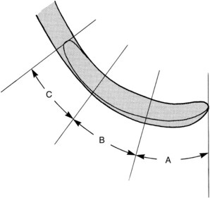
Figure 45-66 Gracey curette blade divided into three segments: A, the lower one-third of the blade, consisting of the terminal few millimeters adjacent to the toe; B, the middle one-third; and C, the upper one-third, which is adjacent to the shank.
If only the middle third of the working end is adapted on a convex surface so that the blade contacts the tooth at a tangent, the toe or sharp tip will jut out into soft tissue, causing trauma and discomfort (Figure 45-67).
Figure 45-67 Blade adaptation. The curette on the left is properly adapted to the root surface. The curette on the right is incorrectly adapted; the toe juts out, lacerating the soft tissues.
If the instrument is adapted so that only the toe or tip is in contact, the soft tissue can be distended or compressed by the back of the working end, also causing trauma and discomfort. A curette that is improperly adapted in this manner can be particularly damaging because the toe can gouge or groove the root surface.
Angulation
Angulation refers to the angle between the face of a bladed instrument and the tooth surface. It may also be called the tooth-blade relationship.
Correct angulation is essential for effective calculus removal. For subgingival insertion of a bladed instrument such as a curette, angulation should be as close to 0 degree as possible (Figure 45-68, A). The end of the instrument can be inserted to the base of the pocket more easily with the face of the blade flush against the tooth. During scaling and root planing, optimal angulation is between 45 and 90 degrees (Figure 45-68, B). The exact blade angulation depends on the amount and nature of the calculus, the procedure being performed, and the condition of the tissue. Blade angulation is diminished or closed by tilting the lower shank of the instrument toward the tooth. It is increased or opened by tilting the lower shank away from the tooth. During scaling strokes on heavy, tenacious calculus, angulation should be just less than 90 degrees so that the cutting edge “bites” into the calculus. With angulation of less than 45 degrees, the cutting edge will not bite into or engage the calculus properly (Figure 45-68, C). Instead, it will slide over the calculus, smoothing or “burnishing” it. If angulation is more than 90 degrees, the lateral surface of the blade, rather than the cutting edge, will be against the tooth, and the calculus will not be removed and may become burnished (Figure 45-68, D). After the calculus has been removed, angulation of just less than 90 degrees may be maintained, or the angle may be slightly closed as the root surface is smoothed with light, root-planing strokes.
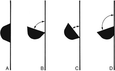
Figure 45-68 Blade angulation. A, 0 degrees: correct angulation for blade insertion. B, 45 to 90 degrees: correct angulation for scaling and root planing. C, Less than 45 degrees: incorrect angulation for scaling and root planing. D, More than 90 degrees: incorrect angulation for scaling and root planing, correct angulation for gingival curettage.
When gingival curettage is indicated, angulation greater than 90 degrees is deliberately established so that the cutting edge will engage and remove the pocket lining (Figure 45-68, D).
Lateral Pressure
Lateral pressure refers to the pressure created when force is applied against the surface of a tooth with the cutting edge of a bladed instrument. The exact amount of pressure applied must be varied according to the nature of the calculus and according to whether the stroke is intended for initial scaling to remove calculus or for root planing to smooth the root surface.
Lateral pressure may be firm, moderate, or light. When removing calculus, lateral pressure is initially applied firmly or moderately and is progressively diminished until light lateral pressure is applied for the final root-planing strokes. When insufficient lateral pressure is applied for the removal of heavy calculus, rough ledges or lumps may be shaved to thin, smooth sheets of burnished calculus that are difficult to detect and remove. This burnishing effect often occurs in areas of developmental depressions and along the cementoenamel junction.
Although firm lateral pressure is necessary for the thorough removal of calculus, indiscriminate, unwarranted, or uncontrolled application of heavy forces during instrumentation should be avoided. Repeated application of excessively heavy strokes often nicks or gouges the root surface.
The careful application of varied and controlled amounts of lateral pressure during instrumentation is an integral part of effective scaling and root-planing techniques and is critical to the success of both these procedures.
Strokes
Three basic types of strokes are used during instrumentation: the exploratory stroke, the scaling stroke, and the root-planing stroke. Any of these basic strokes may be activated by a pull or a push motion in a vertical, oblique, or horizontal direction (Figure 45-69). Vertical and oblique strokes are used most frequently. Horizontal strokes are used selectively on line angles or deep pockets that cannot be negotiated with vertical or oblique strokes. The direction, length, pressure, and number of strokes necessary for either scaling or root planing are determined by four major factors: (1) gingival position and tone, (2) pocket depth and shape, (3) tooth contour, and (4) the amount and nature of the calculus or roughness.
The exploratory stroke is a light, “feeling” stroke that is used with probes and explorers to evaluate the dimensions of the pocket and to detect calculus and irregularities of the tooth surface. With bladed instruments such as the curette, the exploratory stroke is alternated with scaling and root-planing strokes for these same purposes of evaluation and detection. The instrument is grasped lightly and adapted with light pressure against the tooth to achieve maximal tactile sensitivity.
The scaling stroke is a short, powerful pull stroke that is used with bladed instruments for the removal of both supragingival and subgingival calculus. The muscles of the fingers and hands are tensed to establish a secure grasp, and lateral pressure is firmly applied against the tooth surface. The cutting edge engages the apical border of the calculus and dislodges it with a firm movement in a coronal direction. The scaling motion should be initiated in the forearm and transmitted from the wrist to the hand with a slight flexing of the fingers. Rotation of the wrist is synchronized with movement of the forearm. The scaling stroke is not initiated in the wrist or fingers, nor is it carried out independently without the use of the forearm.
It is possible to initiate the scaling motion by rotating the wrist and forearm or by flexing the fingers. The use of wrist and forearm action versus finger motion has long been debated among clinicians. Perhaps the strong opinions on both sides should be the most valid indication that there is a time and a place for each. Neither method can be advocated exclusively because a careful analysis of effective scaling and root-planing technique reveals that both types of stroke activation are necessary for complete instrumentation. The wrist and forearm motion, pivoting in an arc on the finger rest, produces a more powerful stroke and is therefore preferred for scaling. Finger flexing is indicated for precise control over stroke length in areas such as line angles and when horizontal strokes are used on the lingual or facial aspects of narrow-rooted teeth.
The push scaling motion has been advocated by some clinicians. In the push stroke, the instrument engages the lateral or coronal border of the calculus, and the fingers provide a thrust motion that dislodges the deposit. Because the push stroke may force calculus into the supporting tissues, its use, especially in an apical direction, is not recommended.
The root-planing stroke is a moderate to light pull stroke that is used for final smoothing and planing of the root surface. Although hoes, files, and ultrasonic instruments have been used for root planing, curettes are widely acknowledged to be the most effective and versatile instruments for this procedure.* The design of the curette, which allows it to be more easily adapted to subgingival tooth contours, makes curettes particularly suitable for root planing in periodontal patients. With a moderately firm grasp, the curette is kept adapted to the tooth with even, lateral pressure. A continuous series of long, overlapping shaving strokes is activated. As the surface becomes smoother and resistance diminishes, lateral pressure is progressively reduced.
Instruments for Scaling and Root Planing
Universal Curettes
The working ends of the universal curette are designed in pairs so that all surfaces of the teeth can be treated with one double-ended instrument or a matched pair of single-ended instruments (see Figure 45-16).
In any given quadrant, when approaching the tooth from the facial aspect, one end of the universal curette adapts to the mesial surfaces, and the other end adapts to the distal surfaces. When approaching from the lingual aspect in the same quadrant, the double-ended universal curette must be turned end for end because the blades are mirror images. This means that the end that adapts to the mesial surfaces on the facial aspect also adapts to the distal surfaces on the lingual aspect, and vice versa. Both ends of the universal curette are used for instrumentation of the anterior teeth. On posterior teeth, however, because of the limited access to distal surfaces, a single working end can be used to treat both mesial and distal surfaces by using both its cutting edges. To do this, the instrument is first adapted to the mesial surface with the handle nearly parallel to the mesial surface. Because the face of the universal curette blade is honed at 90 degrees to the lower shank, if the lower shank is positioned so that it is absolutely parallel to the surface being instrumented, the tooth-blade angulation is 90 degrees. To close this angle and thus obtain proper working angulation, the lower shank must be tilted slightly toward the tooth. The distal surface of the same posterior tooth can be instrumented with the opposite cutting edge of the same blade. This cutting edge can be adapted at proper working angulation by positioning the handle so that it is perpendicular to the distal surface (Figure 45-70).
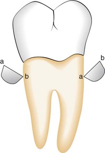
Figure 45-70 Adaptation of the universal curette on a posterior tooth. Cross-sectional representations of the same universal curette blade as its cutting edges (a and b) are adapted to the mesial and distal surfaces of a posterior tooth.
When adapting the universal curette blade, as much of the cutting edge as possible should be in contact with the tooth surface, except on narrow convex surfaces such as line angles. Although the entire cutting edge should contact the tooth, pressure should be concentrated on the lower third of the blade during scaling strokes. During root-planing strokes, however, lateral pressure should be distributed evenly along the cutting edge.
The primary advantage of these curettes is that they are designed to be used universally on all tooth surfaces, in all regions of the mouth. However, universal curettes have limited adaptability for the treatment of deep pockets in which apical migration of the attachment has exposed furcations, root convexities, and developmental depressions. For this reason, many clinicians prefer the Gracey curettes and the new modifications of Gracey curettes, which are area specific and specially designed for subgingival scaling and root planing in periodontal patients.
Gracey Curettes
As discussed earlier, Gracey curettes are a set of area-specific instruments that were designed by Dr. Clayton H. Gracey of Michigan in the mid-1930s (see Figure 45-18). Four design features make the Gracey curettes unique: (1) they are area specific, (2) only one cutting edge on each blade is used, (3) the blade is curved in two planes, and (4) the blade is “offset” (see Table 45-1.) Each of these features directly influences the manner in which the Gracey curettes are used, as discussed next.
Area Specificity
There are seven pairs of curettes in the set. The Gracey curettes #1-2 and 3-4 are used on anterior teeth. The Gracey #5-6 may be used on both anterior and premolar teeth. The facial and lingual surfaces of posterior teeth are instrumented with Gracey curettes #7-8 and 9-10. The Gracey #11-12 is designed for mesial surfaces of posterior teeth, and the #13-14 adapts to the distal surfaces of posterior teeth. Although these guidelines for areas of use were originally established by Dr. Gracey, it is possible to use a Gracey curette in an area of the mouth other than the one for which it was specifically designed if the general principles regarding these curettes are understood and applied. Gracey curettes need not be reserved exclusively for periodontal patients. In fact, many clinicians prefer Gracey curettes for general scaling because of their excellent adaptability.
Single Cutting Edge Used
As with a universal curette, the Gracey curette has a blade with two cutting edges. Unlike the universal curette, however, the Gracey instrument is designed so that only one cutting edge is used. To determine which of the two is the correct cutting edge to adapt to the tooth, the blade should be held face up and parallel to the floor. When viewed from this angle, the blade can be seen to curve to the side. One cutting edge forms a larger outer curve, and the other forms a shorter, small inner curve. The larger outer curve, which has also been described as the “inferior cutting edge” or as the cutting edge farther away from the handle, is the correct cutting edge (Figure 45-71).
Blade Curves in Two Planes
As with the toe of the universal curette, the toe of the Gracey curette curves upward. However, the toe of the Gracey curette also curves to the side, as previously mentioned. This unique curvature enhances the blade’s adaptation to convexities and concavities as the working end is advanced around the tooth. Only the lower third or half of the Gracey blade is in contact with the tooth during instrumentation. The cutting edge of a universal curette blade, on the other hand, is straight and does not curve to the side, making it less adaptable to root concavities.
Offset Blade
Gracey curette blades are honed at an offset angle, which means that the face of the blade is not perpendicular to the lower shank as it is on a universal curette. Instead, Gracey curettes are designed so that the tooth-blade working angulation is 60 to 70 degrees when the lower shank is held parallel to the tooth surface. Gracey curettes were originally designed to be used with push strokes and were beveled to provide a tooth-blade angulation of 40 degrees when the lower shank was parallel to the tooth surface; for many years, Gracey curettes were available only in this form. Currently, Gracey curettes are available not only in the original push design but also in a modified version to be used with pull strokes. It is important to understand this when purchasing Gracey curettes to avoid obtaining instruments that are not properly designed for pull strokes. If Gracey curettes that are designed to be used with push strokes are used with pull strokes instead, they are likely to burnish calculus rather than completely remove it. The design of the Gracey curette was modified in response to requests from clinicians who liked the shank design and adaptability of the original Gracey instruments but were opposed to the use of push strokes for scaling and root planing. The push stroke is not recommended, especially for the novice clinician, because it is likely to cause undue trauma to the junctional epithelium and to embed fragments of dislodged calculus in the soft tissues.
Principles of Use
The following general principles of use of the Gracey curettes are essentially the same as those for the universal curette; italicized principles apply only to Gracey curettes:
Extended-Shank Gracey Curettes
Extended-shank Gracey curettes, such as the After Five curettes, are 3 mm longer in the terminal shank than the standard Gracey curettes but are used with the same technique (see Figure 45-23). They are most useful for deep pockets on maxillary and mandibular posterior teeth, where the longer terminal shank allows better access, especially to deep mesial and distal pockets (see Figure 45-24). Although the longer lower shank makes access easier while using a conventional intraoral finger rest, the use of an extraoral fulcrum allows better access and adaptation to all the maxillary posterior teeth. Extended shank Gracey curettes with rigid shanks should be used for scaling of heavy calculus; those with regular, finishing shanks should be used for periodontal maintenance patients with deep residual pockets.
Mini-Bladed Gracey Curettes
Mini-bladed Gracey curettes, such as the Mini Five curettes and the Gracey Curvettes, have a terminal shank that is 3 mm longer than the standard Gracey curettes and a blade that is 50% shorter. Micro Mini Five curette blades are 20% smaller than Mini Five curette blades (see Figures 45-28 and 45-29). These mini-bladed instruments are generally used in the same manner as the Gracey curettes, except for the following specific differences:
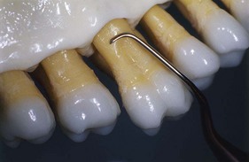
Figure 45-78 Mini Five 13/14 curette adapted to the palatal surface of a maxillary molar with the toe directed distally.
When properly used, mini-bladed Gracey curettes allow unprecedented access and effectiveness for both nonsurgical and surgical root debridement. One study showed that Gracey Curvettes performed better than standard Gracey curettes in deep anterior pockets.73 In areas such as line angles, furcations, and narrow, curved, facial, or palatal root surfaces, these miniature curettes provide excellent adaptation with better tactile sensitivity than modified, slim ultrasonic tips. Studies also demonstrated that Gracey Curvette curettes performed better than ultrasonic slim tips on deep mandibular anterior pockets, furcations, and furcation entrances.107,108 No comparison of hand instruments and modified, slim ultrasonic tips can be made unless mini-bladed curettes have been fully employed. To date, some research has been done to compare the effectiveness of mini-bladed instruments with the modified, slim ultrasonic tips. More of these studies need to be performed in vivo to guide clinicians in the optimal utilization of these newer types of instruments.112
Principles of Scaling and Root Planing*
Scaling is the process by which biofilm and calculus are removed from both supragingival and subgingival tooth surfaces. No deliberate attempt is made to remove tooth substance along with the calculus. Root planing is the process by which residual embedded calculus and portions of cementum are removed from the roots to produce a smooth, hard, clean surface.
The primary objective of scaling and root planing is to restore gingival health by completely removing elements that provoke gingival inflammation (i.e., biofilm, calculus, and endotoxin) from the tooth surface (Figure 45-79). Instrumentation has been shown to reduce dramatically the numbers of subgingival microorganisms and produce a shift in the composition of subgingival biofilm from one with high numbers of gram-negative anaerobes to one dominated by gram-positive facultative bacteria compatible with health.† After thorough scaling and root planing, a profound reduction in spirochetes, motile rods, and putative pathogens, such as Actinobacillus actinomycetemcomitans, Porphyromonas gingivalis, and Prevotella intermedia, and an increase in coccoid cells occur.‡ These changes in the microbiota are accompanied by a reduction or elimination of inflammation clinically.§ This positive microbial change must be sustained by the periodic scaling and root planing performed during supportive periodontal therapy.||
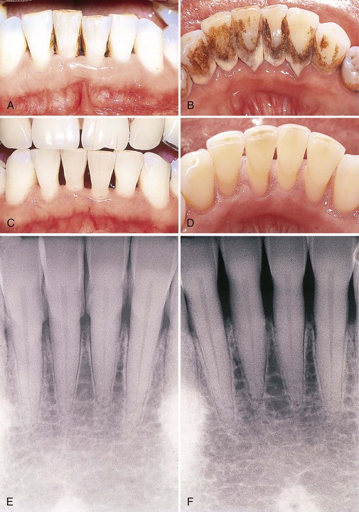
Figure 45-79 Results of Phase I therapy. A to F, Moderate chronic periodontitis. A, Patient presenting with moderate attachment loss and probe depths in the 4- to 6-mm range. Note the gingiva appears pink because it is fibrotic and the inflammation is deep in the periodontal pockets. B, Lingual view before treatment, with more visible inflammation and heavy deposits of calculus. C and D, The same areas with significant improvement in gingival health 18 months after scaling, root planing, and plaque control therapy were provided; the patient returned for regular maintenance visits. E and F, Presenting radiographs of the lower anterior teeth. Radiograph taken 18 months after Phase I therapy and maintenance shows no increase in bone loss.
†References 84, 87, 97, 123, 126, 136, and 138.
‡References 87, 123, 130, 136, 155, and 165.
§References 11, 45, 48, 62, 66, 85, 94, 116, 118, and 119.
||References 10, 18, 82, 85, 112, 136, and 160. Scaling and root planing are not separate procedures; all the principles of scaling apply equally to root planing. The difference between scaling and root planing is only a matter of degree. The nature of the tooth surface determines the degree to which the surface must be scaled or planed.
Biofilm and calculus on enamel surfaces provoke gingival inflammation. Unless they are grooved or pitted, enamel surfaces are relatively smooth and uniform. When biofilm and calculus form on enamel, the deposits are usually superficially attached to the surface and are not locked into irregularities. Scaling alone is sufficient to remove biofilm and calculus completely from enamel, leaving a smooth, clean surface.
Root surfaces exposed to biofilm and calculus pose a different problem. Deposits of calculus on root surfaces are frequently embedded in cemental irregularities.1,24,96,135,166 Subgingival calculus is porous and harbors bacteria and endotoxin and therefore should be removed completely.23,23a,149 When dentin is exposed, biofilm bacteria may invade dentinal tubules.1 Therefore scaling alone is insufficient to remove them, and a portion of the root surface must be removed to eliminate these deposits. Furthermore, when the root surface is exposed to biofilm and the pocket environment, its surface is contaminated by toxic substances, notably endotoxins.3,4,56 Evidence suggests that these toxic substances are only superficially attached to the root and do not permeate it deeply.¶ Removal of extensive amounts of dentin and cementum is not necessary to render the roots free of toxins and should be avoided.45,85,112 In areas where cementum is thin, however, instrumentation may expose dentin. Although this is not the aim of treatment, such exposure may be unavoidable.131,154
¶References 25, 26, 60, 61, 95, 99, 100, and 139. Scaling and root planing should not be viewed as separate procedures unrelated to the rest of the treatment plan. These procedures belong in the initial phase of an orderly sequence of treatment. After careful analysis of a case, the number of appointments needed to complete this phase of treatment is estimated. Patients with small amounts of calculus and relatively healthy tissues can be treated in one appointment. Most other patients require several treatment sessions. The dentist should estimate the number of appointments needed on the basis of the number of teeth in the mouth, severity of inflammation, amount and location of calculus, depth and activity of pockets, presence of furcation invasions, patient’s comprehension of and compliance with oral hygiene instructions, and need for local anesthesia.
When the rationale for scaling and root planing is thoroughly understood, it becomes apparent that mastery of these skills is essential to the ultimate success of any course of periodontal therapy. Of all clinical dental procedures, subgingival scaling and root planing in deep pockets are the most difficult and exacting skills to master. It has been argued that such proficiency in instrumentation cannot be attained, and therefore periodontal surgery is necessary to gain access to root surfaces. Others have argued that although proficiency is possible, it need not be developed because access to the roots can be gained more easily with surgery. However, without mastering subgingival scaling and root-planing skills, the clinician will be severely hampered and unable to treat adequately those patients for whom surgery is contraindicated.
Good visual and tactile detection skills are required for the accurate initial assessment of the extent and nature of deposits and root irregularities before scaling and root planing. Valid evaluation of results of instrumentation depends on these detection skills.
Visual examination of supragingival and subgingival calculus just below the gingival margin is not difficult with good lighting and a clean field. Light deposits of supragingival calculus are often difficult to see when they are wet with saliva. Compressed air may be used to dry supragingival calculus until it is chalky white and readily visible. Air also may be directed into the pocket in a steady stream to deflect the marginal gingiva away from the tooth so that subgingival deposits near the surface can be seen.
Tactile exploration of the tooth surfaces in subgingival areas of pocket depth, furcations, and developmental depressions is much more difficult than visual examination of supragingival areas and requires the skilled use of a fine-pointed explorer or probe. The explorer or probe is held with a light but stable modified pen grasp. This provides maximal tactile sensitivity for detection of subgingival calculus and other irregularities. The pads of the thumb and fingers, especially the middle finger, should perceive the slight vibrations conducted through the instrument shank and handle as irregularities in the tooth surface are encountered.
After a stable finger rest is established, the tip of the instrument is carefully inserted subgingivally to the base of the pocket. Light exploratory strokes are activated vertically on the root surface. When calculus is encountered, the tip of the instrument should be advanced apically over the deposit until the termination of the calculus on the root is felt. The distance between the apical edge of the calculus and the bottom of the pocket usually ranges from 0.2 to 1.0 mm. The tip is adapted closely to the tooth to ensure the greatest degree of tactile sensitivity and avoid tissue trauma. When a proximal surface is being explored, strokes must be extended at least halfway across that surface past the contact area to ensure complete detection of interproximal deposits. When an explorer is used at line angles, convexities, and concavities, the handle of the instrument must be rolled slightly between the thumb and fingers to keep the tip constantly adapted to the changes in tooth contour.
Although exploration technique and good tactile sensitivity are important, interpreting various degrees of roughness and making clinical judgments based on these interpretations also require much expertise. The beginning student usually has difficulty detecting fine calculus and altered cementum. Such detection must begin with the recognition of ledges, lumps, or spurs of calculus, then smaller spicules, then slight roughness, and finally a slight graininess that feels like a sticky coating or film covering the tooth surface. Overhanging or deficient margins of dental restorations, caries, decalcification, and root roughness caused by previous instrumentation are all typically found during exploration. These and other irregularities must be recognized and differentiated from subgingival calculus. Because this requires a great deal of experience and a high degree of tactile sensitivity, many clinicians agree that the development of detection skills is as important as the mastery of scaling and root-planing technique.
Supragingival Scaling Technique
Supragingival calculus is generally less tenacious and less calcified than subgingival calculus. Because instrumentation is performed coronal to the gingival margin, scaling strokes are not confined by the surrounding tissues. This makes adaptation and angulation easier. It also allows direct visibility, as well as a freedom of movement not possible during subgingival scaling.
Sickles, curettes, and ultrasonic and sonic instruments are most often used for the removal of supragingival calculus; hoes and chisels are less frequently used. To perform supragingival scaling, the sickle or curette is held with a modified pen grasp, and a firm finger rest is established on the teeth adjacent to the working area. The blade is adapted with an angulation of slightly less than 90 degrees to the surface being scaled. The cutting edge should engage the apical margin of the supragingival calculus while short, powerful, overlapping scaling strokes are activated coronally in a vertical or an oblique direction. The sharply pointed tip of the sickle can easily lacerate marginal tissue or gouge exposed root surfaces, so careful adaptation is especially important when this instrument is being used. The tooth surface is instrumented until it is visually and tactilely free of all supragingival deposits. If the tissue is retractable enough to allow easy insertion of the bulky blade, the sickle may be used slightly below the free gingival margin. If the sickle is used in this manner, final scaling and root planing with the curette should always follow.
Subgingival Scaling and Root-Planing Technique
Subgingival scaling and root planing are much more complex and difficult to perform than supragingival scaling. Subgingival calculus is usually harder than supragingival calculus and is often locked into root irregularities, making it more tenacious and therefore more difficult to remove.24,96,135,166 The overlying tissue creates significant problems in subgingival instrumentation. Vision is obscured by the bleeding that inevitably occurs during instrumentation and by the tissue itself. The clinician must rely heavily on tactile sensitivity to detect calculus and irregularities, guide the instrument blade during scaling and root planing, and evaluate the results of instrumentation.
In addition, the adjacent pocket wall limits the direction and length of the strokes. The confines of the soft tissue make careful adaptation to tooth contours imperative to avoid trauma. Such precise adaptation cannot be accomplished without a thorough knowledge of tooth morphologic features. The clinician must form a mental image of the tooth surface to anticipate variations in contour, continually confirming or modifying the image in response to tactile sensations and visual cues, such as the position of the instrument handle and shank. The clinician then must instantaneously adjust the adaptation and angulation of the working end to the tooth. It is this complex and precise coordination of visual, mental, and manual skills that makes subgingival instrumentation one of the most difficult of all dental skills. The curette is preferred by most clinicians for subgingival scaling and root planing because of the advantages afforded by its design. Its curved blade, rounded toe, and curved back allow the curette to be inserted to the base of the pocket and adapted to variations in tooth contour with minimal tissue displacement and trauma.
Sickles, hoes, files, and ultrasonic instruments also are used for subgingival scaling of heavy calculus. Some small files (e.g., Hirschfeld file) may be inserted to the base of the pocket to crush or initially fracture tenacious deposits. Larger files, hoes, sickles, and standard ultrasonic tips for supragingival use are too bulky and cannot be inserted easily into deep pockets or areas where tissue is firm and fibrotic. Hoes and files cannot be used to produce as smooth a surface as curettes. Hoes, files, and standard large ultrasonic tips are all more hazardous than the curette in terms of trauma to the root surface and surrounding tissues.15,105,131 Although thin ultrasonic tips designed for scaling of deep pockets and furcations can be inserted more easily subgingivally, they must be used on low power.39,40,57 When low-power scaling is performed on heavy calculus or tenacious sheets of calculus, thin ultrasonic tips are likely to burnish the calculus rather than thoroughly remove it. Therefore ultrasonic scaling should be followed by careful assessment with an explorer and further instrumentation with curettes when necessary.
Subgingival scaling and root planing are accomplished with either universal or area-specific (Gracey) curettes using the following basic procedure. The curette is held with a modified pen grasp, and a stable finger rest is established. The correct cutting edge is slightly adapted to the tooth, with the lower shank kept parallel to the tooth surface. The lower shank is moved toward the tooth so that the face of the blade is nearly flush with the tooth surface. The blade is then inserted under the gingiva and advanced to the base of the pocket by a light exploratory stroke. When the cutting edge reaches the base of the pocket, a working angulation of between 45 and 90 degrees is established, and pressure is applied laterally against the tooth surface. Calculus is removed by a series of controlled, overlapping, short, powerful strokes primarily using wrist-arm motion (Figure 45-80). As calculus is removed, resistance to the passage of the cutting edge diminishes until only a slight roughness remains. Longer, lighter root-planing strokes are then activated with less lateral pressure until the root surface is completely smooth and hard. The instrument handle must be rolled carefully between the thumb and fingers to keep the blade adapted closely to the tooth surface as line angles, developmental depressions, and other changes in tooth contour are followed. Scaling and root-planing strokes should be confined to the portion of the tooth where calculus or altered cementum is found; this area is known as the instrumentation zone. Sweeping the instrument over the crown where it is not needed wastes operating time, dulls the instrument, and causes loss of control.
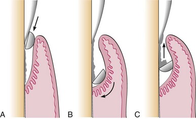
Figure 45-80 Subgingival scaling procedure. A, Curette inserted with the face of the blade flush against the tooth. B, Working angulation (45-90 degrees) is established at the base of the pocket. C, Lateral pressure is applied, and the scaling stroke is activated in the coronal direction.
The amount of lateral pressure applied to the tooth surface depends on the nature of the calculus and whether the strokes are for initial calculus removal or final root planing. If heavy lateral pressure is continued after the bulk of calculus has been removed and the blade is repeatedly readapted with short, choppy strokes, the result will be a root surface roughened by numerous nicks and gouges, resembling the rippled surface of a washboard.111 If heavy lateral pressure is continued with long, even strokes, the result will be excessive removal of root structure, producing a smooth but “ditched” or “riffled” root surface. To avoid these hazards of overinstrumentation, a deliberate transition from short, powerful scaling strokes to longer, lighter root-planing strokes must be made as soon as the calculus and initial roughness have been eliminated.
When scaling strokes are used to remove calculus, force can be maximized by concentrating lateral pressure onto the lower third of the blade (see Figure 45-66). This small section, the terminal few millimeters of the blade, is positioned slightly apical to the lateral edge of the deposit, and a short vertical or oblique stroke is used to split the calculus from the tooth surface. Without withdrawing the instrument from the pocket, the lower third of the blade is advanced laterally and repositioned to engage the next portion of the remaining deposit. Another vertical or oblique stroke is made, slightly overlapping the previous stroke. This process is repeated in a series of powerful scaling strokes until the entire deposit has been removed. The overlapping of these pathways or “channels” of instrumentation111 ensures that the entire instrumentation zone is covered (Figure 45-81).
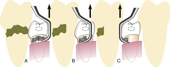
Figure 45-81 Instrumentation for calculus removal. A, Calculus is removed by engaging the apical or lateral edge of the deposit with the cutting edge of a scaler; vertical movement of the instrument will remove the fragment of calculus engaged by the instrument, as seen in the shaded drawing. B, The instrument is moved laterally and again engages the edge of the calculus, overlapping the previous stroke to some extent; the shaded drawing shows further removal. C, The final portion of the deposit is engaged and removed. Note how the procedure is performed in an interdental space by entering facially and lingually.
Engaging a large, tenacious ledge or piece of calculus with the entire length of the cutting edge is not recommended because the force is distributed through a longer section of the cutting edge rather than concentrated. Much more lateral pressure is required to dislodge the entire deposit in one stroke. Although some clinicians may possess the strength to remove calculus completely in this manner, the heavier forces required diminish tactile sensitivity and contribute to a loss of control that results in tissue trauma. A single heavy stroke usually is not sufficient to remove calculus entirely. Instead, the blade skips over or skims the surface of the deposit. Subsequent strokes made with the entire cutting edge tend to shave the deposit down layer by layer. When a series of these repeated whittling strokes is applied, the calculus may be reduced to a thin, smooth, burnished sheet that is difficult to distinguish from the surrounding root surface.
A common error in instrumenting proximal surfaces is failing to reach the midproximal region apical to the contact. This area is relatively inaccessible, and the technique requires more skill than instrumentation of buccal or lingual surfaces. It is extremely important to extend strokes at least halfway across the proximal surface so that no calculus or roughness remains in the interproximal area. With properly designed curettes, this can be accomplished by keeping the lower shank of the curette parallel with the long axis of the tooth (Figure 51-82, A). With the lower shank parallel to the long axis, the blade of the curette will reach the base of the pocket and the toe will extend beyond the midline as strokes are advanced across the proximal surface. This extension of strokes beyond the midline ensures thorough exploration and instrumentation of these surfaces. If the lower shank is angled or tilted away from the tooth, the toe will move toward the contact area. Because this prevents the blade from reaching the base of the pocket, calculus apical to the contact will not be detected or removed. Strokes will be hampered because the toe tends to become lodged in the contact. If the instrument is angled or tilted too far toward the tooth, the lower shank will hit the tooth or the contact area, preventing extension of strokes to the midproximal region (Figure 45-82, B and C).
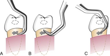
Figure 45-82 Shank position for scaling proximal surfaces. A, Correct shank position, parallel with the long axis of the tooth. B, Incorrect shank position, tilted away from the tooth. C, Incorrect shank position, tilted too far toward the tooth. Sextant: lingual aspect.
The relationship between the location of the finger rest and the working area is important for two reasons. First, the finger rest or fulcrum must be positioned to allow the lower shank of the instrument to be parallel or nearly parallel to the tooth surface being treated. This parallelism is a fundamental requirement for optimal working angulation. Second, the finger rest must be positioned to enable the operator to use wrist-arm motion to activate strokes. On some aspects of the maxillary posterior teeth, these requirements can be met only with the use of extraoral or opposite-arch fulcrums. When intraoral finger rests are used in other regions of the mouth, the finger rest must be close enough to the working area to fulfill these two requirements. A finger rest that is established too far from the working area forces the clinician to separate the middle finger from the fourth finger in an effort to obtain parallelism and proper angulation. Effective wrist-arm motion is possible only when these two fingers are kept together in a built-up fulcrum. Separation of the fingers commits the clinician to the exclusive use of finger flexing for the activation of strokes.
As instrumentation proceeds from one tooth to the next, the body position of the operator and the location of the finger rest must be frequently adjusted or changed to allow parallelism and wrist-arm motion. Various approaches to instrumentation in different areas of the mouth are illustrated here. The examples shown provide maximal efficiency for the clinician and comfort for the patient. For most areas, more than one approach is presented. Other approaches are possible and are acceptable if they provide equal efficiency and comfort. The following approaches may be used:
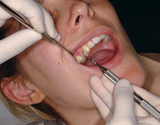
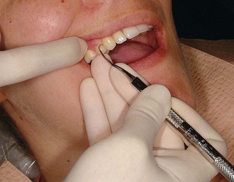
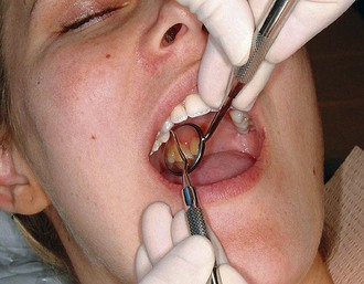
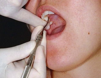
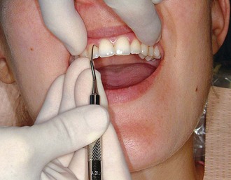
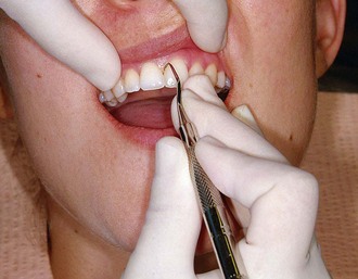
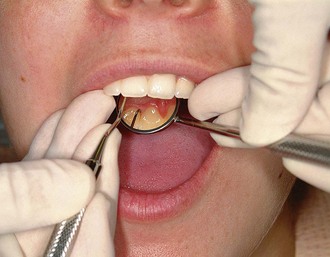
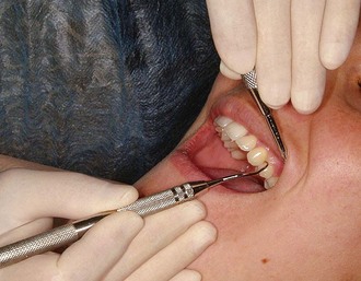
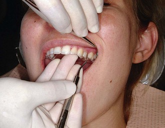
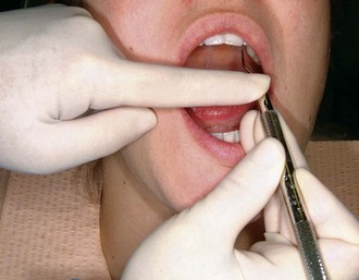
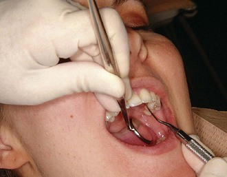
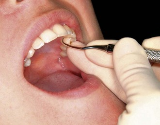
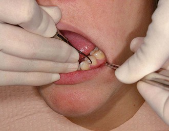
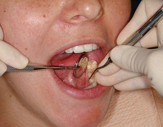
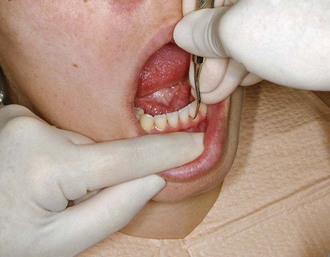
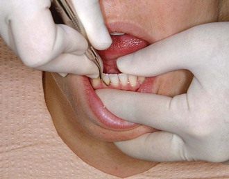
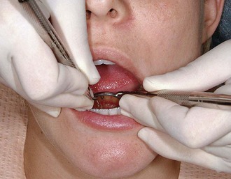
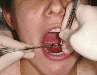
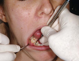
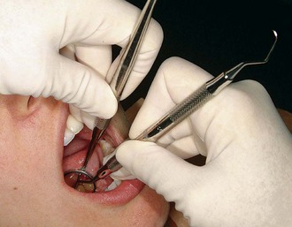
Instruments
Ultrasonic scalers may be used for removing plaque and stain, scaling, root planing, curetting, and surgical debridement. The two types of ultrasonic units are magnetostrictive and piezoelectric. In both types, alternating electrical current generates oscillations in materials in the handpiece that cause the scaler tip to vibrate. Depending on the manufacturer, these ultrasonic vibrations at the tip of the instruments of both types range from 18,000 to 50,000 cycles per second (cps; also referred to as Hertz [Hz]). In magnetostrictive units the pattern of vibration of the tip is elliptical, which means that all sides of the tip are active and will work when adapted to the tooth. In piezoelectric units the pattern of vibration of the tip is linear, or back and forth, meaning that the two sides of the tip are the most active.
Sonic units consist of a handpiece that attaches to a compressed-air line and uses a variety of specially designed tips. Vibrations at the sonic tip range from 2500 to 7000 cps, which provides less power for calculus removal than ultrasonic units.
Ultrasonic and sonic tips of different shapes and sizes are available. Larger tips are used for removal of heavy supragingival calculus and heavy subgingival calculus where tissue is inflamed and retractable. Thinner tips are designed for more definitive subgingival debridement. All tips are designed to operate in a wet field with a water spray directed at the end of the tip. Vibrational energy dislodges calculus and biofilm from the tooth surfaces and acoustic streaming and acoustic turbulance of the water serves to flush these deposits from the pocket. Magnetostrictive ultrasonic inserts generate heat and require water for cooling. Sonic and piezoelectric units do not generate heat but still utilize water for cooling of frictional heat and for flushing away debris.
Ultrasonic instruments have been used as a valuable adjunct to conventional hand instrumentation for many years. In the early era of ultrasonic scaling, most tips were large and bulky, making them generally suitable only for supragingival scaling. Currently, many thinner ultrasonic tips allow better access to subgingival areas that were previously accessible only with hand instruments.38 It is important to understand this historical perspective when attempting to interpret the literature comparing the effects of hand and ultrasonic instruments on root surfaces. Earlier studies using older tip designs generally showed that ultrasonic instruments left a rougher, more damaged surface than curettes.* More recent studies, especially those using the newer, thinner tips, show that ultrasonic instruments can produce root surfaces as smooth or smoother than those produced by curettes.38,39,44,124 Whether these relative degrees of smoothness are important has not been clearly established.† It is evident, however, that both methods of instrumentation are able to provide satisfactory clinical results, as measured by removal of biofilm and calculus, reduction of bacteria, reduction of inflammation and pocket depth, and gain in clinical attachment.‡
Ultrasonic instruments have been shown to be more effective than hand instruments at reducing spirochetes and motile rods in class II and III furcations.78 Two in vitro studies found that ultrasonic and sonic scalers do not kill periodontal pathogenic bacteria by cavitation, rather they suggest an antimicrobial effect from an increase in temperature or from acoustic streaming.102,132 Other in vitro studies found that the mini-bladed Gracey curvettes were more effective than slim ultrasonic inserts in debriding root trunks, furcation entrances, and furcation areas of mandibular first molars.107,108 Mini-bladed hand instruments—such as the Gracey curvettes and the mini-bladed or micro mini-bladed Gracey curvettes—allow excellent, unprecedented access to narrow furcations and they can be followed by thin, curved ultrasonic inserts for final debridement and lavage.
The selection of either ultrasonic or hand instrumentation should be determined by the clinician’s preference and experience and the needs of each patient. The success of either treatment method is determined by the time devoted to the procedure and the thoroughness of root debridement. In practice, clinicians typically use a combination of both ultrasonic and hand instrumentation to achieve thorough debridement.
The vibrational energy produced by the ultrasonic instrument makes it useful for removing heavy, tenacious deposits of calculus and stain. Such deposits can be removed more quickly and with less effort ultrasonically than manually. When ultrasonic instruments are properly manipulated, less tissue trauma and, therefore, less postoperative discomfort occur. This makes ultrasonic instrumentation useful for initial debridement in patients with acute painful conditions such as necrotizing ulcerative gingivitis. This same quality can be used to advantage with the new, thin ultrasonic tips for subgingival root debridement and deplaquing in maintenance patients with residual pocket depth. Ultrasonic scaling devices also have been used for gingival curettage and to remove overhangs and excess cement after cementing orthodontic appliances. Opinions differ regarding the effectiveness of ultrasonic instruments for removing stain compared with conventional polishing methods.22
There are some contraindications for the use of ultrasonic and sonic scaling devices. Magnetostrictive devices have been reported to interfere with the function of older cardiac pacemakers.167 In a recent independent study, a piezoelectric dental scaler produced no electromagnetic interference with defibrillators.20a Patients with newer pacemakers can be treated safely; however, there may be a risk if the patient is medically fragile or if electronically defective ultrasonic devices are used.90,152,167 Medical consultation is advised when treating patients with such conditions.
Patients with known communicable diseases that can be transmitted by aerosols should not be treated with ultrasonic or sonic scaling devices. The water spray creates a contaminated aerosol that fills the operating area, exposing personnel and surfaces.74,98 Even when treating patients without known communicable diseases, it is especially important that proper infection control measures be observed (i.e., use of protective clothing, eyewear, masks, and gloves) and proper surface decontamination be performed afterward. Prerinsing for 1 minute with an antimicrobial mouthwash such as 0.12% chlorhexidine significantly reduces the number of bacteria in the aerosol for approximately 1 hour.156
Patients at risk for respiratory disease should not be treated with ultrasonic or sonic devices, including patients who are immunosuppressed or have chronic pulmonary disorders.137,148 Finally, metal ultrasonic and sonic inserts are contraindicated for titanium implants, which can be etched or gouged, and for porcelain or bonded restorations, which can be fractured or removed.20,37,75,120,157 Magnetostrictive and piezoelectric plastic-tipped ultrasonic inserts that do not cause damage to titanium implants are available.72 Also, plastic and Teflon-coated sonic scaler tips have been developed for titanium implants and for deplaquing and subgingival polishing of root surfaces.69,70,128
Technique
Ultrasonic instrumentation is accomplished with a light-to-moderate grasp and varying pressures depending on the amount and tenacity of the deposit. Excessive pressure is not recommended because it can cause dampening of the vibration of the tip. The tip should be kept constantly in motion and parallel to the tooth surface.39,57,115 Leaving the tip in one place for too long or using the point of the tip against the tooth can produce gouging and roughening of the root surface or overheating of the tooth.38 Using a lower-power setting and applying only slight pressure reduces the volume and depth of tooth structure removal.29,115
The ultrasonic tip must come in direct physical contact with calculus to fracture and remove it. The tip must also contact all aspects of the root surface to remove biofilm and toxins thoroughly. Although as much as 10 mm or more of the length of the ultrasonic tip vibrates, only the terminal few millimeters of the tip produce maximum vibration. At any point in time, it is only possible for this terminal 1 to 2 millimeter portion of the tip to be in contact with the tooth because of the curved anatomy of the tooth. A series of focused, overlapping strokes must be activated to keep this small active portion of the tip adapted to the root surface at all times.57 The handpiece and the blunt working end of the ultrasonic tip impair tactile sensitivity, and the constant water spray hampers visibility. For these reasons, during ultrasonic instrumentation, the tooth surface should be frequently examined with an explorer to evaluate the completeness of debridement.
The aerosol produced by sonic and ultrasonic instrumentation may contain potentially infectious blood-borne and airborne pathogens.* Pneumococci, staphylococci, α-hemolytic streptococci, and Mycobacterium tuberculosis are among the bacteria that have been found in dental aerosols.65,79 Aerosols also subject dental personnel and patients to many viruses, including herpes simplex, hepatitis, influenza, common cold, Epstein-Barr, and cytomegalovirus.27,30-33,89,150 Of additional concern are pathogens that do not originate from patients but are from the contaminated waterlines of the dental unit or the ultrasonic device.34,42,109 Putative pathogens such as Pseudomonas species and Legionella pneumophila have been isolated from dental unit water and can become aerosolized by an ultrasonic scaler.34,42,49,104 Aerosol from ultrasonic instrumentation always contains blood14,91 and lingers in the air for 30 minutes or longer in the entire operatory and in areas of the dental office outside the operatory.74,76,92,93 Unprotected patients may be more susceptible to infection from the aerosol than dental personnel who are wearing protective barriers, such as masks, gloves, eyewear, and clinical clothing.16,27,137 High-speed evacuation, preprocedural rinsing with chlorhexidine, flushing of the handpiece and waterlines or a self-contained sterile water source, thorough disinfection of environmental surfaces, and adequate ventilation and air filtration units with high-efficiency particulate air (HEPA) filters are all important precautions to minimize the potential hazards of ultrasonic aerosols.53-55129
With these points in mind, the ultrasonic device is used in the following manner:
See Chapter 46 for additional information on ultrasonic and sonic scaling.
The adequacy of scaling and root planing is evaluated when the procedure is performed and again later, after a period of soft tissue healing.
Immediately after instrumentation, the tooth surfaces should be carefully inspected visually with optimal lighting and the aid of a mouth mirror and compressed air; surfaces also should be examined with a fine explorer or probe. Subgingival surfaces should be hard and smooth. Although complete removal of calculus is definitely necessary for the health of the adjacent soft tissue,160 little documented evidence of the necessity for root smoothness is available.45,48,151 Nevertheless, relative smoothness is still the best immediate clinical indication that calculus has been completely removed.45
Although smoothness is the criterion by which scaling and root planing are immediately evaluated, the ultimate evaluation is based on tissue response.158 Clinical evaluation of the soft tissue response to scaling and root planing, including probing, should not be conducted earlier than 2 weeks postoperatively. Reepithelialization of the wounds created during instrumentation takes 1 to 2 weeks.117,143,144 Until then, gingival bleeding on probing can be expected even when calculus has been completely removed because the soft tissue wound is not epithelialized. Any gingival bleeding on probing noted after this interval is more likely the result of persistent inflammation produced by residual deposits not removed during the initial procedure or inadequate plaque control. Positive clinical changes after instrumentation often continue for weeks or months. Therefore a longer period of evaluation may be indicated before deciding whether to intervene with further instrumentation or surgery.28
Occasionally, the clinician may find that some slight root roughness remains after scaling and root planing.37,89,100 If sound principles of instrumentation have been followed, the roughness may not be calculus. Because calculus removal, not root smoothness, has been shown to be necessary for tissue health, it might be more prudent in such a case to stop short of perfect smoothness and reevaluate the patient’s tissue response after 2 to 4 weeks or longer. This avoids overinstrumentation and removal of excessive root structure in the pursuit of smoothness for its own sake. If the tissue is healthy after an interval of 2 to 4 weeks or longer, no further root planing is necessary. If the tissue is inflamed, the clinician must determine to what extent this is caused by biofilm accumulation or the presence of residual calculus and to what degree further root planing is necessary.
Instrument Sharpening
It is impossible to carry out periodontal procedures efficiently with dull instruments. A sharp instrument cuts more precisely and quickly than a dull instrument. To do its job at all, a dull instrument must be held more firmly and pressed harder than a sharp instrument. This reduces tactile sensitivity and increases the possibility that the instrument will inadvertently slip. Therefore, to avoid wasting time and operating haphazardly, clinicians must be thoroughly familiar with the principles of sharpening and able to apply them to produce a keen cutting edge on the instruments they are using. Development of this skill requires patience and practice, but clinical excellence cannot be attained without it.
Evaluation of Sharpness
The cutting edge of an instrument is formed by the angular junction of two surfaces of its blade. The cutting edges of a curette, for example, are formed where the face of the blade meets the lateral surfaces (Figure 45-103).
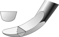
Figure 45-103 The cutting edge of a curette is formed by the angular junction of the face and the lateral surfaces of the instrument. When the instrument is sharp, the cutting edge is a fine line.
When the instrument is sharp, this junction is a fine line running the length of the cutting edge. As the instrument is used, metal is worn away at the cutting edge, and the junction of the face and lateral surface becomes rounded or dulled6,81 (Figure 45-104). Thus the cutting edge becomes a rounded surface rather than an acute angle, which is why a dull instrument cuts less efficiently and requires more pressure to do its job.46

Sharpness can be evaluated by sight and touch in one of the following ways:
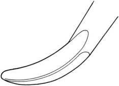
Objective of Sharpening
The objective of sharpening is to restore the fine, thin, linear cutting edge of the instrument. This is done by grinding the surfaces of the blade until their junction is once again sharply angular rather than rounded. For any given instrument, several sharpening techniques may produce this result. A technique is acceptable if it produces a sharp cutting edge without unduly wearing the instrument or altering its original design. To maintain the original design, the operator must understand the location and course of the cutting edges and the angles between the surfaces that form them. It is important to restore the cutting edge without distorting the original angles of the instrument. When these angles have been altered, the instrument does not function as it was designed to function, which limits its effectiveness.
Sharpening Stones
Sharpening stones may be quarried from natural mineral deposits or produced artificially. In either case, the surface of the stone is made up of abrasive crystals that are harder than the metal of the instrument to be sharpened. Coarse stones have larger particles and cut more rapidly; they are used on instruments that are dull. Finer stones with smaller crystals cut more slowly and are reserved for final sharpening to produce a finer edge and for sharpening instruments that are only slightly dull.127,140 India and Arkansas oilstones are examples of natural abrasive stones. Carborundum, ruby, and ceramic stones are synthetically produced (Figure 45-106).
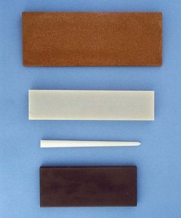
Figure 45-106 Sharpening stones. Top to bottom, A flat India stone, a flat Arkansas stone, a cone-shaped Arkansas stone, and a ceramic stone.
Sharpening stones can also be categorized by their method of use.
These stones are mounted on a metal mandrel and used in a motor-driven handpiece. They may be cylindrical, conical, or disc shaped. These stones are generally not recommended for routine use because they (1) are difficult to control precisely and can ruin the shape of the instrument, (2) tend to wear down the instrument quickly, and (3) can generate considerable frictional heat, which may affect the temper of the instrument.
Unmounted stones come in a variety of sizes and shapes. Some are rectangular with flat or grooved surfaces, whereas others are cylindrical or cone shaped. Unmounted stones may be used in two ways: the instrument may be stabilized and held stationary while the stone is drawn across it, or the stone may be stabilized and held stationary while the instrument is drawn across it.
Principles of Sharpening
Sharpening Individual Instruments
Several techniques will produce a properly sharpened curette. Regardless of the technique used, the clinician must keep in mind that the angle between the face of the blade and the lateral surface of any curette is 70 to 80 degrees (Figure 45-107). This is the most effective design for removing calculus and root planing (Figure 45-108, left). Changing this angle distorts the design of the instrument and makes it less effective. A cutting edge of less than 70 degrees is quite sharp but also thin (Figure 45-108, center). It wears down quickly and becomes dull. A cutting edge of 90 degrees or more requires heavy lateral pressure to remove deposits (Figure 45-108, right). Calculus removal with such an instrument is often incomplete, and root planing cannot be done effectively.
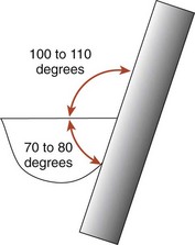
Figure 45-107 When the sharpening stone forms a 100- to 110-degree angle with the face of the blade, the 70- to 80-degree angle between the face and the lateral surface is automatically preserved.

Figure 45-108 Left, Properly sharpened curette maintains a 70- to 80-degree angle between its face and lateral surface. Center, Curette has been sharpened so that one of its cutting edges is less than 70 degrees. This fine edge is quite sharp but dulls easily. Right, One of the cutting edges of the curette has been sharpened to 90 degrees. Heavy lateral pressure must be applied to the tooth to remove deposits with such an instrument.
The following technique is recommended because it enables the clinician to visualize the critical 70- to 80-degree angle easily and thereby consistently restores an effective cutting edge:
Sharpening the Lateral Surface
When a flat, handheld stone is correctly applied to the lateral surface of a curette to maintain the 70- to 80-degree angle, the angle between the face of the blade and the surface of the stone will be 100 to 110 degrees (see Figure 45-107). This can best be visualized by holding the curette so that the face of the blade is parallel with the floor. A palm grasp should be used and the upper arm braced against the body for support.
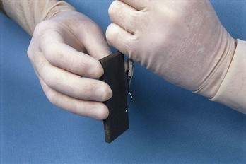
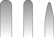
Sharpening the Face of the Blade
This may be done by moving a handheld cylindrical or cone-shaped stone back and forth across the face of the blade. A similar stone mounted in a handpiece may also be used by applying it to the face of the blade with the stone rotating toward the toe. These methods are not recommended for routine use for the following reasons:
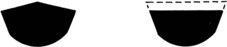
Area-Specific (Gracey) Curettes
As with a universal curette, a Gracey curette has an angle of 70 to 80 degrees between the face and lateral surface of its blade. Therefore the technique described for sharpening a universal curette can be used to sharpen a Gracey curette. However, several unique design features that distinguish a Gracey from a universal curette must be understood to avoid distorting the design of the instrument while sharpening (see earlier discussion).
As previously noted, Gracey curettes have an offset blade; that is, the face of the blade is not perpendicular to the shank of the instrument, as it is on a universal curette but is offset at a 70-degree angle (Figure 45-112). A Gracey curette is further distinguished by the curvature of its cutting edges. When viewed from directly above the face of the blade, the cutting edges of a universal curette extend in straight lines from shank to toe; both cutting edges can be used for scaling and root planing. The cutting edges of a Gracey curette, on the other hand, curve gently from shank to toe, and only the larger, outer cutting edge is used for scaling and root planing (Figure 45-113).
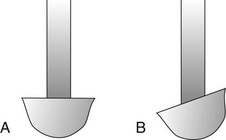
Figure 45-112 A, Face of a universal curette is at 90 degrees to its shank. B, Face of a Gracey curette is offset, forming a 70-degree angle with its shank.
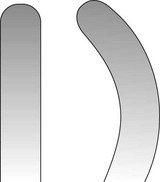
Figure 45-113 Cutting edges of a universal curette extend straight from shank to toe. The cutting edges of a Gracey curette gently curve from shank to toe. Only the larger, outer cutting edge at the right is used for scaling and needs to be sharpened.
With these points in mind, a Gracey curette is sharpened in the following manner:
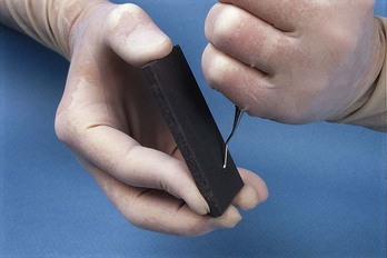
Figure 45-114 Note that when a Gracey curette is held in proper sharpening position, its shank is not perpendicular to the floor because of its offset blade angle. The stone meets the blade at an angle of 100 to 110 degrees. Compare this position with the sharpening position of a universal curette, as shown in Figure 45-109.
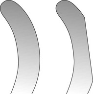
Extended-Shank and Mini-Bladed Gracey Curettes
Extended-shank Gracey curettes, such as the After Five curettes, are sharpened in exactly the same manner as the standard Gracey curettes. Although the terminal shank is 3 mm longer, the blade size and shape are very similar, and thus there is no difference in the sharpening technique.
Mini-bladed Gracey curettes, such as the Mini Five curettes, Micro Mini curettes, or Gracey Curvettes, are also sharpened with the same technique. These blades are only half the length of a standard Gracey blade, but the angle between the face and the lateral surface of the blade is still 70 to 80 degrees. However, sharpening too heavily or too often around the toe of a mini-bladed curette should be avoided to prevent excessive shortening of the blade.
The two types of sickle scalers are the straight sickle and curved sickle. On a straight sickle the face of the blade is flat from shank to tip, whereas on a curved sickle the face of the blade forms a gentle curve (Figure 45-116). However, the straight and curved sickles have similar cross-sectional designs. As in the curette, the angle between the face of the blade and the lateral surface of a sickle is 70 to 80 degrees (Figure 45-117). When a sharpening stone is correctly applied to the lateral surface to preserve this angle, the angle between the face of the blade and the surface of the stone is 100 to 110 degrees. With this in mind, the sickle scaler can be sharpened in a manner similar to that described for the curette, except that the sickle has a sharp, pointed toe that must not be rounded.
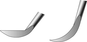
Figure 45-116 Face of the blade on a straight sickle is flat from shank to tip (left), whereas on the curved sickle the blade face forms a gentle arc (right).
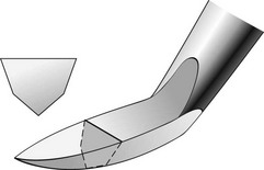
Figure 45-117 As with the curette, the sickle has an angle of 70 to 80 degrees between the face of the blade and the lateral surface.
A large, flat stone may also be used to sharpen sickles (Figure 45-118). The stone is stabilized on a table or cabinet with the left hand. The sickle is held in the right hand with a modified pen grasp and applied to the stone so that the angle between the face of the blade and the stone is 100 to 110 degrees. The fourth finger is placed on the right-hand edge of the stone to stabilize and guide the sharpening movement. The right hand then pushes and pulls the sickle across the surface of the stone.
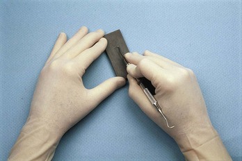
Figure 45-118 Large, flat stone may also be used to sharpen the sickle. The stone is stabilized on a flat surface. The fourth finger of the right hand guides the sharpening stroke as the instrument is pulled across the face of the stone toward the operator.
To avoid a wire edge, the operator finishes with a pull stroke, being sure that the proper angulation is always maintained.
Chisels have a single, straight cutting edge that is perpendicular to the shank. The face of the blade is continuous with the shank of the instrument, which may be directly in line with the handle or slightly curved. The end of the blade is beveled at 45 degrees to form the cutting edge.
To sharpen a chisel, stabilize a flat sharpening stone on a flat surface. Grasp the instrument with a modified pen grasp. Establish a finger rest with the pads of the third and fourth fingers against the straight edge of the sharpening stone. Apply the flat beveled surface of the chisel to the surface of the stone. If the entire surface of the bevel is contacting the stone, the 45-degree angle between the beveled surface and the face of the blade will be maintained, and the design of the instrument will not be altered (Figures 45-119 and 45-120).
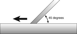
Figure 45-119 When the entire bevel on a chisel contacts the sharpening stone, the angle between the instrument and the stone is 45 degrees. The cutting edge will be properly sharpened if this angle is maintained as the instrument is pushed across the stone.
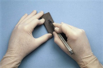
Using moderate, steady pressure, with the hand and arm acting as a unit and the finger resting on the edge of the stone as a guide, push the instrument across the surface of the sharpening stone. Release pressure slightly, and draw the instrument back to its starting point. Repeat the sharpening stroke until a sharp edge has been obtained. Remember to finish with a push stroke to prevent the formation of a wire edge. Check for sharpness as previously described. Examine the instrument carefully to be sure that its design has not been inadvertently altered.
Back-action surgical chisels and hoe scalers are sharpened with exactly the same technique described for chisels except that a pull stroke is used rather than a push stroke (Figure 45-121).
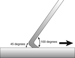
There are two general types of periodontal knives. The first type includes the disposable scalpel blades that come prepackaged and are presharpened and sterilized by the manufacturer. These knives are not resharpened when they become dull but are discarded and replaced.
The second type of periodontal knife is reusable and must be sharpened when it becomes dull. The most common knives in this group are the flat-bladed gingivectomy knives (e.g., Kirkland knives #15K and 16K) and the narrow, pointed interproximal knives.
Flat-Bladed Gingivectomy Knives
These knives have broad, flat blades that are nearly perpendicular to the lower shank of the instrument. The curved cutting edge extends around the entire outer edge of the blade and is formed by bevels on both the front and the back surface of the blade (Figure 45-122).
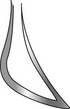
Figure 45-122 Flat-bladed gingivectomy knives, such as this Kirkland knife, have a cutting edge that extends around the entire blade. The entire cutting edge must be sharpened.
When sharpening these instruments, only the bevel on the back surface of the instrument needs to be ground. This can be done by drawing the blade across a stationary, flat sharpening stone or by holding the instrument stationary and drawing the stone across its blade.
Interproximal Knives
The blades of interproximal knives have two long, straight cutting edges that come together at the sharply pointed tip of the instrument. The cutting edges are formed by bevels on the front and back surfaces of the blade. The entire blade is roughly perpendicular to the lower shank of the instrument (Figure 45-123).
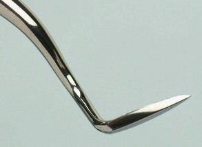
Figure 45-123 The two cutting edges of an interproximal knife are formed by bevels on the front and back surfaces of the blade.
As with the flat-bladed gingivectomy knives, only the bevels on the back surface of the interproximal knives need to be sharpened. Again, this can be accomplished by drawing the instrument across a stationary stone or by holding the instrument stationary and moving the stone across it.
Stationary Stone Technique
Stabilize a flat sharpening stone on a flat surface. Grasp the handle of the instrument with a modified pen grasp, and apply the bevel on the back surface of the blade to the flat surface of the sharpening stone. With moderate pressure, pull the instrument toward you (Figures 45-124 and 45-125). Release pressure slightly, and return to the starting point. Begin at one end of the cutting edge, and continue around the blade by rolling the handle of the instrument slightly between the thumb and the first and second fingers. Finish each section of the blade with a pull stroke to prevent formation of a wire edge. Check for sharpness as described previously.
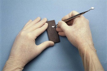
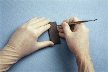
Stationary Instrument Technique
Grasp the instrument with the palm. Apply the flat surface of a handheld sharpening stone to the bevel on the back surface of the blade (Figure 45-126). Begin at one end of the cutting edge, and with moderate pressure, draw the stone back and forth across the instrument. To prevent the formation of a wire edge, finish each section with a stroke into or toward the cutting edge. Proceed around the entire length of the cutting edge by gradually rotating the instrument and the stone in relation to one another.
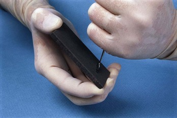
1 Adriaens P, Edwards C, DeBoever J, et al. Ultrastructural obsrevations on bacterial invasion in cementum and radicular dentin of periodontally diseased human teeth. J Periodontol. 1988;59:493.
2 Agger MS, Horsted-Bindslev P, Hovgaard O. Abrasiveness of an air-powder polishing system on root surfaces in vitro. Quintessence Int. 2001;32:407.
3 Aleo J, DeRenzis F, Farber P. In vitro attachment of human gingival fibroblasts to root surfaces. J Periodontol. 1975;46:639.
4 Aleo J, DeRenzis F, Farber P, et al. The presence and biological activity of cementum-bound endotoxin. J Periodontol. 1974;45:672.
5 Allen EF, Rhoads RH. Effects of high-speed periodontal instruments on tooth surfaces. J Periodontol. 1963;34:352.
6 Antonini CJ, Brady JM, Levin MP, et al. Scanning electron microscope study of scalers. J Periodontol. 1977;48:45.
7 Ashimoto A, Chen C, Bakker I, et al. Polymerase chain reaction detection of 8 putative periodontal pathogens in subgingival plaque of gingivitis and advanced periodontitis lesions. Oral Microbiol Immunol. 1996;11:266.
8 Axelsson P, Lindhe J. Effect of controlled oral hygiene procedures on caries and periodontal disease in adults: results after 6 years. J Clin Periodontol. 1981;8:239.
9 Baderstein A, Nilveus R, Egelberg J. Effect of nonsurgical periodontal therapy. I. Moderately advanced periodontitis. J Clin Periodontol. 1981;8:57.
10 Baderstein A, Nilveus R, Egelberg J. 4-year observations of basic periodontal therapy. J Clin Periodontol. 1987;14:438.
11 Baderstein A, Nilveus R, Egelberg J. Scores of plaque, bleeding, suppuration, and probing depth to predict probing attachment loss: 5 years of observation following nonsurgical periodontal therapy. J Clin Periodontol. 1990;17:102.
12 Baehni P, Thilo P, Chapuis B, et al. Effects of ultrasonic and sonic scalers on dental plaque microflora in vitro and in vivo. J Clin Periodontol. 1992;19:455.
13 Barnes C, Hayes E, Leinfelder K. Effects of an air abrasive polishing system on restored surfaces. Gen Dent. 1987;35:186.
14 Barnes JB, Harrel SK, Rivera-Hidalgo F. Blood contamination of the aerosols produced by in vivo use of ultrasonic scalers. J Periodontol. 1998;69:434.
15 Barnes JE, Schaffer EM. Subgingival root planing: a comparison using files, hoes, and curets. J Periodontol. 1960;31:300.
16 Basu MK, Browne RM, Potts AJ, et al. A survey of aerosol-related symptoms in dental hygienists. J Soc Occup Med. 1988;38:23.
17 Bay N, Overman P, Krust-Bray K, Cobb C, et al. Effectiveness of antimicrobial mouthrinses on aerosols produced by an air polisher. J Dent Hyg. 1993;67:312.
18 Becker W, Berg LE, Becker BE. Long-term evaluation of periodontal treatment and maintenance in 95 patients. Int J Periodont Restor Dent. 1984;4:54.
19 Berkstein S, Reiff RL, McKinney JF, et al. Supragingival root surface removal during maintenance procedures utilizing an air-powder abrasive system or hand scaling: an in vitro study. J Periodontol. 1987;58:327.
20 Bjornson EJ, Collins DE, Engler WO. Surface alteration of composite resins after curette, ultrasonic and sonic instrumentation: an in vitro study. Quintessence Int. 1990;21:381.
20a Brand HS, Entjes ML, Nieuw Amerongen AV, et al. Interference of electrical dental equipment with implantable cardioverter-defibrillators. Br Dent J. 2007;203(10):577-579.
21 Brookshire FV, Nagy WW, Dhuru VB, et al. The qualitative effects of various types of hygiene instrumentation on commercially pure titanium and titanium alloy implant abutments: an in vitro and scanning electron microscope study. J Prosthet Dent. 1997;78:286.
22 Burman LR, Alderman NE, Ewen SJ. Clinical application of ultrasonic vibrations for supragingival calculus and stain removal. J Dent Med. 1968;13:156.
23 Cadosch J, Zimmermann U, Ruppert M, et al. Root surface debridement and endotoxin removal. J Periodontal Res. 2003;38:229.
23a Calabrese N, Galgut P, Mordan N. Identification of Actinobacillus actinomycetemcomitans, Treponema denticola and Porphyromonas gingivalis within human dental calculus: a pilot investigation. J Int Acad Periodontol. 2007;9(4):118-128.
24 Canis MF, Kramer GM, Pameijer CM. Calculus attachment: review of the literature and findings. J Periodontol. 1979;50:406.
25 Checchi L, Pelliccioni GA. Hand versus ultrasonic instrumentation in the removal of endotoxin from root surface in vitro. J Periodontol. 1998;59:398.
26 Cheetham WA, Wilson M, Kieser JB. Root surface debridement: an in vitro assessment. J Clin Periodontol. 1988;15:228.
27 Chen SK, Vesley D, Brosseau LM, et al. Evaluation of single-use masks and respirators for protection of health care workers against mycobacterial aerosols. Am J Infect Control. 1994;22:65.
28 Claffey N. Decision making in periodontal therapy: the reevaluation. J Clin Periodontol. 1991;18:364.
29 Clark S, Group H, Mabler D. The effect of ultrasonic instrumentation on root surfaces. J Periodontol. 1968;39:125.
30 Contreras A, Slots J. Active cytomegalovirus infection in human periodontitis. Oral Microbiol Immunol. 1998;13:225.
31 Contreras A, Slots J. Herpesviruses in human periodontal disease. J Periodontal Res. 2000;35:3.
32 Contreras A, Slots J. Mammalian viruses in human periodontitis. Oral Microbiol Immunol. 1996;11:381.
33 Contreras A, Umeda M, Chen C, et al. Relationship between herpesviruses and adult periodontitis and periodontopathic bacteria. J Periodontol. 1999;70:478.
34 Council on Dental Materials, Instruments and Equipment, American Dental Association: Dental units and water retraction. J Am Dent Assoc. 1988;16:417.
35 Copulos TA, Low SB, Walker CB, et al. Comparative analysis between a modified ultrasonic tip and hand instruments on clinical parameters of periodontal disease. J Periodontol. 1993;64:694.
36 Cross-Poline GN, Shaklee RL, Stach DJ. Effect of implant curets on titanium implant surfaces. Am J Dent. 1997;10:41.
37 Cutler BJ, Goldstein GR, Simonelli G. The effect of dental prophylaxis instruments on the surface roughness of metals used for metal ceramic crowns. J Prosthet Dent. 1995;73:219.
38 Dragoo MR. A clinical evaluation of hand and ultrasonic instruments on subgingival debridement. Part I. With unmodified and modified ultrasonic inserts. Int J Periodontol. 1992;12:311.
39 Drisko CL. Scaling and root planing without overinstrumentation: hand versus power-driven scalers. Curr Opin Periodontol. 1993;3:78.
40 Drisko CL, Cochran DL, Blieden T, et al. Position paper: sonic and ultrasonic scalers in periodontics. Research, Science and Therapy Committee of the American Academy of Periodontology. J Periodontol. 2000;71:1792.
41 Eliades GC, Tzoutzas JG, Vougiouklakis GJ. Surface alterations on dental restorative materials subjected to an air-powder abrasive instrument. J Prosthet Dent. 1991;65:27.
42 Fitzgibbon EJ, Bartzokas CA, Martin MV, et al. The source, frequency and extent of bacterial contamination of dental unit water systems. Br Dent J. 1984;157:98.
43 Fox SC, Moriarty JD, Kusy RP. The effects of scaling a titanium implant surface with metal and plastic instruments: an in vitro study. J Periodontol. 1990;61:485.
44 Garnick JJ, Dent J. A scanning electron micrographical study of root surfaces and subgingival bacteria after hand scaling and ultrasonic instrumentation. J Periodontol. 1989;60:441.
45 Garrett JS. Effects of nonsurgical periodontal therapy on periodontitis in humans: a review. J Clin Periodontol. 1983;10:515.
46 Green E, Ramfjord SR. Tooth roughness after subgingival root planing. J Periodontol. 1966;37:396.
47 Green E, Seyer PC. Sharpening curets and sickle scalers, ed 2. Berkeley, Calif: Praxis; 1972.
48 Greenstein G. Nonsurgical periodontal therapy in 2000: a literature review. J Am Dent Assoc. 2000;131:1580.
49 Gross A, Devine MJ, Cutright DE. Microbial contamination of dental units and ultrasonic scalers. J Periodontol. 1976;47:670.
50 Gross KB, Overman PR, Cobb C, et al. Aerosol generation by two ultrasonic scalers and one sonic scaler. A comparative study. J Dent Hyg. 1992;66:314.
51 Haffajee AD, Socransky SS. Microbial etiological agents of destructive periodontal diseases. Periodontol 2000. 1994;5:78.
52 Hallmon WW, Waldrop TC, Meffert RM, et al. A comparative study of the effects of metallic, nonmetallic, and sonic instrumentation on titanium abutment surfaces. Int J Oral Maxillofac Implants. 1996;11:96.
53 Hannan MM, Azadian BS, Gazzard BG, et al. Hospital infection control in an era of HIV infection and multi-drug resistant tuberculosis. J Hosp Infect. 2000;44:5.
54 Harrel SK, Barnes JB, Rivera-Hidalgo F. Reduction of aerosols produced by ultrasonic scalers. J Periodontol. 1996;67:28.
54a Harrel SK, Barnes JB, Rivera-Hidalgo F. Aerosol reduction during air polishing. Quintessence Int. 1999;30(9):623-628.
55 Harrel SK, Barnes JB, Rivera-Hidalgo F. Aerosol and splatter contamination from the operative site during ultrasonic scaling. J Am Dent Assoc. 1998;129:1241.
56 Hatfield CG, Baumhammers A. Cytotoxic effects of periodontally involved surfaces of human teeth. Arch Oral Biol. 1971;16:465.
57 Holbrook T, Low S. Power-driven scaling and polishing instruments. Clin Dent. 1989;3:1.
58 Holbrook T, Low S. Power-driven scaling and polishing instruments. In: Hardin JF, editor. Clarke’s clinical dentistry. Philadelphia: Lippincott, 1991.
59 Holbrook WP, Muir KF, MacPhee IT, et al. Bacteriological investigation of the aerosol from ultrasonic scalers. Br Dent J. 1978;144:245.
60 Hughes FJ, Smales FC. Immunohistochemical investigation of the presence and distribution of cementum-associated lipopolysaccharides in periodontal disease. J Periodont Res. 1986;21:660.
61 Hughes FJ, Auger DW, Smales FC. Investigation of the distribution of cementum-associated lipopolysaccharides in periodontal disease with scanning electron microscope immunohistochemistry. J Periodontal Res. 1988;23:100.
62 Hughes TP, Caffesse RG. Gingival changes following scaling root planing and oral hygiene: a biometric evaluation. J Periodontol. 1978;49:245.
63 Johnson WN, Wilson JR. The application of the ultrasonic dental units to scaling procedures. J Periodontol. 1957;28:24.
64 Johnson WW, Barnes CM, Covey DA, et al. The effects of a commercial aluminum airpolishing powder on dental restorative materials. J Prosthodont. 2004;13:166.
65 Jokit W, editor. Zinsser’s microbiology, ed 20, Norwalk, Conn: Appleton & Lange, 1992.
66 Kaldahl WB, Kalkwarf KL, Patil KD, et al. Long-term evaluation of periodontal therapy. I. Response to 4 therapeutic modalities. J Periodontol. 1996;67:93.
67 Kerry GJ. Roughness of root surfaces after use of ultrasonic instruments and hand curets. J Periodontol. 1967;38:340.
68 Khatiblou FA, Ghodssi A. Root surface smoothness or roughness in periodontal treatment: a clinical study. J Peridontol. 1983;54:365.
69 Kocher T, Konig J, Hansen P, et al. Subgingival polishing compared to scaling with steel curettes: a clinical pilot study. J Clin Periodontol. 2001;28:194.
70 Kocher T, Langenbeck M, Ruhling A, et al. Subgingival polishing with a Teflon-coated sonic scaler insert in comparison to conventional instruments as assessed on extracted teeth. I. Residual deposits. J Clin Periodontol. 2000;27:243.
71 Koka S, Han J, Razzoog ME, et al. The effects of two air-powder abrasive prophylaxis systems on the surface of machined titanium: a pilot study. Implant Dent. 1992;1:259.
72 Kwan J, Zablotsky MH, Meffert RM. Implant maintenance using a modified ultrasonic instrument. J Dent Hyg. 1990;64:422.
73 Landry C, Long B, Singer D, et al. Comparison between a short and a conventional blade periodontal curet: an in vitro study. J Clin Periodontol. 1999;26:548.
74 Larato DC, Ruskin PF, Martin A. Effect of an ultrasonic scaler on bacterial counts in air. J Periodontol. 1967;38:550.
75 Lee SY, Lai YL, Morgano SM. Effects of ultrasonic scaling and periodontal curettage on surface roughness of porcelain. J Prosthet Dent. 1995;73:227.
76 Legnani P, Checchi L, Pelliccioni GA, et al. Atmospheric contamination during dental procedures. Quintessence Int. 1994;25:435.
77 Leknes KN, Lie T, Wikesjo UM, et al. Influence of tooth instrumentation roughness on subgingival microbial colonization. J Periodontol. 1994;65:303.
78 Leon LE, Vogel RI. A comparison of the effectiveness of hand scaling and ultrasonic debridement in furcations as evaluated by differential dark-field microscopy. J Periodontol. 1987;58:86.
79 Lever MS, Williams A, Bennett AM. Survival of mycobacterial species in aerosols generated from artificial saliva. Lett Appl Microbiol. 2000;31:238.
80 Lindhe J. Evaluation of periodontal scalers. II. Wear following standardized or diagonal cutting tests. Odontol Rev. 1966;17:121.
81 Lindhe J, Jacobson L. Evaluation of periodontal scalers. I. Wear following clinical use. Odontol Rev. 1966;17:1.
82 Lindhe J, Nyman S. Long-term maintenance of patients treated for advanced periodontal disease. J Clin Periodontol. 1984;11:504.
83 Lindhe J, Nyman S, Karring T. Scaling and root planing in shallow pockets. J Clin Periodontol. 1982;9:415.
84 Listgarten MA, Lindhe J, Hellden L. Effect of tetracycline and/or scaling on human periodontal disease: clinical microbiological and histological observations. J Clin Periodontol. 1978;5:246.
85 Lowenguth RA, Greenstein G. Clinical and microbiological response to nonsurgical mechanical periodontal therapy. Periodontol 2000. 1995;9:14.
86 Lubow RM, Cooley RL. Effect of air-powder abrasive instrument on restorative materials. J Prosthet Dent. 1986;55:462.
87 Magnusson I, Lindhe J, Yoneyama T, et al. Recolonization of a subgingival microbiota following scaling in deep pockets. J Clin Periodontol. 1984;11:193.
88 Mengel R, Buns CE, Mengel C, et al. An in vitro study of the treatment of implant surfaces with different instruments. Int J Oral Maxillofac Implants. 1998;13:91.
89 Michalowicz BS, Ronderos M, Camara-Silva R, et al. Human herpesviruses and Porphyromonas gingivalis are associated with juvenile periodontitis. J Periodontol. 2000;71:981.
90 Miller CS, Leonelli FM, Latham E. Selective interference with pacemaker activity by electrical dental devices. Oral Surg Oral Med Oral Pathol Oral Radiol Endod. 1998;85:33.
91 Miller RL. Characteristics of blood-containing aerosols generated by common powered dental instruments. Am Ind Hyg Assoc J. 1995;56:670.
92 Miller RL, Micik RE. Air pollution and its control in the dental office. Dent Clin North Am. 1978;22:453.
93 Miller RL, Micik RE, Abel C, et al. Studies on dental aerobiology. II. Microbial splatter discharged from the oral cavity of dental patients. J Dent Res. 1971;50:621.
93a Moëne R, Décaillet F, Andersen E, et al. Subgingival plaque removal using a new air-polishing device. J Periodontol. 2010;81(1):79-88.
94 Mongardini C, van Steenberghe D, Dekeyser C, et al. One stage full- versus partial-mouth disinfection in the treatment of chronic adult or generalized early-onset periodontitis. I. Long-term clinical observations. J Periodontol. 1999;70:632.
95 Moore J, Wilson M, Kieser JB. The distribution of bacterial lipopolysaccharide (endotoxin) in relation to periodontally involved root surfaces. J Clin Periodontol. 1986;13:748.
96 Moskow BS. Calculus attachment in cemental separations. J Periodontol. 1969;40:125.
97 Mousques T, Listgarten MA, Phillips RW. Effect of scaling and root planing on the composition of human subgingival microbial flora. J Periodontal Res. 1980;7:199.
98 Muir KF, Ross PW, MacPhee IT, et al. Reduction of microbial contamination from ultrasonic scalers. Br Dent J. 1978;145:760.
99 Nakib NM, Bissada NF, Simmelink JW, et al. Endotoxin penetration into root cementum of periodontally healthy and diseased human teeth. J Periodontol. 1982;53:368.
100 Nyman S, Westfelt E, Sarhed G, et al. Role of “diseased” root cementum in healing following treatment of periodontal disease: a clinical study. J Clin Periodontol. 1988;15:464.
101 Oberholzer R, Rateitschak KH. Root cleaning or root smoothing: an in vivo study. J Clin Periodontol. 1996;23:326.
102 O’Leary R, Sved AM, Davies EH, et al. The bactericidal effects of dental ultrasound on Actinobacillus actinomycetemcomitans and Porphyromonas gingivalis: an in vitro investigation. J Clin Periodontol. 1997;24:432.
103 Oosterwall PJ, Matee MI, Mikx FHM, et al. The effect of subgingival debridement with hand and ultrasonic instruments on subgingival microflora. J Clin Periodontol. 1987;14:528.
104 Oppenheim BA, Sefton AM, Gill ON, et al. Widespread Legionella pneumophila contamination of dental stations in a dental school without apparent human infection. Epidemiol Infect. 1987;99:159.
105 Orban B, Manella V. Macroscopic and microscopic study of instruments designed for root planing. J Periodontol. 1956;27:120.
106 Orton GS. Clinical use of an air-powder abrasive system. Dent Hyg. 1987;75:513.
107 Otero-Cagide FJ, Long BA. Comparative in vitro effectiveness of closed root debridement with fine instruments on specific areas of mandibular first molar furcations. I. Root trunk and furcation entrance. J Periodontol. 1997;68:1093.
108 Otero-Cagide FJ, Long BA. Comparative in vitro effectiveness of closed root debridement with fine instruments on specific areas of mandibular first molar furcations. I. Furcation area. J Periodontol. 1997;68:1098.
109 Pankhurst CL, Johnson NW, Woods RG. Microbial contamination of dental unit waterlines: the scientific argument. Int Dent J. 1998;48:359.
110 Paquette OE, Levin MP. The sharpening of scaling instruments. I. An examination of principles. J Periodontol. 1977;48:163.
111 Parr R, Green E, Madsen L, et al. Subgingival scaling and root planing. Berkeley, Calif: Praxis; 1976.
112 Pattison AM. The use of hand instruments in supportive periodontal treatment. Periodontol 2000. 1996;12:71.
113 Petersilka GJ, Bell M, Haberlein I, et al. In vitro evaluation of novel low abrasive air polishing powders. J Clin Periodontol. 2003;30:9.
114 Petersilka GJ, Bell M, Mehl A, et al. Root defects following air polishing. J Clin Periodontol. 2003;30:165.
115 Petersilka GJ, Flemmig TF, Mehl A, et al. Comparison of root substance removal by magnetostrictive and piezoelectric ultrasonic and sonic scalers in vitro. J Clin Periodontol. 1997;24:864.
116 Pihlstrom BL, McHugh RB, Oliphant TH, et al. Comparison of surgical and nonsurgical treatment of periodontal disease: a review of current studies and additional results after 6 years. J Clin Periodontol. 1983;10:524.
117 Proye M, Caton J, Polson A. Initial healing of periodontal pockets after a single episode of root planing monitored by controlled probing force. J Periodontol. 1982;53:296.
118 Quirynen M, Mongardini C, de Soete M, et al. The role of chlorhexidine in the one-stage full-mouth disinfection treatment of patients with advanced adult periodontitis: long-term clinical and microbiological observations. J Clin Periodontol. 2000;27:578.
119 Quirynen M, Mongardini C, Pauwels M, et al. One stage full- versus partial-mouth disinfection in the treatment of chronic adult or generalized early-onset periodontitis. II. Long-term impact on microbial load. J Periodontol. 1999;70:646.
120 Rajstein J, Tal M. The effects of ultrasonic scaling on the surface of Class V amalgam restorations: a scanning electron microscope study. J Oral Rehabil. 1984;11:299.
121 Rawson RD, Nelson BN, Jewell BD, et al. Alkalosis as a potential complication of air polishing systems: a pilot study. Dent Hyg. 1985;59:500.
122 Razzoog ME, Koka S. In vitro analysis of the effects of two air-abrasive prophylaxis systems and inlet air pressure on the surface of titanium abutment cylinders. J Prosthodont. 1994;3:103.
123 Renvert S, Wikström M, Dahlén G, et al. Effect of root debridement on the elimination of Actinobacillus actinomycetemcomitans and Bacteroides gingivalis from periodontal pockets. J Clin Periodontol. 1990;17:345.
124 Ritz L, Hefti AF, Rateitschak KH. An in vitro investigation on the loss of root substance in scaling with various instruments. J Clin Peridontol. 1991;18:643.
125 Rivera-Hidalgo F, Barnes JB, Harrel SK. Aerosol and splatter production by focused spray and standard ultrasonic inserts. J Periodontol. 1999;70:473.
126 Rosenberg ES, Evian CI, Listgarten M. The composition of the subgingival microbiota after periodontal therapy. J Periodontol. 1981;52:435.
127 Rossi R, Smukler H. A scanning electron microscope study comparing the effectiveness of different types of sharpening stones and curets. J Peridontol. 1995;66:956.
128 Ruhling A, Kocher T, Kreusch J, et al. Treatment of subgingival implant surfaces with Teflon-coated sonic and ultrasonic scaler tips and various implant curettes: an in vitro study. Clin Oral Implants Res. 1994;5:19.
129 Rutala WA, Jones SM, Worthington JM, et al. Efficacy of portable filtration units in reducing aerosolized particles in the size range of Mycobacterium tuberculosis. Infect Control Hosp Epidemiol. 1995;16:391.
130 Sbordone L, Ramaglia L, Guletta E, et al. Recolonization of the subgingival microflora after scaling and root planing in human periodontitis. J Periodontol. 1990;61:579.
131 Schaffer EM. Histologic results of root curettage on human teeth. J Periodontol. 1956;27:269.
132 Schenk G, Flemmig TF, Lob S, et al. Lack of antimicrobial effect on periodontopathic bacteria by ultrasonic and sonic scalers in vitro. J Clin Periodontol. 2000;27:116.
133 Schlageter L, Rateitschak-Pluss EM, Schwarz JP. Root surface smoothness or roughness following open debridement: an in vivo study. J Clin Periodontol. 1996;23:460.
134 Schwartz M. The prevention and management of the broken curet. Compend Contin Educ Dent. 1998;19:418.
135 Selvig KA. Attachment of plaque and calculus to tooth surfaces. J Periodontal Res. 1970;5:8.
136 Shiloah J, Patters M. Repopulation of periodontal pockets by microbial pathogens in the absence of supportive therapy. J Peridontol. 1996;67:130.
137 Shreve WB, Hoerman KC, Trautwein CA. Illness in patients following exposure to dental aerosols. J Public Health Dent. 1972;32:34.
138 Slots J, Mashimo P, Levine MJ, et al. Periodontal therapy in humans. I. Microbiological and clinical effects of a single course of periodontal scaling and root planing, and of adjunctive tetracycline therapy. J Periodontol. 1979;50:495.
139 Smart GJ, Wilson M, Davis EH, et al. The assessment of ultrasonic root surface debridement by determination of residual endotoxin levels. J Clin Periodontol. 1990;17:174.
140 Smith BA, Setter MS, Caffesse RG, et al. The effect of sharpening stones upon curette surface roughness. Quintessence Int. 1987;18:603.
141 Snyder JA, McVay JT, Brown FH, et al. The effect of air abrasive polishing on blood pH and electrolyte concentrations in healthy mongrel dogs. J Periodontol. 1990;64:81.
142 Stach DJ, Cross-Poline GN, Newmand SM, et al. Effect of repeated sterilization and ultrasonic cleaning on curet blades. J Dent Hyg. 1995;69:31.
143 Stahl SS, Slavkin HC, Yamada L, et al. Speculations about gingival repair. J Periodontol. 1972;43:395.
144 Stahl SS, Weiner JM, Benjamin S, et al. Soft tissue healing following curettage and root planing. J Periodontol. 1971;42:678.
145 Stambaugh RV. A clinician’s 3-year experience with perioscopy. Compend Contin Educ Dent. 2002;23(11A):1061-1070.
146 Stambaugh RV, Myers G, Stambaugh RV, et al. Endoscopic visualization of the submarginal gingiva dental sulcus and tooth root surfaces. J Periodontol. 2002;73(4):374-382.
147 Stende GW, Schaffer EM. A comparison of ultrasonic and hand scaling. J Periodontol. 1961;32:312.
148 Suzuki JB, Delisle AL. Pulmonary actinomycosis of periodontal origin. J Periodontol. 1984;55:581.
149 Tan B, Gillam DG, Mordan NJ, Galgut PN. A preliminary investigation into the ultrastructure of dental calculus and associated bacteria. J Clin Periodontol. 2004;31:364.
150 Ting M, Contreras A, Slots J. Herpesvirus in localized juvenile periodontitis. J Periodontal Res. 2000;35:17.
151 Torfason T, Kiger R, Selvig KA, et al. Clinical improvement of gingival conditions following ultrasonic versus hand instrumentation of periodontal pockets. J Clin Periodontol. 1979;6:165.
152 Trenter SC, Walmsley AD. Ultrasonic dental scaler: associated hazards. J Clin Periodontol. 2003;30:95.
153 Umeda M, Contreras A, Chen C, et al. The utility of whole saliva to detect the oral presence of periodontopathic bacteria. J Periodontol. 1998;69:828.
154 Van Volkinburg J, Green E, Armitage G. The nature of root surfaces after curette, cavitron, and alpha-sonic instrumentation. J Periodontal Res. 1976;11:374.
155 van Winkelhoff AJ, van der Velden U, de Graaff J. Microbial succession in recolonizing deep periodontal pockets after a single course of supra- and subgingival debridement. J Clin Periodontol. 1988;15:116.
156 Veksler AE, Kayrouz GA, Newman MG. Reduction of salivary bacteria by pre-procedural rinses with chlorhexidine 0.12%. J Periodontol. 1991;62:649.
157 Vermilyea SG, Prasanna MK, Agar JR. Effect of ultrasonic cleaning and air polishing on porcelain labial margin restorations. J Prosthet Dent. 1994;71:447.
158 Waerhaug J. Healing of the dentoepithelial junction following subgingival plaque control. J Periodontol. 1978;49:1.
159 Waerhaug J, Arno A, Lovdal A. The dimension of instruments for removal of subgingival calculus. J Periodontol. 1954;25:281.
160 Westfelt E, Nyman S, Socransky SS, et al. Significance of frequency of professional tooth cleaning following periodontal surgery. J Clin Periodontol. 1983;10:148.
161 Wilkins EM. Clinical practice of the dental hygienist, ed 10. Philadelphia: Lippincott, Williams & Wilkins; 2009.
162 Wilkinson RF, Maybury J. Scanning electron microscopy of the root surface following instrumentation. J Periodontol. 1973;44:559.
163 Wilson TG, Carnio J, Schenk R, et al. Absence of histologic signs of chronic inflammation following closed subgingival scaling and root planing using the dental endoscope: human biopsies—a pilot study. J Periodontol. 2008;79(11):2036-2041.
164 Wilson TG, Harrel SK, Nunn ME, et al. The relationship between the presence of tooth-borne subgingival deposits and inflammation found with a dental endoscope. J Periodontol. 2008;79(11):2029-2035.
165 Ximenez-Fyvie LA, Haffajee AD, Socransky SS. Comparison of the microbiota of supra- and subgingival plaque in health and periodontitis. J Clin Periodontol. 2000;27:648.
166 Zander HA. The attachment of calculus to root surfaces. J Periodontol. 1953;24:16.
167 Zappa U, Studer M, Merkle A, et al. Effect of electrically powered dental devices on cardiac parameter function in humans. Periodontology. 1991;2:299.