CHAPTER 29 Cone Beam Imaging for Endodontic Procedures
DALE A. MILES, THOMAS V. McCLAMMY
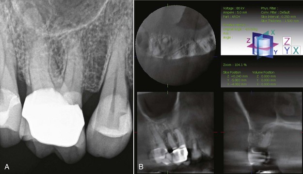
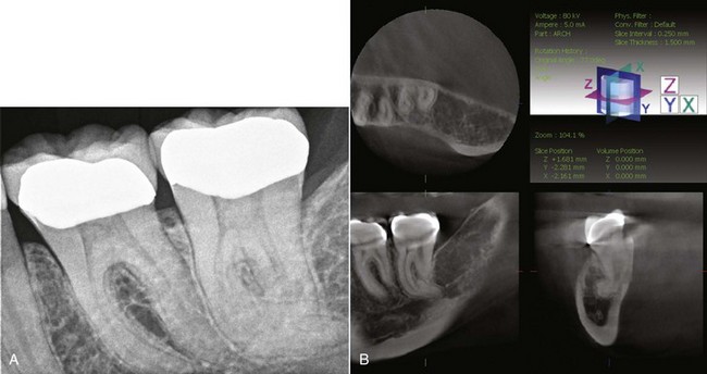
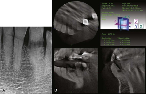
Although at first glance, it may seem that cone beam volumetric tomography (CBVT), also known as cone beam computed tomography (CBCT), may be “overkill” for diagnostic evaluation of endodontically compromised teeth, the interest and adoption of this advanced imaging modality is now becoming very popular with clinicians performing endodontic procedures—and for good reason. Two-dimensional (2D) grayscale images, whether they are conventional film or digital images, cannot accurately depict the full three-dimensional (3D) representation of the teeth and supporting structures. In fact, traditional images are very poor representations of even the pulpal anatomy. They grossly underestimate canal structure and often cannot accurately visualize periapical changes, especially where there is thick cortical bone, as in the presence of anatomic obstructions (Fig. 29-1, A).
On the other hand, CBVT allows the clinician to view the tooth and pulpal structures in thin slices in all three anatomic planes: axial, sagittal, and coronal. This capability alone allows visualization of periapical pathology and root morphology previously impossible (see Fig. 29-1, B).
Several tools available in CBVT, such as changing the vertical or horizontal angulation of the image “on the fly” or in real time, as well as thin-slice, grayscale data of 0.1 mm thickness, will never be available for conventional or even digital radiographic assessment.1 In addition, the ability to use CBVT data to view the region of interest in three anatomic planes of section at very low x-ray doses was never as easy or accessible as it is today. Most clinicians probably never even anticipated that such a precise imaging solution would be introduced to the dental profession during their careers.
This chapter will address the principles, applications, imaging attributes, image artifacts, and potential liability of adopting CBVT technology for endodontic procedures. Given this information, the student of endodontics will begin to realize the significant advantages and improved diagnostic and treatment-planning capabilities of this extraordinary radiographic imaging technology.
Principles of Cone Beam Volumetric Tomography
Three important parameters of cone-beam imaging are described in the following sections:
3.
Slice thickness/measurement accuracy
Voxels and Voxel Sizes
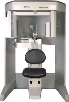
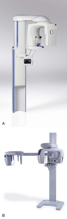
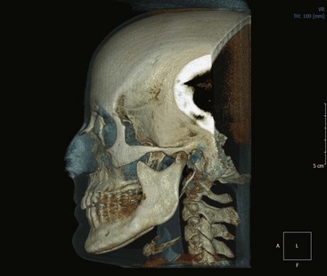
Unlike medical computed tomography (CT) scanning, cone-beam scanning machines acquire their x-ray information using low kV and low mA exposure parameters in a single pass from 180 to 360 degrees of rotation. Medical scanners use kilovoltages of 120 kV or more and milliamperages of about 400 mA. The highest exposure factors for any dental cone-beam scanner is the Imaging Sciences i-CAT (Imaging Sciences International, Hatfield, PA) (Fig. 29-2), which uses 120 kV and 24 mA. In contrast, dental scanners like the Planmeca Promax® (Planmeca Oy, Helsinki, Finland) (Fig. 29-3, A) or Veraviewepocs 3D (J. Morita Corporation, Kyoto, Japan) (Fig. 29-3, B) use typical dental exposure factors of about 5 to 7 mA and 70 to 80 kV. The x-ray dose for all cone-beam machines is significantly lower than the dose received from a medical computed axial tomography (CAT) scan.
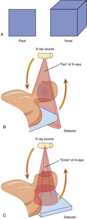
Besides lower exposure factors, the image data in cone-beam imaging is reconstructed from isometric voxels; that is, the images are constructed from pixels that are cubic and have the same dimensions for length, width, and depth. These voxel sizes are as small as 0.1 to 0.6 mm.1 By comparison, medical CAT scan slice data is 1 mm to 1 cm. Fig. 29-4 illustrates the difference between a pixel and a voxel, the difference between an anisometric pixel of medical CT and an isometric pixel (voxel) of CBVT, and how the pixel data is acquired from both modalities.
A patient in a medical CT scanner is moved in the scanner as little as 1 mm at a time as the image data is acquired. But for each slice acquired, the patient is exposed to ionizing radiation. If it takes 20 or 30 slices to acquire the data for the head region, the patient is exposed during the gathering of each slice. This results in significantly higher absorbed x-ray doses for the patient. A typical CBVT examination would expose the patient to only about 20 to 500 µSv in one rotation, whereas a typical medical examination of the head would approach 2100 µSv2 because the image data is gathered one section or layer at a time. Consequently, CBVT data has much higher resolution than medical CT data and is acquired at a fraction of the radiation dose. Because of the smaller voxel size, there is also greater image resolution.
Field of View
The FOV ranges from as small as a portion of a dental arch to an area as large as the entire head. Currently, the smallest FOV available is 37 × 50 mm (Fig. 29-5), which may be appropriate for a single arch. The largest, 220 × 220 mm (Fig. 29-6), is probably far larger than an endodontist would require, but many machines with larger FOVs can be collimated down to as little as 40 × 40 mm, making them very suitable for endodontic procedures. The selection of the FOV depends on several factors. Among the most important are:
3.
Spatial resolution requirements
4.
Clinician’s confidence interpreting the acquired data volume
Diagnostic Task
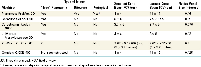
Since patients may have more than one tooth requiring an endodontic procedure, it may be desirable to have a machine capable of acquiring a CBVT volume greater than 40 × 40 mm. In addition, many clinicians may prefer more than one imaging modality to more fully evaluate their patients’ needs. There are several multifunctional cone beam machines available that will allow the clinician to acquire several image types with only one machine. Table 29-1 details the machines currently available that allow several types of images to be reconstructed from the data set. Fig. 29-7 illustrates the advantages of using multiple image types for an endodontic case.
Type of Patient
Just because you own a cone beam machine does NOT mean that every patient will require a cone-beam scan.2 More importantly, some patients requiring an endodontic procedure may be children or adolescents in whom the need to minimize the absorbed x-ray dose is more critical. Cone-beam machines with smaller FOVs can somewhat limit the radiation dose to critical organs and tissues of the head and neck in these cases.
Spatial Resolution Requirements
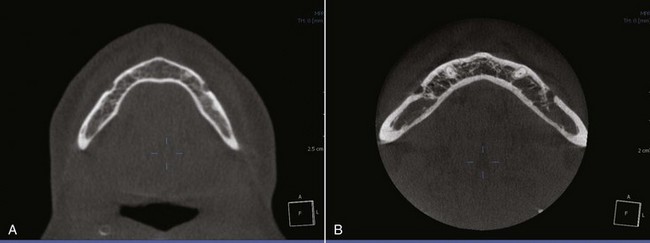
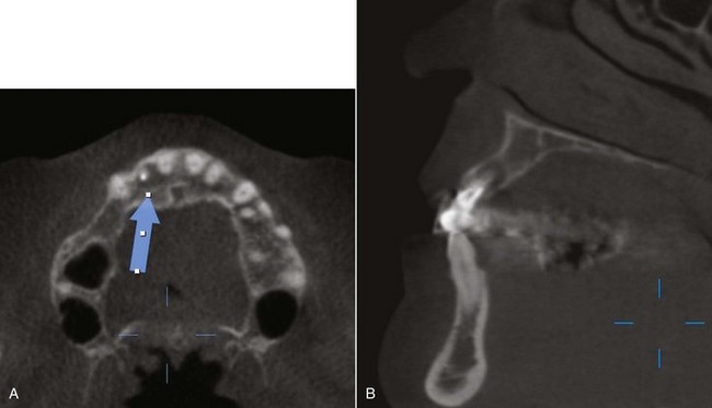
All endodontic imaging procedures require high spatial resolution. Assessment of canal structure, canal length, and lesions of endodontic origin (LEOs)3 exhibiting apical change are all important tasks requiring minute detail. If CBVT is employed, the data acquisition should be performed at the smallest voxel size. The smaller the voxel size, the higher the spatial resolution. Many of the larger stand-alone cone-beam machines, such as the Imaging Sciences i-CAT, set their voxel size defaults to 0.4 mm. This voxel size is inadequate for high spatial detail. However, these same machines often have a voxel size selection program that allows smaller voxel size during the image acquisition. The absolute minimum voxel size for endodontic imaging should be 0.2 mm. Machines such as those cited in Table 29-1 typically use voxel sizes of 0.076 to 0.16 mm for their native image capture. Fig. 29-8 shows two images taken at the axial slice level of the mental foramen. Fig. 29-8, A shows a slice using a voxel size during capture of 0.4 mm. Fig. 29-8, B shows an axial slice at the same level using a voxel size of 0.16 mm.
Clinician’s Confidence Interpreting the Acquired Data Volume
As previously stated, endodontic imaging procedures can be appropriately performed with small volume data sets. Unless there are multiple teeth in different quadrants requiring endodontic diagnostics or procedures, a small FOV is probably sufficient. This also reduces the diagnostic responsibility for occult pathology outside the region of interest (ROI). Large-FOV machines will capture structures like the paranasal sinuses, airway, and vertebral column, so the clinician has an ethical and legal responsibility to examine these structures for potential pathoses.4,5 To ignore these non-odontogenic regions would be considered negligence. Clinicians have the option to perform the radiographic evaluation themselves or refer the data volume to a qualified specialist such as an oral and maxillofacial radiologist or medical radiologist.5,6
For endodontists, and indeed most general clinicians, a CBVT scanner with a smaller FOV may be more appropriate.
Imaging Tasks Improved or Simplified by Cone Beam Volumetric Tomography
For endodontic treatment and assessments, there are at least five primary imaging tasks whereby CBVT scans have a distinct advantage over traditional 2D radiographs. These include evaluation of the following:
1.
Apical morphology and suspected lesions of endodontic origin
2.
Root canal system morphology
3.
Presurgical visualization
4.
Suspected root fractures and trauma
5.
Internal and external root resorption
Apical Morphology and Suspected Lesions of Endodontic Origin
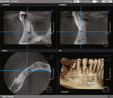
The precise location and visualization of root morphology is vastly improved with cone-beam data. Root curvature, root path, and anomalies within the canals themselves (e.g., obstructions, narrowing, bifurcation) are made more apparent when all three anatomic planes of section are available for review, especially with the capability of narrowing the slice thickness to as little as 0.1 mm (Fig. 29-9). Visual obstruction from anatomic features such as buccal bone and the malar process over the apices of maxillary roots simply “disappear” when you can scroll through the slices of the bone from facial to palatal in 0.1-mm sections while also changing axial orientations.
Additional benefits of some CBVT imaging software include allowing the clinician to create a pseudopanoramic image—that is, a thin-slice grayscale image of the mandible, maxilla, or both. Conventional panoramic machines, though not commonly employed by endodontists, use the mandible to select the focal trough, or zone of sharpness. This means that the palatal roots of the maxillary posterior teeth may not be centered in the focal trough. With CBVT imaging software, a central plane through the maxilla or mandible can be drawn so that the structures of interest can always be centered. This facilitates apical lesion assessment, even with a panoramic image (Fig. 29-10).
Radiographically, it is fundamental to understand that lesions of endodontic origin arise secondary to pulpal breakdown products and form adjacent to canal portals of exit.7,8 These lesions can and do form three-dimensionally anywhere along root surface anatomy.9 Prior to CBVT, clinicians were unable to visualize the specific location and extensiveness of periapical bone loss.
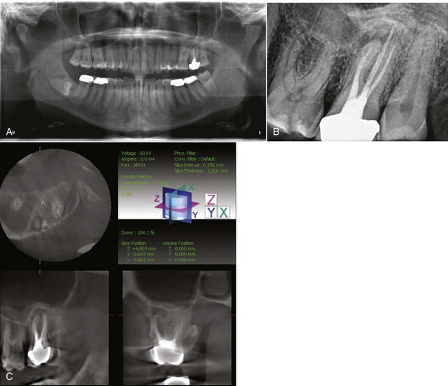
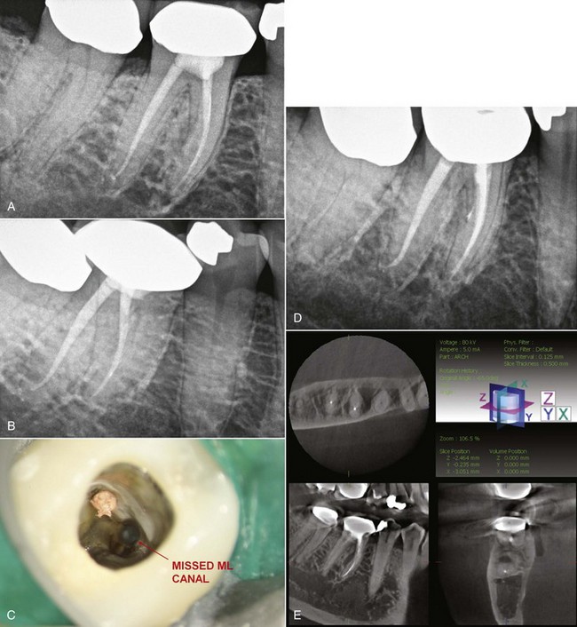
Fig. 29-11, A is a 2D periapical radiograph of the previous endodontic treatment of tooth #30, revealing no objective radiographic pathosis. The patient reported that tooth # 30 had been treated by an endodontist 5 years ago. The patient had returned to the treating clinician numerous times over the last 5 years complaining of tooth pain in this area. The patient was last advised that the area “had not enough time to heal.” However, an additional radiograph exposed with a different angulation revealed that only one of the two mesial canals were cleaned and obturated (Fig. 29-11, B). Using available CBVT technology, additional radiographs would not be necessary to elucidate this information (Fig. 29-11, C-D).
Fig. 29-11, E shows multiplanar views of tooth #30 taken with a contemporary CBVT machine. This image set reveals:
1.
A very high probability of a missed ML canal
2.
A lesion of endodontic origin developing on the mid-furcation side of the mesial root (large white arrows)
3.
Early periapical and periradicular changes of tooth # 31 (small white arrow)
Tooth #30 was sensitive to percussion and buccal alveolar bone palpation. While it can be concluded from the information available for the CBVT image that tooth #30 is the source of the patients’ pain, the clinician can also inform the patient that tooth #31 may also need endodontic therapy and that a further evaluation of this tooth is necessary.
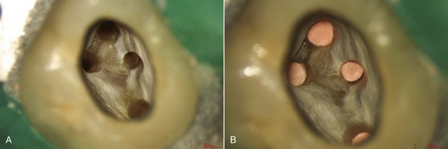
Root Canal System Morphology
As the adage goes, nature seldom makes a straight line and never makes two of the same. This statement is dramatically illustrated when evaluating root canal system morphology. With ever-present unusual and atypical root shapes and numbers, there is a need to look further than what a clinician can see or imagine with 2D radiography (Fig. 29-12).
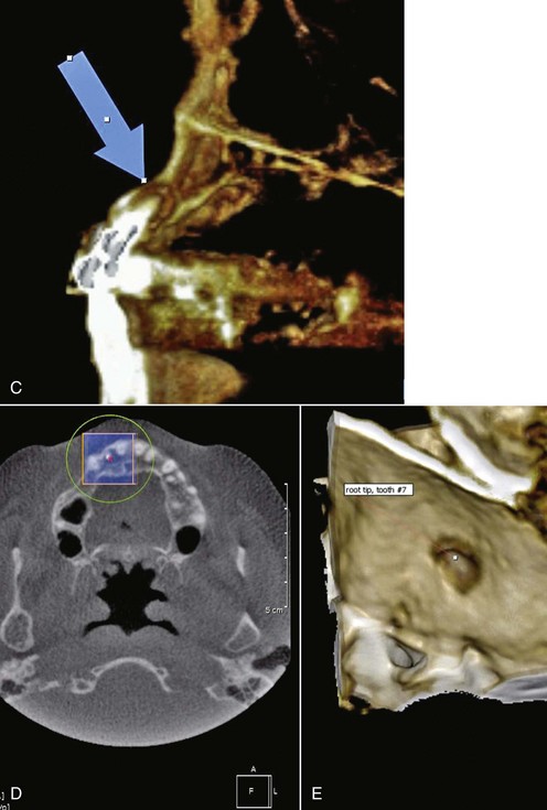
Presurgical Visualization
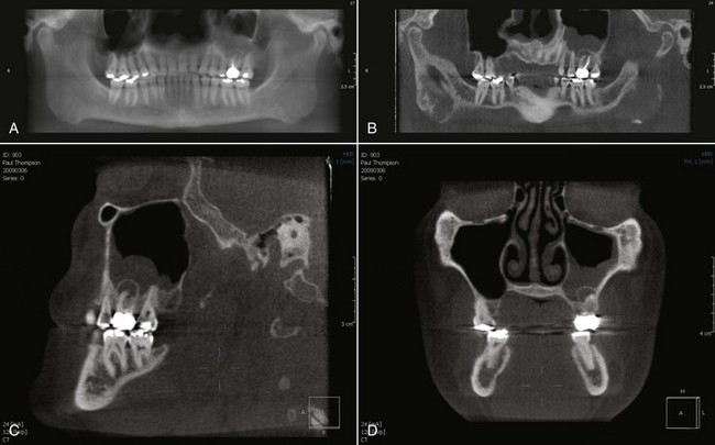
Surgical endodontic treatment is often performed in cases of endodontic nonhealing when nonsurgical retreatment is not possible. In the past, conventional and digital 2D periapical radiographs have been the only way to assess the apical region. Unfortunately, the information available from these images may not adequately prepare the clinician to surgically resolve the pathosis. For example, the clinician may be unable to observe whether the lesion has perforated the buccal and/or palatal cortical plates, as in the example that follows, or even observe which root or roots are involved. Presurgical confusion is resolved with cone-beam imaging. Multiplanar views allow the clinician to see the defect and suspected causes from the axial, sagittal, and coronal aspects; 3D grayscale or color imaging helps to visualize the entire defect before the incision is created. This is an immense improvement over conventional imaging (Fig. 29-13).
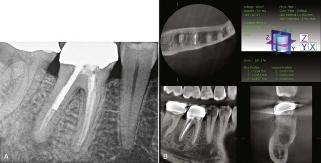
Suspected Root Fractures and Trauma
Fig. 29-14 shows 2D and 3D images of the endodontic and restorative treatment of tooth #30. The 2D periapical radiograph illustrates incomplete distal canal obturation, with associated periapical bone loss in the area of the apical third of the distal root. The CBVT image reveals a horizontal root fracture in the distal root at the apical extent of the post. Without this valuable information, the clinician may have attempted nonsurgical retreatment or an apicoectomy. Instead the patient can be informed of a hopeless prognosis, and valuable treatment time, expenses, and patient and clinician frustration can be avoided because of the enhanced information provided from the CBVT imaging.
Internal and External Root Resorption
Most clinicians are aware—and ideally communicate to their patients—that the long-term prognosis for teeth with extensive root resorption may be unpredictable. Endodontic treatment can often resolve these defects, with early diagnosis and treatment typically providing an improved prognosis. CBVT imaging of these resorption lesions provides the clinician with enhanced information so that more appropriate treatment-planning options are available (Fig. 29-15).
References
1. Miles DA. Color atlas of cone beam volumetric imaging for dental applications. Hanover Park, IL: Quintessence Publishing; 2008.
2. Miles DA, Danforth RA A clinician’s guide to understanding cone beam volumetric imaging Academy of Dental Therapeutics and Stomatology, Special Issue, pp 1–13 www.ineedce.com, 2007
3. Schilder H. Cleaning and shaping the root canal system. Dent Clin North Am. 1974;18:269-296.
4. Miles DA. Interpreting the cone beam data volume for occult pathology. Semin Orthod. 2009;15:70-76.
5. Miles DA. The agony and the ecstasy of cone beam technology. Part II: The agony. J Implant Adv Clin Dent. 2009;1:45-55.
6. Friedland B. Medicolegal issues related to cone beam CT. Semin Orthod. 2009;15(1):77-84.
7. Ruddle CJ. Endodontic disinfection-tsunami irrigation. Endod Prac. 2008:Feb 7-15.
8. Schilder H. Canal debridement and disinfection. In: Cohen S, Burns C, editors. Pathways of the pulp. 1st ed. St. Louis: Mosby; 1976:111-133.
9. Ruddle CJ. Endodontic diagnosis. Dent Today. 2002;21(10):90-92, 94, 96101.
10. Carr GB, McClammy TV: TDO Scientific Session 2009 Lecture Series.