CHAPTER 22 Repairs and Additions to Removable Partial Dentures
The need for repairing or adding to a removable partial denture will occasionally arise. However, the frequency of this occurrence should be held to a minimum by careful diagnosis, intelligent treatment planning, adequate mouth preparations, and the carrying out of an effective removable partial denture design with proper fabrication of all component parts. Any need for repairs or additions will then be the result of unforeseen complications that arise in abutment or other teeth in the arch, breakage or distortion of the denture through accident, or careless handling by the patient, rather than faulty design or fabrication.
It is important that the patient is instructed in proper placement and removal of the prosthesis so that undue strain is not placed on clasp arms, on other parts of the denture, or on contacted abutment teeth. The patient also should be advised that care must be given to the prosthesis when it is out of the mouth, and that any distortion may be irreparable. It should be made clear that there can be no guarantee against breakage or distortion from causes other than obvious structural defects.
Broken Clasp Arms
The following are several reasons for breakage of clasp arms:
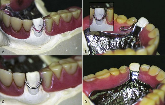
Figure 22-1 Fractured direct retainer on canine abutment. The reason for breakage is likely the long-term repeated flexure from movement associated with this 8-year-old distal extension prosthesis. The denture must be evaluated for prospective serviceability if the retainer arm is repaired. Often, the patient will best be served by replacing the denture with a new restoration. A, The cast produced from an irreversible hydrocolloid pick-up impression. The height of contour is shown in pencil, with a red line illustrating to the laboratory the location of repair wire (18-gauge). B, Clasp adapted to the designated line on the canine and fitted into the resin trough distal to the canine and palatal to the first and second premolars. Note the curvature placed at the end of the wire to prevent movement within the polymerized resin. C, Finished and polished wire repair from the buccal. D, Palatal view.
Fractured Occlusal Rests
Breakage of an occlusal rest almost always occurs where it crosses the marginal ridge. Improperly prepared occlusal rest seats are the usual cause of such weakness: an occlusal rest that crosses a marginal ridge that was not lowered sufficiently during mouth preparations may be made too thin or may be thinned by adjustment in the mouth to prevent occlusal interference. Failure of an occlusal rest rarely results from a structural defect in the metal and rarely if ever is caused by accidental distortion. Therefore the blame for such failure must often be assumed by the dentist for not having provided sufficient space for the rest during mouth preparations.
Soldering may repair broken occlusal rests. In preparation for the repair, it may be necessary to alter the rest seat of the broken rest or to relieve occlusal interferences. With the removable partial denture in its terminal position, an impression is made in irreversible hydrocolloid and then is removed, with the removable partial denture remaining in the impression. The dental stone is poured into the impression and is allowed to set. The removable partial denture is removed from the cast, and platinum foil is adapted to the rest seat and the marginal ridge and overlaps the guiding plane. The removable partial denture is returned to the cast and, with a fluoride flux, gold solder is electrically fused to the platinum foil and the minor connector in sufficient bulk to form an occlusal rest. An alternative solder to use is an industrial brazing alloy, which is higher fusing but responds excellently to electric soldering and does not tarnish.
Distortion or Breakage of Other Components—Major and Minor Connectors
Assuming that major and minor connectors were originally made with adequate bulk, distortion usually occurs from abuse by the patient (Figure 22-2). All such components should be designed and fabricated with sufficient bulk to ensure their rigidity and permanence of form under normal circumstances.
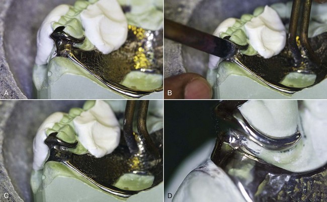
Figure 22-2 A, The maxillary juncture between major and minor connectors at the distalmost posterior molar has fractured. Thin platinum foil has been adapted to the cast beneath the fracture, the clasp assembly has been stabilized on the cast with fast-set plaster, the remainder of the prosthesis has been positioned on the cast in full contact with teeth and tissues, and the solder has been positioned for the electric tip to be placed. B, The electric soldering tip and ground are in place. C, Immediately following solder flow, the fracture has been eliminated by the solder connecting the two segments. D, The polished solder repair is ready to be cleaned and returned to the patient. The patient is told that this repair is not as strong as the original, and although it is difficult to know how long it could serve the patient, careful handling of the prosthesis is mandatory.
Major and minor connectors occasionally become weakened by adjustment to prevent or eliminate tissue impingement. Such adjustment at the time of initial placement may result from inadequate survey of the master cast or from faulty design or fabrication of the casting. This is inexcusable and reflects on the dentist. Such a restoration should be remade instead of further weakening the restoration by attempting to compensate for its inadequacies by relieving the metal. Similarly, tissue impingement that arises from inadequately relieved components results from faulty planning, and the casting should be remade with enough relief to prevent impingement. Failure of any component that was weakened by adjustment at the time of initial placement is the responsibility of the dentist. However, adjustment made necessary by settling of the restoration because abutment teeth have become intruded under functional loading may be unavoidable. Subsequent failure that results from the weakening effect of such an adjustment may necessitate making a new restoration as a consequence of tissue changes. Commonly, repeated adjustment to a major or minor connector results in loss of rigidity to the point that the connector can no longer function effectively. In such situations, a new restoration must be made, or that part must be replaced by casting a new section and then reassembling the denture by soldering. This occasionally requires disassembly of denture bases and artificial teeth. The cost and probable success must then be weighed against the cost of a new restoration. Generally the new restoration is advisable.
Loss of a Tooth or Teeth not Involved in Support or Retention of the Restoration
Additions to a removable partial denture are usually simply made when the bases are made of resin (Figure 22-3). The addition of teeth to metal bases is more complex and necessitates casting a new component and attaching it by soldering or creating retentive elements for the attachment of a resin extension. In most instances when a distal extension denture base is extended, the need should be considered for subsequent relining of the entire base. After the denture base has been extended, a relining procedure for both the new and the old base should be carried out to provide optimum tissue support for the restoration.
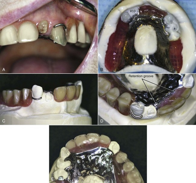
Figure 22-3 This patient presented with an asymptomatic fractured lateral incisor. A, Clinical presentation of the fractured tooth and prosthesis. Evaluation of the prosthesis revealed it to be adequately fitting, stable, and retentive. B, Pick-up impression of the prosthesis. C, Cast formed from the pick-up impression, showing a fully seated prosthesis. D, Preparation of the prosthesis included a mechanical means for retention (which was provided by creating a recess in the resin adjacent to the missing tooth) and creating a trough at the external finishing line to repair an area of marginal breakdown. E, The finished repair, which will be taken to the mouth and checked for occlusal clearance lingual to the maxillary anterior teeth.
Loss of an Abutment Tooth Necessitating its Replacement and Making a New Direct Retainer
In the event of a lost abutment, the next adjacent tooth is usually selected as a retaining abutment, and it generally will require modification or a restoration. Any new restoration should be made to conform to the original path of placement, with proximal guiding plane, rest seat, and suitable retentive area. Otherwise, modifications to the existing tooth should be done the same as during any other mouth preparations, with proximal recontouring, preparation of an adequate occlusal rest seat, and any reduction in tooth contours necessary to accommodate retentive and stabilizing components. A new clasp assembly may be cast for this tooth and the denture reassembled with the new replacement tooth added.
Other Types of Repairs
Other types of repairs may include the replacement of a broken or lost prosthetic tooth, the repair of a broken resin base, or the reattachment of a loosened resin base to the metal framework. Breakage is sometimes the result of poor design, faulty fabrication, or use of the wrong material for a given situation. Other times, it results from an accident that will not necessarily repeat itself. If the latter occurs, repair or replacement usually suffices. On the other hand, if fracture has occurred because of structural defects, or if it occurs a second time after the denture has been repaired once before, then some change in the design—by modification of the original denture or with a new denture—may be necessary.
Repair by Soldering
Approximately 80% of all soldering in dentistry can be done electrically. Electric soldering units are available for this purpose, and most dental laboratories are so equipped. Electric soldering permits soldering close to a resin base without removing that base because of rapid localization of heat at the electrode. The resin base needs only to be protected with a wet casting ring liner during soldering.
Color-matching gold solder may be used for soldering both gold and chromium-cobalt alloys. A solder for gold alloys that melts at between 1420°F and 1500°F is entirely adequate for soldering gold alloys to chromium-cobalt alloys, thereby lessening the chance of recrystallizing gold wrought wire via excessive and prolonged heat. For electric soldering, triple-thick solder should be used so the additional bulk of the solder will retard melting momentarily, while the carbon electrode conducts heat to the area to be soldered. For soldering chromium-cobalt alloys, a color-matching white 19K gold solder—which melts at about 1676°F—is used. An application of flux is essential for the success of any soldering operation to prevent oxidation of the parts to be joined and the solder itself. A borax-type flux is used when gold alloys are soldered. Fluoride-type flux must be used when chromium-cobalt alloys are soldered. When a gold alloy is to be soldered to a chromium-cobalt alloy, a fluoride-type flux should be chosen.
The following is a procedure for electric soldering:
Torch soldering requires an entirely different approach. It is used when the solder joint is long or unusually bulky, and when a larger quantity of solder has to be used. Torch soldering cannot be undertaken to repair a removable partial denture framework that has resin denture bases or artificial teeth supported by resin. The procedure for torch soldering is as follows: