Chapter 8 The X-ray tube
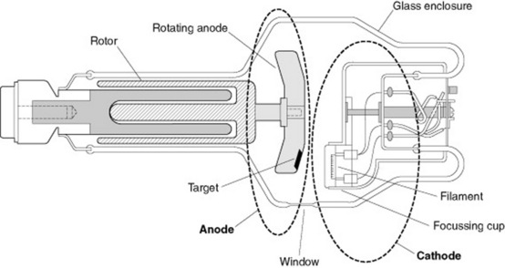
 The electrons are accelerated across a potential difference ranging from 40 to 120 kV in a diagnostic X-ray tube. X-rays are produced as bremsstrahlung and characteristic radiation at the anode with an efficiency of around 1%. The anode is rotated by an induction motor with coils outside the glass envelope and a copper rotor inside attached to the anode. X-rays are produced at the focal spot on the anode, the smaller the focal spot the smaller the penumbra of the X-ray beam. X-rays are emitted in all directions from the tube but are constrained to a small area by a ‘window’ or port in the tube housing.
INTRODUCTION
Since the discovery of X-rays in 1895 by Roentgen and the heated cathode X-ray tube by Coolidge, X-ray tubes have developed into complex pieces of electromechanical engineering. They comprise around 350 parts, taking 150 assembly operations. The cost (at date of publication) can be as much as £20 000.
The production of X-rays for diagnostic imaging requires fast moving electrons to be rapidly decelerated; the design and function of the major components to facilitate this will be discussed.
The key components of a modern rotating anode X-ray tube (Fig. 8.1) are:
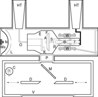
Figure 8.1 Rotating anode X-ray tube. A Anode disk, B Ball bearings, C Collimator lamp, D Collimator diaphragm, E Glass envelope, F Focal track, HT High-tension cable socket, K Cathode assembly, L Lead lining, M Mirror, Ms Microswitch, N Expansion diaphragm, O Oil, P Tube port, R Rotor assembly, S Anode stem, T Rotor support, V Plastic window, W Stator windings.
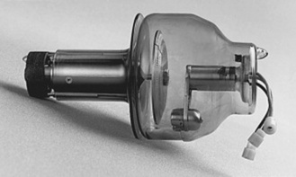
TUBE HOUSING
The tube housing protects the delicate insert from damage during use (Fig. 8.2). It is made of steel or aluminium with an external protective coat of paint to allow easy cleaning and an internal lining of lead to reduce radiation leakage to below the required maximum. The cover has special mounting rings, trunions for attachment to the tube suspension equipment, and sealed terminals and sockets for the high-tension cables and other associated control equipment connections. On the external surface the tube is marked to indicate the position of the focus point of the anode and a plate indicates the electrical characteristics and date of manufacture.
The cover is lined with lead to reduce radiation leakage, except for the X-ray port, which is made of plastic or beryllium. Beryllium is used as it has low X-ray absorption due to its proton number of 4.
Legislation varies in different countries; however, a typical figure for the maximum radiation leakage from an X-ray tube housing at 1 meter distance from the tube, with collimators closed, is 1 mGy per hour when the tube is operating at its maximum factors.
The tube housing is earthed to provide shock proofing and contains mineral oil surrounding the insert to electrically insulate it and aid cooling. Expansion bellows within the tube housing allows expansion of the oil when the X-ray tube heats up during use.
VACUUM ENVELOPE
In order for the X-ray tube to operate, the anode and cathode need to be contained in a vacuum;this vacuum is contained within the tube envelope. The envelope needs to be strong enough to support the anode and cathode assemblies, provide electrical insulation between the two and maintain the vacuum. The tube vacuum envelope is generally made of glass although some high-power tube envelopes are made of metal or ceramic.
Glass tube envelopes are made of borosilicate glass, which provides the required strength, low coefficient of thermal expansion and electrical insulation. Metal and combined metal with ceramic insulation are alternative methods of construction with the advantages of greater strength and mechanical stability compared to previous tubes made of glass; heat dissipation is also improved.
The X-ray window is a portion of the tube envelope which is thinner than the rest of the structure to allow X-ray output from the tube, minimising radiation absorption.
The wire penetrating the glass seals at the end of the tube is known as Dumet wire, a copper-coated alloy of nickel and iron that has the same coefficient of expansion as the glass.
FILAMENT ASSEMBLY
The filament is the source of electrons used in the production of X-rays. Electron production occurs when the filament is heated to around 2000 °C, this is achieved by passing a current through the filament. The temperature of the filament determines the number of electrons produced and is controlled by the milliamperes (mA) selected by the operator. The filament assembly is constructed as an electromagnetic lens so that it focusses the accelerated electrons to a small area of the anode – the focal spot.
There are usually two filaments: a small one with low output for better geometric resolution and a larger filament for higher output capacity, with wire diameters of 0.22 mm and 0.3 mm diameter, respectively. The filament is constructed as a spiral, with dimensions calculated to maximise the even density of the electrons produced. An alternative electron source is the flat emitter filament instead of a helix. This is used for some modern mammography tubes and allows a better X-ray intensity distribution than with the helix, thus improving image quality.
The filament is generally made of tungsten as it is:
Tungsten’s low coefficient of linear thermal expansion ensures the dimensions change little when it is heated, and the low vapour pressure ensures little tungsten is vaporised. This is important because, when deposited on the inside of the glass tube, tungsten reduces output and increases the possibility of arcing, causing severe damage to the tube. The addition of between 1% and 2% thorium to the tungsten improves thermionic emission.
FILAMENT WIRE ARRANGEMENTS
The filaments are mounted in a focussing cup, the purpose of which is to focus the electrons produced by the filament onto the focal spot of the anode. This is achieved using electrostatic focussing.
The arrangement of the two helixes depends on the tube type and different manufacturers’ tubes vary as well in the form of their focussing cup. There are general differences, which are sometimes expressed in the tube names. Siemens, for example, have Pantix tubes where both filaments are mounted parallel, or there is just one single filament; Biangulix, where both filaments are in-line; and finally a specialist tube, Megalix, with either two parallel helixes or with three – two in-line and the third parallel. In tubes with two parallel filaments both electron beams are focussed on the same area of the anode; where the filaments are in-line they are focussed on different areas of the anode.
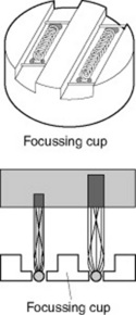
THE FOCUSSING CUP
The filament is set centrally in a slot machined into a metal focussing cup: the cathode cup.The shape of the cup, along with the electrostatic forces, prevents the electron beam fanning out, concentrating it on the focal spot of the anode (Fig. 8.3).
This design is called an electronic lens system with a resulting focal spot width that depends upon:
Cathode cups are typically manufactured from molybdenum, nickel or an iron alloy to ensure dimensional stability during use when the assembly becomes hot.
A separate filament transformer in the high-tension tank separates the primary low voltage side from the secondary high tension (HT) side of the transformer. The HT is connected to a common lead for both filaments and the focussing cup. Both filaments and focussing cup make-up the cathode and have negative polarity.
When the X-ray set is turned on the filament is supplied with a lower than operating current to heat the filament and prepare it for the higher current needed during exposure. This produces a cloud of electrons around the filament. The electrostatic field limits the number of electrons produced at the filament, thereby limiting the maximum tube current possible; this is called the ‘space charge effect’. As the tube voltage increases, the tube current increases up to a point when all the electrons in the space charge have been used up and the tube is then said to have reached saturation current.
GRID-CONTROLLED X-RAY TUBES
Specialised X-ray tubes used in capacitor discharge mobiles, cine radiography and some angiography units, where there is a need to provide rapid switching, utilise grid control of the exposure.
Normally, the focussing cup is kept at the same negative potential as the filament. In a grid-controlled tube the focussing cup may be negatively charged in comparison to the filament and so the voltage is large enough to prevent the flow of electrons from the filament to the anode. The voltage applied between the focussing cup and filament acts as a switch to turn the tube current on and off. This is known as secondary switching, as opposed to the primary switching.
THE ANODE
Original X-ray tubes were designed with a tungsten anode set in a block of copper. The tungsten produces the X-rays and the copper carries the heat away from the tungsten. This design limits the X-ray output as the rise in temperature would eventually lead to melting of the tungsten. Stationary anode designs are still used in low-output applications, such as dental radiography, as they are simpler to construct, robust and cheaper.
In 1929 Bouwers at Phillips produced the first commercial rotating anode tube, known as the Rotalix. Here the anode was a rotating disc where the area bombarded by the filament electrons – the focal spot – became a focal track with a much larger surface area and volume and with a correspondingly larger heat capacity.
The anode is the positive terminal of the X-ray tube; it serves to conduct the tube current, provide support of the target and provides a means ofdissipating the heat away from the target. X-rays are produced by the rapid deceleration of fast moving electrons and tungsten is used as the material of choice for the combination of its properties.
Properties of tungsten
These stationary anodes are found in basic X-ray tubes with low power requirements such as those in dental equipment, mobile C-arm units for fluoroscopy and low-load radiography. The low power requirements of these applications results in much lower heat generation and these requirements can be met using a stationary anode tube.
STATIONARY ANODE
The stationary anode tube has a compound anode, which consists of a tungsten target set in a block of copper, the X-rays are produced in the tungsten and the copper conducts the heat away from the target (Fig. 8.4A).
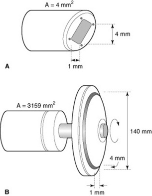
The anode block consists of a solid copper rod expanded at one end with an inclined target face end, the angle of inclination determines the focal spot size.
In a stationary anode the X-rays are produced in a small area of the anode (approx. 4 mm2) (Fig. 8.4B), which causes the temperature to rise rapidly; this limits the loading available before damage occurs.
ROTATING ANODE
The rotating anode X-ray tube is a design improvement to allow greater tube loading (Fig. 8.5). The anode is formed as a disc mounted on a rotating stem with the rotational power provided by an induction motor system.
The anode disc is between 55 mm and 100 mm in diameter and 7 mm thick, machined to high tolerance to prevent imbalance and wobble. The disc will experience rotational speeds up to 10 000 rpm and temperatures of 2000 °C. The disc has a tungsten–rhenium target area. The addition of a small quantity (5–10%) of rhenium prevents crazing of the anode surface.
In a rotating anode the target is formed as a track near the perimeter of a rotating disc. With a typical anode disc diameter of 9 cm, the target track area is approximately 1200 mm2. If the exposure time is long enough and the speed of rotation of the anode disc fast enough, the heating effect is spread over a much larger area and with a corresponding lower increase in temperature. Disc rotation speeds vary between 3000 rpm up to 10 000 rpm.
TYPES OF ANODE DISC
A basic anode disc is constructed of a tungsten disc mounted on a rotating stem; however, there are modifications of this basic arrangement designed to increase the heat capacity of the anode. In order to increase this heat capacity there are a variety of compound anode designs available; for example the tungsten track may be sintered onto a molybdenum disc (as molybdenum has a higher heat capacity), which in turn may be backed by a graphite layer providing an increase in heat capacity and a lowering of weight.
Stress relieved anodes have a series of radiating slits cut in the anode to reduce the effects of thermal expansion, permitting higher loading.
THE LINE FOCUS PRINCIPLE
In order to obtain an X-ray image with the least penumbra the X-rays must be seen to be emanating from as small a point as possible; in theory a point source will provide an image with no penumbra (Fig. 8.6).
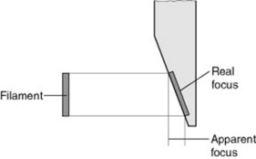
However, the area of the anode from which the X-rays emanate is of definite size, determined by the filament size and the electronic lens system. In both stationary and rotating anode X-ray tubes the face of the anode is not parallel to the filament but at an angle. This ensures maximum efficiency from the tube and reduces penumbra further.
When visualised from a point at the centre of the X-ray beam, the area from which the X-rays emanate (the apparent focal spot size) appears smaller than it actually is (real focal spot size).
MEASURING THE FOCAL SPOT SIZE
This international standard (BS EN 60336:2005)1 applies to focal spots in medical diagnostic X-ray tube assemblies. Methods for evaluating focal spot characteristics operating at X-ray tube voltages up to and including 200 kV are provided in this document.
THE ANODE HEEL EFFECT
The X-ray beam is not uniform over its field – there is a gradual decrease in radiation towards the anode end of the tube. As X-radiation is emitted from the target area in a conical shape, measurements have determined that the intensity in the direction of the anode is lower (over and above the difference caused by the inverse square law) than the intensity in the direction of the cathode. The fact that the intensities vary in such a manner causes visible differences in the density produced on the radiographs. This phenomenon is called the ‘heel effect’ (Fig. 8.7).
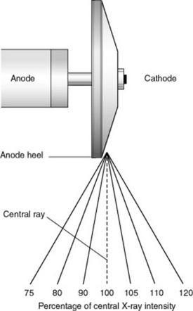
The decreased intensity results from emission, which is nearly parallel to the angled target where there is increasing absorption of the X-ray photons by the target itself. This phenomenon is readily apparent in rotating anode tubes because they utilize steeply angled anodes of generally 17 degrees or less. Generally, the steeper the anode, the more severe or noticeable the heel effect becomes.
THE STATOR ASSEMBLY
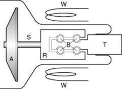
The anode disc needs to rotate at high speed and this is achieved by attaching the anode via a stem to a large copper rotor, which forms the armature of a motor. The target disc, or rotor, is mounted on a shaft, the stem extending from a rotor body which can spin on internal bearings on the rotor shaft. This rotor shaft extends through the end of the insert to the outside of the insert vacuum for connection to the anode wire, and also is the mounting point for the insert inside the housing.
The rotor consists of a copper cylinder and rests in ball bearings for smooth movement. The bearings cannot be lubricated with ordinary grease because it would affect the vacuum and the high-tension characteristics of the tube. Soft metals such as lead and silver are applied to separate the ball bearings and the running surfaces, in order to prevent the possibility of ‘jamming’ in the vacuum. This form of lubrication limits the lifetime of the bearings in the X-ray tube to about 1000 hours.
The exposure switch controls the rotation. The anode only rotates when radiation is required and is braked immediately afterwards. The high inertia of the heavy metal disc leads to some delay in the rotor reaching operational speed. The delay is up to 2.5 seconds, depending on the type of starting device and the anode. An interlock ensures exposure can only take place after the anode has reached its final speed.
The heat of the anode should be prevented from reaching the stator arrangement. The stem is designed to limit the transfer of heat to the rotor assembly; molybdenum is used as it has lower thermal conductivity than tungsten and is made as thin as possible to reduce heat conduction towards the bearings (Fig. 8.8).
THE X-RAY PORT AND COLLIMATOR
X-ray tube assemblies are designed to produce radiation and confine its exit from the assembly via a well-defined portal in the lead lining.
The glass in this area of the tube envelope is ground as thin as practically possible to minimise absorption and this area of the envelope is sited close to the exit portal of the tube housing, separated from it by the cooling oil. At this point there is a window in the housing made of a low beryllium or similar low X-ray absorptive material, which is sealed to the housing to prevent loss of the oil and ingress of air. Beryllium is used due to its low mass absorption coefficient.
BEAM FILTRATION
The total filtration of an X-ray tube assembly (without any additional added filtration) should be not less than 2.5 mm aluminium equivalent.2 On a number of systems, a facility for introducing additional added filtration into the beam (spectral filtering) is provided within the collimator assembly. The additional added filtration may be aluminium, copper or tantalum and may be introduced manually or automatically.
Further added filtration can be particularly useful in reducing patient dose during high dose procedures, such as interventional examinations.
TUBE RATING
The major cause of tube failure can be related to the production of heat and the ability of the tube and housing to remove the heat. Tube rating charts are provided by the manufacturer to indicate safe operating conditions for the tube. The rating charts indicate the maximum exposure times possible at set kV and mA values, these charts need to be used in conjunction with anode cooling charts, which indicate the cooling time required by the anode after an exposure or series of exposures.
ANODE COOLING
The amount of heat stored in the anode at the time of exposure is measured in ‘heat units’ (HU) and this is calculated as a product of exposure (in kV) multiplied by the tube current and time (mA s).
As an example, a typical chest exposure of 90 kV at 2 mA s produces 180 HU, which requires only a short cooling time; however, fluoroscopy at 90 kV for 3 min at 2 mA (360 mA s) produces 32 400 HU and requires a cooling time of over 5 min. Cooling time is exponential with time and depends upon the temperature of the surrounding materials and requires a correction factor for different voltage waveforms. Tube housings also have cooling charts and these are used in a similar manner to the anode cooling charts.
HEAT PATHWAYS IN A TYPICAL ROTATING ANODE X-RAY TUBE ASSEMBLY
In an X-ray tube the point of maximum heat production is at the focal track or focal spot on the anode. The heat produced in this region has to pass from the tube to the surrounding air in order for the tube not to overheat. The heat produced at the focal spot is carried away by radiation to the glass or metal tube envelope and conduction to the body of the anode where radiation to the metal tube envelope occurs. Conduction away from the anode body is minimised by the stem construction and material to prevent damage to the motor bearings.
From the glass envelope heat is dispersed by conduction to the surrounding oil to the tube casing and thereby to the surrounding air by conduction.
The oil in some heavy-duty applications is cooled by a pumped circulation system with a forced air-cooling arrangement; some tube housings are cooled by a forced air fan arrangement to carry the hot air away more quickly.
Most tube housings include a bellows arrangement to allow for the expansion of the oil as its temperature rises in order to prevent damage to the insert or housing. This bellows arrangement includes a micro-switch interlock to prevent further exposures after the oil has expanded by a preset amount, indicating the temperature has risen to a level which could damage the tube.
Bushong S. Radiologic science for technologists: physics, biology and protection. Elsevier: Mosby, 2004.
A modern and up-to-date text from America; good clear descriptions, illustrated well and in good detail.
Forster E. Equipment for diagnostic radiography. Lancaster, UK: Kluwer Academic, 1985.
A very readable text covering the basis of most syllabi.
Meredith J, Massey J. Fundamental physics of radiology. Oxford: Butterworth-Heinemann, 1984.
A ‘classic’ text still popular after 30 years explores diagnostic and therapy physics.
Stockley S. A Manual of Radiographic Equipment. Edinburgh: Churchill Livingstone, 1986.
A popular text with students, clear diagrams outlining basic ideas.
Wilks R. Principles of radiological physics. Edinburgh: Churchill Livingstone, 1987.
A detailed text with thorough explanations of complex ideas with easy to follow mathematics descriptions.