Chapter 12 Films, cassettes, intensifying screens and processing
 Radiographic film is composed of a film base with an active emulsion layer adhered using a subbing layer, with a protective super-coat. Intensifying screens convert the X-rays received into light, which forms the image on the film. This reduces the exposure needed to provide a diagnostic image. The latent image is converted into a permanent visible image through the use of developer and fixer.
INTRODUCTION
Within the imaging department the use of automatic wet film processors to produce a visible image on a conventional film, which is exposed to light originating from intensifying screens held within a cassette, is declining. However, films exposed to a combination of light and X-radiation, using screen film, or directly to X-radiation alone using direct-exposure film, may still be encountered.
FILMS
The production of an X-ray image depends upon the existence of materials that are unstable and, when exposed to light or electromagnetic radiation, change their nature. Halogens such as bromine or iodine are combined with silver to produce silver bromide or silver idobromide.
FILM MANUFACTURE AND SENSITIVITY
Production of emulsion layer
It is essential that film manufacture is stringent and that films of the same type produced in different batches are identical. There are several stages in the formation of emulsion during which the grain size distribution and therefore the contrast and speed characteristics of film are determined. Initially silver nitrate and potassium bromide are added to a gelatin solution. Impurities are then added to create imperfections, known as electron traps or sensitivity centres, within the silver halide crystal lattice. In the latter stages of the process sensitisers that increase responses to specific colours of light or radiation and other agents, such as hardeners, bactericides, fungicides anti-foggants and wetting agents, are added.
Finally, as a result of these processes the emulsion layer, a precipitate of silver bromide within gelatine, is produced.
Spectral sensitivity
The spectral sensitivity of a specific emulsion is the range of wavelengths of the electromagnetic spectrum to which it will respond. Silver bromide crystals are inherently sensitive to the electromagnetic spectrum up to and including blue light, with other colours having a minimal impact.
During the manufacturing process the inherent sensitivity of the emulsion can be extended to other wavelengths by adding a suitable dye, usually to the surface of the crystal. The spectral sensitivity of the film emulsion can be arranged to fall into one of three categories: monochromatic, orthochromatic and panchromatic.
It is essential that the colour of spectral sensitivity of the emulsion and the colour of spectral emission of the intensifying screen be matched in order to obtain maximum film blackening for the minimum exposure.
FILM CONSTRUCTION
Duplitised emulsion
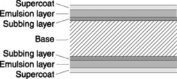
The majority of screen-type film is ‘duplitised’. This type of film has two sensitive emulsion layers – one on each side of base (Fig. 12.1). It is used for most general applications. However duplitised emulsions are also used for intra-oral dental film, although in this instance the film is exposed directly to X-radiation alone.
Film base
This is a thin layer of polyester (polyethylene teraphthalate), which transmits light and provides a support for the other layers.
It is essential that the base should be:
If colour tone is added it should be consistent between batches and not change tone with age. If either were to occur then density and contrast would change.
Substratum or subbing layer
This is a thin, strong adhesive layer that binds the base to emulsion. It plays a vital role in ensuring that these do not separate whilst processing, as the emulsion layer absorbs warm chemicals and swells. This layer is usually a mixture of the film base solvent and gelatin. A coloured dye may be included within this layer to reduce the amount of light transmitted from one emulsion layer to the other, reducing the crossover effect.
Emulsion layer
This is a suspension of light/radiation-sensitive silver halides suspended within a gelatin binder. The use of tabular (flat-shaped) silver halide crystals with a larger surface area–volume ratio, provides significant advantages including:
Supercoat/anti-abrasive layer
This is a very thin coating of hardened gelatin. It protects the sensitive emulsion layer against mechanical damage that can arise from handling and transport within manual and automatic film loaders and processors. However, two issues arise:
Single-sided emulsion
Single emulsion
Single-sided film, with one emulsion layer, may be used when a single intensifying screen is used; for example in mammography where high resolution is imperative and in instances when an image of a light source (laser source, photofluorographic) is required. All films consist of a number of discrete layers.
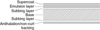
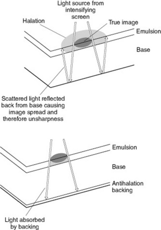
This is similar in construction to duplitised film; however, the second emulsion layer is replaced with an anti-curl/halo backing (Fig. 12.2). Curl may occur during processing as the emulsion layer absorbs processing chemicals and water and expands to a certain degree. To avoid this a layer of gelatin of identical thickness to the emulsion layer is applied to the non-emulsion aspect of the film. During processing this will expand to the same degree as the emulsion, ensuring that the dry film will lie flat. In single-sided emulsions light can be reflected at the base–air interface, back towards the sensitive emulsion layer, thus creating a halo effect (Fig. 12.3).
To minimise the halo effect a coloured dye is incorporated within the gelatin of the anti-curl backing. This acts as a colour filter and absorbs light of specific wavelengths, increasing the resolution of the image. The dye colour utilised is always the opposite colour to the exposing light source; for example yellow dye to absorb blue light. The anti-halation dye is bleached out in the fixer during the processing cycle. Processors that process large numbers of single-sided films require a higher fixer replenishment rate than those that primarily process duplitised films, as the removal of anti-halation dye utilises more fixer energy.
Advantages of using duplitised emulsions
The use of ‘duplitised’ emulsions results in increased film speed and blackening for a given exposure because the amount of emulsion available for exposure enhances sensitivity. This effect is enhanced further when the film is sandwiched between a pair of intensifying screens and provides several potential benefits in that:
Image resolution and use of films
No radiographic image is truly sharp and all images are to some extent blurred as a result of imperfections within the imaging system itself.
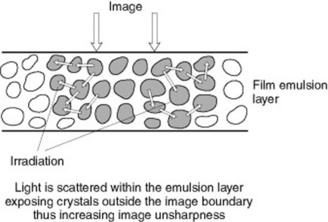
Irradiation
This is the sideways scattering of light within the emulsion layer as a consequence of light striking the silver halide crystals (Fig. 12.4). This is a cause of image unsharpness, as the scattered light does not contribute to the primary image.
Halation
Halation occurs when an image is formed by light and some of this incident energy passes through the emulsion to the base. On reaching the base–air interface this light either passes out of the film or is reflected back towards the emulsion layer where it creates unsharpness by interacting with silver halide crystals.
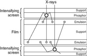
Crossover
Crossover creates an increase in image unsharpness because light that is not completely absorbed in the emulsion layer nearest to source of light passes through the film base and subsequently interacts with silver halide crystals in the opposite emulsion layer, creating a wider and thus less sharp image (Fig. 12.5).
Parallax
Parallax is unsharpness caused by the separation of the two images recorded on duplitised film. There is an element of spatial separation between these images, and when subsequently viewed this separation creates a small degree of blur. In reality, the distance involved in image separation is very small, thus the blurring effect is negligible.
CASSETTES
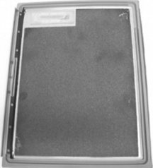
In radiographic terms a cassette normally houses and provides a physically safe and light-tight environment for both the film and the intensifying screens in which the processes associated with fluorescence and the formation of the latent image can occur (Fig. 12.6). Cassettes are available in various sizes and with detailed differences between specific manufactures.
CONSTRUCTION
INTENSIFYING SCREENS
Intensifying screens operate by converting X-ray energy into light photons. This occurs within the phosphor layer of the intensifying screen where the X-ray photons are absorbed by the phosphor crystals. This causes the crystals to become excited and luminescence occurs. Luminescence is the ability of a material to absorb short wavelength energy (X-radiation) and emit longer wavelength radiation (light). This process facilitates a gain within the imaging procedure as each X-ray photon that is absorbed releases many light photons, thus allowing the radiation dose to the patient to be reduced. In reality, approximately 95% of film blackening is created by light emitted from the phosphor layer and 5% by the direct effect of X-radiation.
CONSTRUCTION OF INTENSIFYING SCREENS
The detailed construction of an intensifying screen can vary widely; it is, however, closely related to its planned use in clinical practice and comprises a number of discrete layers (Fig. 12.7).
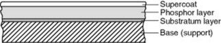
Supercoat
A thin, transparent waterproof layer of cellulose acetobiturate extends around the sides (as an edge seal) and the back of the screen, encasing it completely. It forms an effective seal against a variety of fluids, any of which could seriously damage the screens. It also provides a limited degree of physical protection to the delicate phosphor layer. Light from the phosphor layer is able pass through this thin transparent layer easily, with minimal distortion, thus helping to minimise unsharpness. It is easy to clean and a poor generator of static electricity.
Phosphor layer
This layer consists of the phosphor crystals; suspended in a transparent binding material such as polyurethane. The nature of the phosphor crystals will vary depending upon the planned spectral emission of the intensifying screen. The speed of the intensifying screen will depend upon both the type of phosphor crystal used and the density to which they are packed. Within high definition intensifying screens the use of coloured pigment or carbon granules in the binder material tends to absorb laterally scattered light within the phosphor layer. This minimises photographic unsharpness but requires an increase in radiation exposure to the patient.
Substratum
This forms the bonding layer between the base and the phosphor layer. It will vary depending on the intended use for the screens in that it may be absorptive, reflective or just transparent in nature.
When absorptive in nature a coloured dye is added to the substratum, which tends to prevent light that is travelling away from the film emulsion layer from being reflected at the base–phosphor interface back onto the film. This aids in the reduction of photographic unsharpness and is found in some high-definition type (slow) intensifying screens.
The reflective function is used in some high speed (faster) intensifying screens. Titanium dioxide or a similar white pigment is incorporated into the substratum. This acts to reflect light that is travelling away from the film emulsion layer back towards the film emulsion, reducing the radiation dose received by the patient but increasing photographic unsharpness.
PHOSPHOR TYPES
It is essential that the materials used as phosphors are very efficient at absorbing X-ray photons and have high quantum detection efficiency. The phosphors should also be efficient at converting X-ray photons into light and exhibit minimal afterglow.
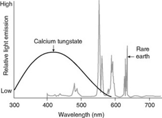
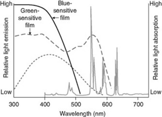
Modern rare earth phosphors, such as gadolinium oxysulphide, lanthanum oxybromide, yttrium oxysulphide and others, generally have both a higher detection and conversion efficiency than the older mostly blue/violet-light emitting materials such as calcium tungstate or barium lead sulphate. Rare earth phosphors are normally used in conjunction with a small amount of an activator, the combination of which determines both the spectral emission, colour of the emitted light, and its intensity of luminescence. For example a combination of gadolinium oxysulphide with terbium as an activator emits green light whilst lanthanum oxybromide with thulium emits blue light. Rare earth phosphors tend to emit the majority of light produced at discrete wavelengths and are referred to as ‘line emitters’, whilst older type materials, such as calcium tungstate, emit light continuously between specific wavelengths and hence are ‘broad spectrum emitters’ (Fig. 12.8).
MATCHING FILM SPECTRAL SENSITIVITY AND SPECTRAL EMISSION
It is essential that the film’s sensitivity is matched directly to the spectral emission of the intensifying screens in order to achieve maximum filmblackening from a given radiation exposure to the patient (Fig. 12.9). When an orthochromatic-type film is used with intensifying screens emitting green light it can be seen that the majority of the light emitted by the intensifying screens lies within the spectral sensitivity curve of the film. This ensures optimal performance of the system. However, if a monochromatic-type film is used with the same intensifying screens, the majority of the light emitted by the screens lies outside the film’s spectral sensitivity curve. Therefore, most of the emitted light will have minimal impact on the silver halide crystals within the film’s emulsion.
TYPES OF INTENSIFYING SCREEN
Variations in the construction of the intensifying screen will produce screens with different characteristics for specific use.
Enhanced image resolution may be achieved by the use of absorptive material within the substratum and inclusion of coloured dyes within the binding material of the phosphor layer. Except in special circumstances, intensifying screens are paired facilitating the use of duplitised film emulsions (see p. 136). In such circumstances the back intensifying screen will receive slightly fewer X-ray photons than the front screen due to absorption within both the front screen and the film itself. Thus the two images may be of a slightly different density. Manufacturers may either choose to ignore this and produce a pair of screens of identical speed. Alternatively they may opt to increase the speed of the back screen by the use of a reflective layer or greater coating weight or use a pigment to reduce the speed of the front screen.
RADIOGRAPHY WITH A SINGLE INTENSIFYING SCREEN
Mammography is the exception to the general norm that screens are always used in pairs. In this case a single-sided film emulsion is used in conjunction with a single intensifying screen with the prime aim being to reduce photographic unsharpness. The normal arrangement is for the intensifying screen to be positioned behind the film. This helps to reduce photographic unsharpness, because the light emission from the phosphor crystals has a shorter distance to travel prior to interacting with the silver halides within the film emulsion.
INTENSIFYING SCREENS AND IMAGE RESOLUTION
The use of screens plays a significant role in reducing the radiation dose received by patients. The following features of their construction make a significant contribution to the final image resolution:
As the speed of the system increases then in general terms resolution is reduced. However, as with many aspects of imaging, a balance has to be struck between the competing considerations and the need to produce an image that is of a diagnostic quality.
QUANTUM MOTTLE
This arises when a very fast imaging system is utilised and a relatively small radiographic exposure is required. It occurs when a relatively small number of X-ray photons in the beam transmitted by the object are available to interact with the phosphor crystals. Thus the number of light photons available to interact with silver halides declines and the resultant image may be grainy, mottled or even unrecognisable.
CARE OF INTENSIFYING SCREENS
Intensifying screens are relatively delicate and as such must be handled with care. Most opening/closing occurs within film loaders, reducing the opportunity for damage to screens. If a need to open a cassette arises then this should occur in areas away from dust or liquid, which may cause contamination.
Internal cleaning is necessary to remove small artefacts that often appear as small white spots on the subsequent image and have a detrimental effect on image quality. The manufacturer’s instructions relating to the procedure and cleaning agent should be followed. It is essential that the cassette is not reloaded and closed until both screens are completely dry. If a screen becomes damaged then it is irreparable and both screens within the cassette will need to be replaced, which is time consuming and expensive.
PROCESSING
The final stage in the production of a hardcopy X-ray image is processing. Automatic processing is often linked to a daylight handling system for the loading and unloading of cassettes.
Whilst passing through the automatic processor the film is subjected to a number of processes during which the latent image is changed into a visible format.
DEVELOPMENT
Development is the initial stage in the processing cycle which converts the latent image into a visible form. This involves a process of electron donation by which the exposed silver halide crystals are reduced to metallic silver whilst the unexposed silver halides remain unchanged. An exposed silver halide crystal possesses a weakness in its negatively charged ion barrier caused by a collection of silver atoms at the crystal’s sensitivity centre. Electrons from the developing agent are able to penetrate the exposed silver halide and convert it into silver. Unfortunately, the developer is not entirely effective at differentiating between exposed and unexposed silver halide grains. The development of unexposed crystals contributes to the overall image density whilst reducing the contrast of the film.
The developer solution has various constituents including:
Undesirable changes to the pH level of developer solution may occur as a result of both aerial oxidation and the acid by-products of the development process. Within modern developers the use of carbonates as accelerators and sulphides as preservatives counteracts the potential effects that could arise from changes in the pH of the solution.
FIXATION
Major functions of fixation include:
Constituents of fixer
WASHING
This stage is designed to remove both residual fixer chemicals and silver salts from the film emulsion. This process is not 100% effective and residue salts can adversely affect the archival permanence of the resultant image, causing a brown stain. Therefore, the aim of washing is to reduce level of the residual salts to such an extent that they will not create staining during the expected life of the film. Washing is most effective when the film is exposed to a continuous flow or spray of uncontaminated water, as the diffusion of residual salts from the emulsion layer is more effective in clean water.
AUTOMATIC PROCESSORS
The basic components within an automatic processor are very similar despite the differences that occur between manufacturers products in relation to design and film capacity (Fig. 12.10).
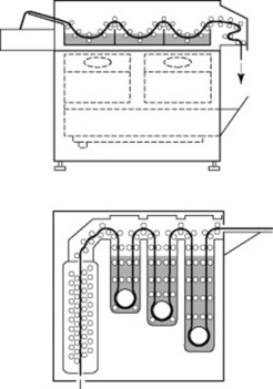
MAIN CONTENTS OF THE PROCESSOR
The processor is essentially a light-tight box containing:
DEVELOPER SECTION
Temperature control
To maintain image quality temperature must be maintained within 0.5 °C. An immersion heater working in conjunction with a thermostat may achieve this. Alternatively, a heat exchange unit may be used.
Drainage system
This facilitates the emptying of the tank for routine cleaning and maintenance. It is usually a length of plastic tubing which is screwed into a drain hole in the base of the tank. It may also act as an overflow pipe.
FIXER SECTION
The fixer section contains drainage, recirculatory and replenisher systems that are similar in function to those within the developer section (Fig. 12.13). The temperature control will be dependent on the design of the processor and may utilise heat exchange from the surrounding warm developer and wash tanks. In the case of cold-water wash units the temperature control is achieved by using an immersion heater thermostat device, with insulation provided in the dividing wall between the fixer and wash sections. The precise control of fixer temperature is not as critical as it is for developer solution.

WASH SECTION
This section aims to remove both residual fixer complexes and silver complexes; thus improving archival permanence of the film. Differing types are available including:
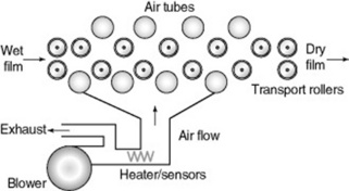
DRYING SECTION
There is danger to the film emulsion if the air used for drying is too hot. A microswitch is present to prevent film damage. There are a number of different systems available to dry films (Fig. 12.14).
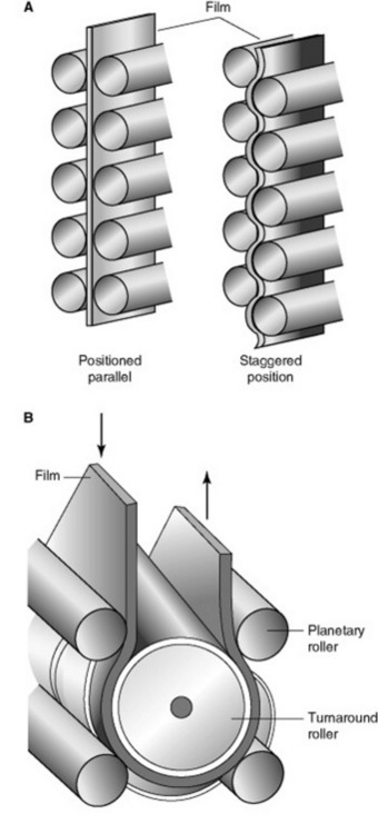
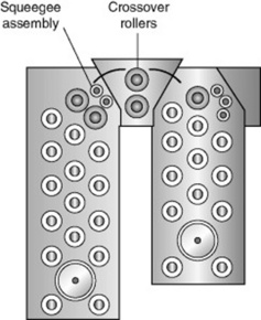
TRANSPORT SYSTEM
The film transport system comprises a series of rollers arranged in racks, driven by an electric motor at a constant speed (Fig. 12.15).
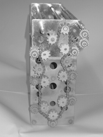
The arrangement of the rollers may vary and includes staggered or face-to-face. The deep or vertical rack system is the most common and is associated with high-capacity processors. During the processing cycle the film is required to change direction at the top and bottom of the tanks. In these situations plastic or stainless steel guide plates are utilised to guide the film through 90° directional changes. Rollers fit into distinct categories:
Squeegee rollers play an important part in reducing carry-over rate of chemicals. As a safety measure, a microswitch prevents roller operation if the lid of the processor is not in place.
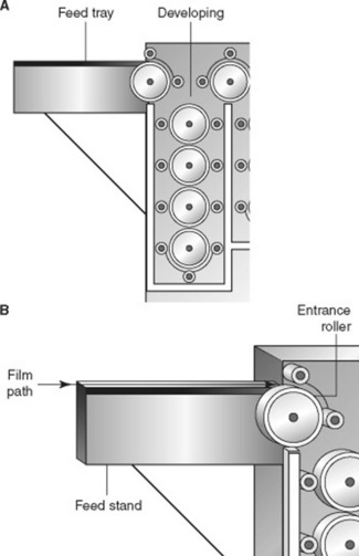
FILM FEED SYSTEM
This system activates all the main processor functions and, in instances when manual loading of the processor occurs, gives an audible signal that it is safe to feed another film into the processor (Fig. 12.16). Different systems are utilised to achieve this, including:
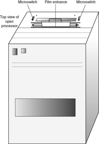
REPLENISHMENT SYSTEM
As a film passes through the beam is broken. This calculates the film size and the required amount of replenishment. As films are processed then the nature of both the developer and fixer solution is subject to change. This occurs because the by-products of the process can alter the nature of the solution. Some solution is carried over on the film, reducing the amount present in the tanks and causing some contamination. Developer solution can become less active as it oxidises in the air and so constant replacementis essential. In order to maintain both solution activity and level, replenishment of solutions is essential (Fig. 12.17). Replenishment may occur whilst each film is fed into the processor when the microswitch is activated or is related to the area of film processed as calculated by infrared detector. The latter is the most accurate method.
MICROPROCESSOR CONTROL
Microprocessors can be used to monitor and display the performance of specific aspects of the unit, including temperature of solutions, dryer temperature, solution levels and transport speed.
STANDBY SYSTEM
This is designed to save energy and water, thus enhancing the efficiency of the operation of the processor by reducing the operating costs. Wear and tear on the system is also kept to a minimum. The system automatically shuts down some of the processor functions, including water supply, transport and circulation systems and dryer, if a film has not entered the processor within a prearranged time interval. The system will switch on again once a film enters the processor or after a predetermined time out of use, thus maintaining processors in a state of immediate readiness for use.
AUTOMIXERS (CHEMICAL MIXERS)
Mixers (Fig. 12.18) may differ in construction and mode of operation but all systems provide:

CARE AND MAINTENANCE OF THE AUTOMATIC PROCESSOR AND CHEMICAL MIXER
Routine maintenance, including regular servicing and actions taken by departmental staff, plays a vital role in the maintenance of image quality. Departmental protocols and manufacturer’s instructions relating to care and maintenance may vary considerably. It is vital that these instructions are followed. It is essential that the unit is switched off and isolated from the mains prior to any work commencing.
AUTOMATIC PROCESSOR CARE
These are guidelines; the specific care provided by manufacturers should be followed.
Daily
Weekly
In addition manufactures recommend the periodic drainage and cleaning of fixer and developer tanks.
PROCESSOR QUALITY CONTROL
Slight variations in operating parameters can produce a significant effect on final image quality. Many processors are capable of displaying a range of information relating to their operating parameters. It is vital that a record is kept of all checks and data obtained during processor monitoring activity. During all routine maintenance activities a general visual check should be made of all aspects, especially those relating to the drive mechanism.
Routine assessment should also be made of:
A change to the nature of processing solutions occurs as a result of use; solution replenishment is designed to maintain the maximum function of both developer and fixer. Checks on processing chemistry include:
SENSITOMETRIC TESTS
These may be used to determine the actual function of the processor. This involves the production or purchase of 21-step control strips. The process may be computerised or manual.
Computerised
In these circumstances a strip reader is utilised to determine fog level, speed and contrast when a processed 21-step sensitometric control strip is fed into the unit. The information gleaned from the strip is used to produce and evaluate a characteristic curve. The unit may also indicate whether the curve is within normal limits and, if not, the potential remedial action that should be taken.
Manual
This requires the use of a densitometer, and as the density of specific parts of the image must be recorded manually it is a somewhat lengthy and time-consuming procedure. Results are used to plot graphs that investigate trends by recording the fog levels, density and contrast (Fig. 12.19).
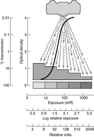
Parameters assessed
Fog is determined by measuring the density of a part of the film that has not been exposed during the production of the strip. This density is used to form a base line for subsequent records. The test is performed daily and on subsequent days the density of an identical part of the film is measured and plotted on the graph.
Film speed is a sensitive indicator of variations in developer solution activity. The density of steps is determined and the step with the nearest to a density of 1.0 plus basic fog is selected. The density of this step is recorded on the graph. On subsequent days the density of the same step number is measured and recorded on the graph.
Selecting two steps and measuring the density of each can assess contrast. It is better to avoid the use of adjacent steps because density differences may be very small. The lowest density figure is then subtracted from highest, with the difference being plotted on the graph. On subsequent days the density of the same step numbers are measured and the differences recorded on the graph.
HEALTH AND SAFETY CONSIDERATIONS
It is essential that an assessment of the health and safety risks associated with a given procedure be undertaken prior to working with processing chemicals. Staff must be adequately instructed to undertake the task and safety equipment should be provided and utilised. Information relating to the actions to be taken in the event of an accident should be clearly displayed. Regular monitoring of the working environment should occur to ensure that occupational exposure standards are being maintained.
Ball J, Price T. Chesneys’ radiographic imaging, 6th edn. Oxford: Blackwell Science, 1998.
This text provides a clear description of all aspects of processing and films..
Gunn C. Radiographic imaging: a practical approach, 3rd edn. Edinburgh: Churchill Livingstone, 2002.
Environmental Protection Act 1990. London: HMSO.
The Control of Substances Hazardous to Health Regulations 2002 (SI 2002/2677). London: HMSO.
These three documents should all be consulted, as their contents are applicable to the use and disposal of processing chemicals and water..