Chapter 13 Digital radiography
 Most hospitals within the UK are now completely film-less or in the process of replacing film with various digital systems. Digital images can be viewed rapidly, manipulated quickly (annotated, cropped), then sent to a computer network for reporting and viewing. The introduction of teleradiography means that images can be viewed and reported on around the world, thus making use of international expertise and collaboration. Mammography is currently one area where film is still being used quite extensively, although this is expected to change within the next few years. There are two types of digital imaging in use: computed radiography (CR), and digital radiography (DR).
INTRODUCTION
As with the recent developments with general photography, where digital cameras are replacing film, this technology is also being used to replace X-ray film with digital imaging. Digital imaging has already been in use for many years in computed tomography (CT), magnetic resonance imaging (MRI), nuclear medicine (NM), fluoroscopy and ultrasound, but only recently has conventional X-ray equipment started to use digital technology.
Digital radiography has greater exposure latitude than X-ray film; therefore any over- or underexposure of an image can still be viewed. However, there is a trade off between radiation dose and image quality, as high exposures will give a very clear image but an unacceptable dose to the patient. Low exposures will result in a noisy (grainy) image and may miss diagnostically significant information. This is an advantage over the traditional film–screen combination where any exposure in the foot or shoulder areas of the characteristic curve will result in no usable image being obtained (Fig. 13.1).

COMPUTED RADIOGRAPHY
Computed radiography (CR) has been used as a direct replacement in areas where previously film was used. It uses storage phosphor cassettes in standard X-ray rooms and has allowed radiology departments to make the transition from film to digital imaging without significant equipment changes.
THE IMAGING PLATE
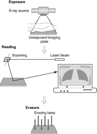
The imaging plate is coated with a photostimulable phosphor (PSP), which captures X-rays once they have passed through the patient or object being imaged (Fig. 13.2). The PSP material has been ‘doped’ with small amounts of impurities which alter the physical properties of its crystalline structure.
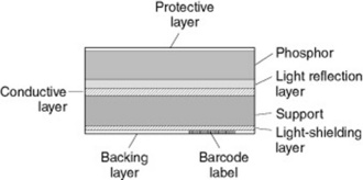
A PSP material has a high absorbance at the energies used for diagnostic radiology and is able to store the irradiated energy and then release it as visible light in response to the stimulation of a beam of laser light within the reader. The family of europium doped barium fluorohalides fits these criteria – BaFX, where X can be chlorine (Cl), bromine (Br) or iodine (I).
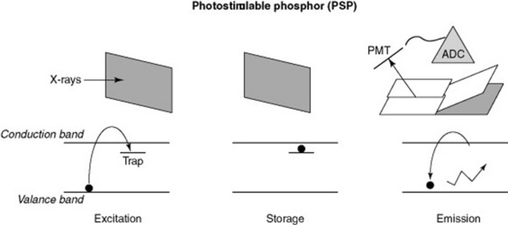
As the X-rays pass through the PSP material, they interact with the electrons in the crystalline structure, giving them energy, which enables them to enter the conduction band. Some electrons return immediately to the valence band, but others remain ‘trapped’ in the forbidden zone between the two bands (Fig. 13.3). This trapped signal is proportional to the amount of radiation incident on the plate; these electrons form the latent image in the PSP.
RETRIEVING THE LATENT IMAGE
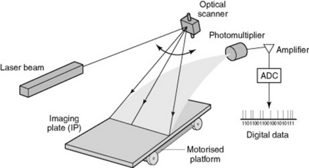
To retrieve the latent image from the PSP it is placed in a CR reader, where a laser scans it (Fig. 13.4). The laser gives the electrons enough energy to return and leave the traps and to decay down to the ground or valence state. As these electrons move down in energy a blue light is emitted. This light is collected by a light guide and directed towards the photomultiplier tube. The light moves through the photomultiplier, is then amplified and then the signal is digitised using an analogue-to-digital converter, allowing the temporary storage of the image in digital format. This can then be sent to a monitor for viewing or to a printer.
ERASURE OF THE PLATE
Unfortunately the read out with the laser does not clear all the trapped electrons, as there are traps at many different energy levels that do not respond to the energy of the laser light beam. The remaining electrons are removed using a bright white light, which has enough energy to pass through the PSP and all the traps will respond. This removes any residual signal from any previous images. It should also be exposed to this bright light, a ‘primary’ erase, to prevent build-up of background signals over time.
CARE OF THE IMAGING PLATE AND CASSETTE
All manufacturers have a suggested cleaning and maintenance procedure and it is important to follow their guidance and use the recommended products in order not to invalidate any warranty or guarantee.
CR plates should be checked regularly for damage, as part of a departmental quality assurance programme, and removed from use or repaired if damage is found. The imaging plates also need regular checks because they are removed from the cassette each time they are read – edges tend to get damaged, cracks can appear and they can be vulnerable to scratches. Once again any damaged plates must be removed from service. There have been reported problems with cassette catches opening and the plates dropping out, so these must be checked and cleaned before being returned to service. Imaging plates have an estimated life of 10 000 exposures (manufacturer dependent), so it is important to make sure cassettes are rotated and used evenly throughout a department.
With CR the detector is separate from the imaging device and incorporates extra stages to the production of an image, digital radiography removes the need for a cassette and a reader from this process.
IMAGING THE PATIENT USING CR
The patient is registered to each imaging plate used by means of an individual barcode on each plate, using the patients’ hospital number. X-rays are then taken, the operator inputs into the CR reader the views that have been taken (e.g. chest X-ray (CXR), abdominal X-ray (AXR)) and the plates are then placed in the CR reader, which picks up the barcode and allocates images to the correct patient, along with the correct protocol for image processing (Fig. 13.5).
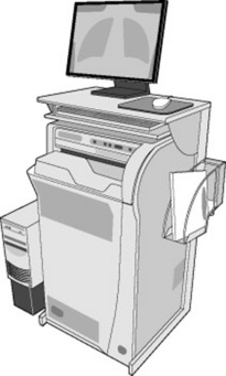
The CR reader then removes the plate from the cassette and this is read out as previously described. The image is subsequently viewed on an acquisition workstation where it is cropped and markers applied (i.e. L or R, PA, AP, etc.). The image can be checked for quality and dose indicators, such as sensitivity or exposure index (manufacturer dependent). Once the radiographer is satisfied that the image is correctly identified, manipulated and annotated, it is then sent on to the network for reporting and storage for retrieval at a later date from anywhere within the network (Fig. 13.6).
DIGITAL RADIOGRAPHY
Currently there are two types of system utilised for digital imaging:
The image receptor is usually an integral part of the X-ray equipment so it is more expensive to implement than CR.
INDIRECT DIGITAL RADIOGRAPHY
Indirect digital radiography (IDR) uses a phosphor (caesium iodine, CsI), which is coated over an active matrix array (AMA) of amorphous silicon (a-Si) (Fig. 13.7).
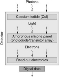
Image production
Disadvantages of using IDR systems
Scatter can be a problem with this system and the amount can depend on the thickness and structure of the phosphor material; however, this will be less than with screen film. Noise on the image can also be an issue but cooling the detector can reduce this. Systems are currently restricted by size as each photo-diode represents one pixel in the image, and images are several mega- or even giga-pixel sized. Therefore spatial resolution is restricted due to the physical size of the photo-diode and the pixel.
DIRECT DIGITAL RADIOGRAPHY
Direct digital radiography (DDR) does not use a phosphor material; the X-ray photons are directly converted into an electrical charge. The detector material used is amorphous selenium (a-Se) which is coated on a thin-film-transistor (TFT) array (Fig. 13.8).
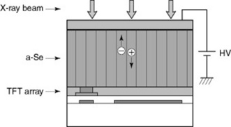
A bias voltage is applied across the detector structure and as the X-rays pass through they directly generate positive and negative charges which are in proportion to the level of X-ray exposure. The positive charge is drawn to the capacitor where it is stored and readout by the customised electronics within the array. The imaging plate is made up from millions of these detectors causing variations between them. Software is available to smooth out the differences between the detectors on the plate. This smoothing process is known as ‘stitching’. As with CR, the patient images are checked, annotated and sent onto the computer network for reporting and storage.
COMPUTED RADIOGRAPHY VERSUS DIGITAL RADIOGRAPHY
Computed radiography is cheaper to implement than any DR system and CR is seen as a direct replacement for film. In some areas it can be seen as being cost neutral, owing to the saving made from not purchasing processing chemicals and film. There have also been health and safety gains by the removal of film processing equipment, the reduction in chemical vapours in the workplace and disposal of used chemicals.
DR necessitates the replacement of the entire X-ray unit (normally), so the process of implementation will be slower as it is probable that it will be installed as part of an overall equipment replacement plan, which could take many years. Radiology departments which are film-less tend to have a combination of CR and DR technologies. This helps with training issues, as CR is less of a step from the conventional film-screen techniques than DR. Staff need to be able to utilise the new technology and get accustomed to softcopy viewing and reporting. This must be factored into the installation costs and timescales in order to ensure full and best use of the equipment.
Both CR and DR have the scope to reduce the radiation dose, when compared to film-screen imaging, although they have not yet shown significant dose reduction. In fact it has been reported that a phenomenon known as ‘dose creep’ has started to happen; operators have been increasing the exposure factors to improve image quality, and radiologists and consultants have come to expect to see good high quality images. CR and DR have fairly comparable resolution and efforts are being made to improve this with new technology and materials used.
PACS – PICTURE ARCHIVING AND COMMUNICATIONS SYSTEM
PACS is the system predominately used for the image acquisition, image display, the network and storage and retrieval of images in most hospitals and clinical environments. Implementation of PACS has become widespread and has resulted in the use of softcopy display for reporting and display (Fig. 13.9).
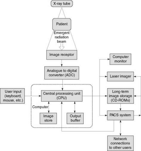
Figure 13.9 Typical set-up of a picture archiving and communications system (PACS) in the clinical environment.
IMAGE DISPLAY
As with the image production, the viewing display must be seen as the final part of this process for the reporting workstations. These displays must be able to manage large data files, be able to show the full resolution and greyscale levels of the image and have a fast response to manipulation of the images. For subsequent image reviewing the high quality is not so important so standard PC monitors are acceptable.
Viewing conditions must be optimised where possible for reporting workstations: they must be in an area of low ambient light, with little or no reflection off the screen from other light sources. They should be part of a quality assurance programme to ensure viewing conditions remain satisfactory throughout the monitor’s lifespan.
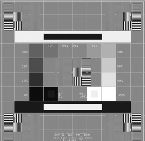
The reporting monitors must be checked daily using a recognised test pattern such as the SMPTE test pattern (Fig. 13.10). There should be checks for distortion and centring, by verifying that all 11 luminance patches are visible. It should be checked that the 5% and 95% patches can be seen and the visibility of the high and low contrast line pair patterns should be assessed.
DICOM – DIGITAL IMAGING AND COMMUNICATIONS IN MEDICINE
This is the industry standard for protocols between different systems. It enables modalities within a radiology department to communicate with each other and so would apply, for example, between CT and ultrasound. DICOM enables images to be displayed on the PACS system regardless of the type of image and the equipment manufacturer. It is therefore important that during any equipment purchase phase the DICOM standard must be stipulated as an essential requirement to ensure compatibility.
EPR – ELECTRONIC PATIENT RECORD
The EPR is a programme available in many NHS hospitals and it is planned to be linked to all UK hospitals, allowing patients’ records and notes to be available wherever they may be treated. PACS will become a part of this and allows the radiology images to be viewed alongside the patients’ notes. The EPR has been designed to integrate the existing HIS (hospital information systems) and RIS (radiology information systems) into one single system.
Further reading and information
Bushong SC. Radiologic science for technologists, 8th edn. St Louis: Mosby, 2004.
This text provides a well-illustrated and informative chapter covering all aspects of digital imaging..
Oakley J. Digital imaging. Cambridge: Cambridge University Press, 2003.
An informative and extensive text covering everything you need to know about digital imaging in one place..