Explanations for Use
This handbook is intended as a quick reference and review and assumes that each user has successfully completed, or is now completing, courses in radiographic positioning and procedures.
Radiation protection: Certain radiation protection practices and shielding descriptions are included with each projection and it is the responsibility of the technologist to ensure that maximum shielding is used wherever possible.
Patient doses: Methods to reduce effective dose including collimation, shielding, and technical considerations given for each projection. (See Appendix A for more details.)
kV ranges: Suggested kV ranges for analog and digital systems are stated for each projection. These are estimates based on common practice from several facilities and validated by imaging experts. These kV ranges may not apply to every department protocol or imaging systems employed. The technologist should consult with their radiation safety officer or supervisor to determine appropriate kV ranges for their clinical setting.
Chapter title pages: The list of projections with page numbers is at the beginning of each chapter for ease in locating specific projections and also as a reference for marking the basic department routines for each examination. A small check √ can be placed in the box by each projection that is part of the preferred departmental routine. Each projection is also followed with either an (R) or a (S) for a suggested departmental routine or special.
Standard Radiographic Image and Evaluation Criteria: With each positioning page is a standard radiograph of that projection. Viewing this radiograph and comparing it with the list of evaluation criteria to check leads the user through a critique of the image they are reviewing by comparing it to the standard radiograph.
Also included is an optional competency sign-off area to be signed by the clinical instructor for individual student competency records.
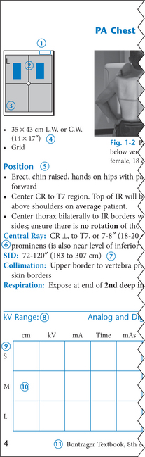
Each positioning page has a format similar to this sample page.
 Suggested location of patient ID info. For chest exams this represents the top right of the image receptor (IR).
 Recommended AEC chamber(s) (darkened R and L upper cells indicated on this PA chest example). Note: Verify AEC chamber selection with department before employing.
 Collimation field size with CR location in center.
 IR size recommended for average adult, placed lengthwise (L.W.) for portrait, or crosswise (C.W.) for landscape in reference to the patient. Grid or nongrid.


 Suggested kV ranges. Analog and digital systems. (Pencil in kV range for your imaging systems.)
 Imaging factors to be filled in (in pencil) as determined best for small (S), medium (M), or large (L) patients, or for specific rooms.
 This additional space is provided for exposure factors for analog systems or for specific types of digital image receptors that require technique adjustments.