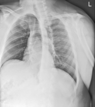
Chest
 PA (R)
Chest—Positioning Considerations and Radiation Protection*
Restricting the primary beam coverage is a very effective way to reduce patient exposure in chest radiography. This requires accurate and correct location of the central ray (CR).
Correct CR Location
Correct CR location to the midchest (T7) allows for accurate collimation and protection of the upper radiosensitive region of the neck area. It also prevents exposure to the dense abdominal area below the diaphragm, which produces scatter and secondary radiation to the radiosensitive reproductive organs.
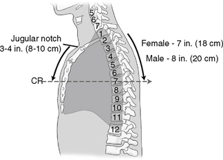
T7 for the PA chest can be located posteriorly in reference to C7, the vertebra prominens. Level of T7 is 7-8 inches (18-20 cm) below the vertebra prominens.
The CR for the AP chest is 3-4 inches (8-11cm) below the jugular notch and angled 3°–5° caudad.
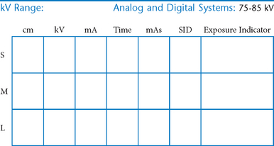
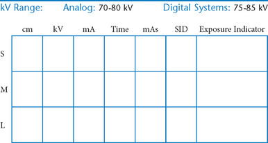
Digital Imaging Considerations*
The following technical factors will reduce dose to the patient and improve image quality:
Collimation:
Close collimation reduces dose to the patient and scatter radiation reaching the image receptor.
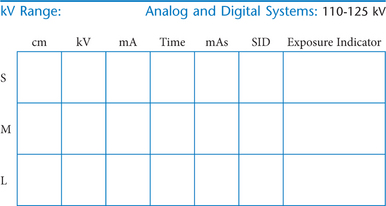
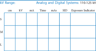
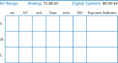
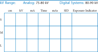
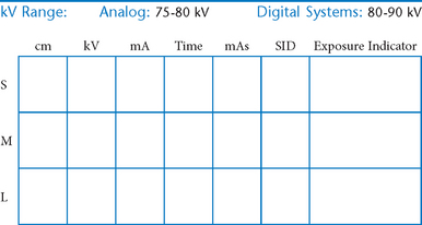
kV Range:
Digital systems allow the use of higher kV as compared to analog (film-based) systems, which will reduce patient dose.
Exposure Indicator:
Check the exposure indicator to verify that the optimal exposure factors were used to produce the least amount of radiation to the patient.
Grids:
Grids generally are not used with analog (film-screen) imaging for body parts measuring 10 cm or less. However, with certain digital systems, the grid may or may not be able to be removed from the receptor. In those cases it is departmental protocol that determines if a grid is left in place or removed.
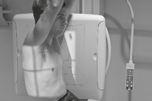
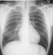
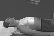
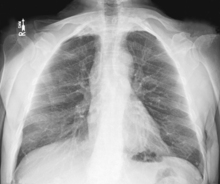
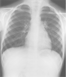
PA Chest*
Position
• Erect, chin raised, hands on hips with palms out, roll shoulders forward
• Center CR to T7 region. Top of IR will be approximately 2″ (5 cm) above shoulders on average patient.
• Center thorax bilaterally to IR borders with equal margins on both sides; ensure there is no rotation of thorax.
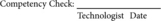
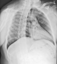
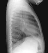
Lateral Chest*

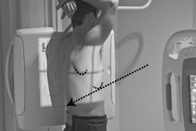
Position
• Erect, left side against IR (unless right lateral is indicated)
• Arms raised, crossed above head, chin up
• True lateral, no rotation or tilt. Midsagittal plane parallel to IR (Don’t push hips in against the IR holder.)
• Thorax centered to CR, and to IR anteriorly and posteriorly
Central Ray:
CR ⊥, to midthorax at level of T7. Generally IR and CR should be lowered ≈1″ (2.5 cm) from PA on average patient.

Lateral, Wheelchair or Stretcher*
Position
• Erect, on stretcher or in wheelchair
• Arms raised, crossed above head, or hold on to support bar
• Center thorax to CR, and to IR anteriorly and posteriorly
• No rotation or tilt, midsagittal plane parallel to IR, keep chin up
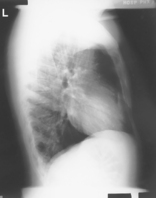
Lateral Decubitus*
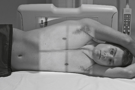
Position
• Patient on side (R or L, see Note) with pad under patient
• Ensure that stretcher does not move (lock wheels)
• Raise both arms above head, chin up
• True AP, no rotation, patient centered to CR at level of T7

AP Lordotic*
Position
• Patient stands ≈1 ft (30 cm) away from IR, leans back against chest board
• Hands on hips, palms out, shoulders rolled forward
• Center midsternum and IR to CR, top of IR should be 3-4″ (8-10 cm) above shoulders

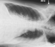
AP Lordotic Chest
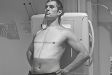
Anterior Oblique Chest (RAO and LAO)*
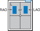

Position
• Erect, rotated 45°, right shoulder against IR holder (RAO) (Certain heart studies require LAO, 60° rotation from PA.)
• Arm away from IR up resting on head or on IR holder
• Arm nearest IR down on hip, keep chin up
• Center thorax laterally to IR margins; vertically to CR at T7

Anterior Oblique Chest—RAO and LAO
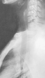
AP and Lateral Upper Airway (Trachea and Larynx)*

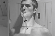
Position
• Erect, seated or standing, center upper airway to CR
• Arms down, chin raised slightly
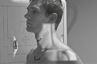
AP and Lateral Upper Airway
Evaluation Criteria
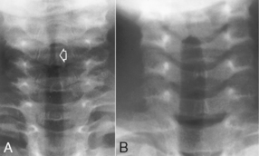
Position:
• To visualize neck region, include EAM at upper border of image.
• If distal larynx and trachea is of primary interest, center lower to include area from C3 to T5 (Fig. 1-18).
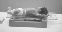
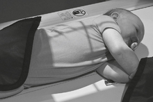
AP Pediatric Chest*

• 18 × 24 cm or 24 × 30 cm C.W. (8 × 10″ or 10 × 12″)
• TT (tabletop; nongrid). Grid with systems when it can’t be removed.
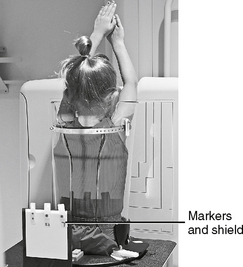
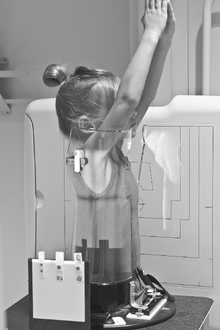
Erect PA Pediatric Chest (with Pigg-O-Stat)*

• 18 × 24 cm or 24 × 30 cm C.W. (8 × 10″ or 10 × 12″)
• IR (nongrid) or grid with systems when it can’t be removed
Position
• Patient on seat, legs through openings
• Adjust height of seat to place shoulders ≈1″ (2.5 cm) below upper margin of IR.
• Raise arms, and gently but firmly place side body clamps to hold raised arms and head in place.
• Set upper border of lead shield with R and L markers 1-2″ (2.5-5 cm) above level of iliac crest.
Lateral Pediatric Chest*

• 18 × 24 cm or 24 × 30 cm L.W. (8 × 10″ or 10 × 12″)
• TT (tabletop, nongrid) or grid with systems when it can’t be removed
Erect Lateral Pediatric Chest (with Pigg-O-Stat)*

• 18 × 24 cm or 24 × 30 cm L.W. (8 × 10″ or 10 × 12″)
• IR (nongrid) or grid with systems when it can’t be removed
PA (AP) Pediatric Chest
*Bontrager Textbook, 8th ed, pp. 83 and 84.
*Bontrager Textbook, 8th ed, pp. 79 and 85.
*Bontrager Textbook, 8th ed, p. 90.
*Bontrager Textbook, 8th ed, p. 92.
*Bontrager Textbook, 8th ed, p. 93.
*Bontrager Textbook, 8th ed, p. 95.
*Bontrager Textbook, 8th ed, p. 96.
*Bontrager Textbook, 8th ed, p. 97.
*Bontrager Textbook, 8th ed, pp. 100 and 101.
*Bontrager Textbook, 8th ed, p. 631.
*Bontrager Textbook, 8th ed, p. 632.
*Bontrager Textbook, 8th ed, p. 633.
*Bontrager Textbook, 8th ed, p. 634.