Upper Limb (Extremity)
• Technical factors and radiation protection
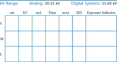
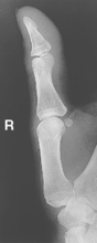
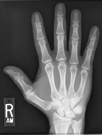
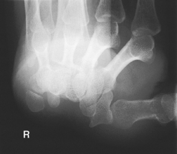
 AP axial thumb and PA hand critique
PA oblique hand and “fan” lateral hand critique
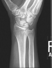
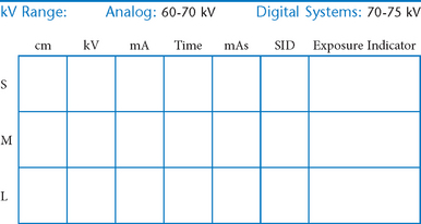
PA axial ulnar deviation (15° and Modified Stecher) (S)
Scaphoid projections (15° and Modified Stecher) critique
PA wrist radial deviation critique
Upper Limb (Extremity)*
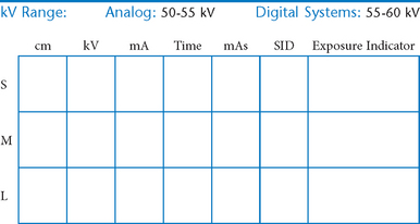
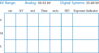
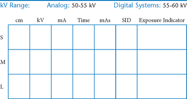
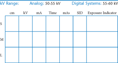
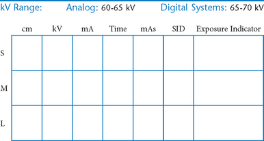
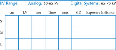
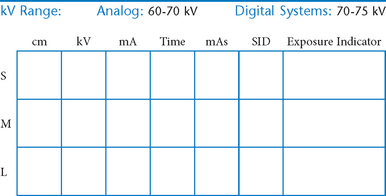
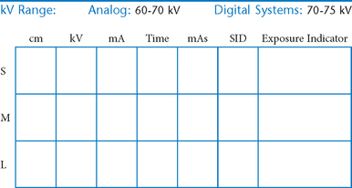
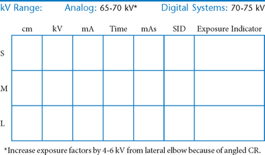
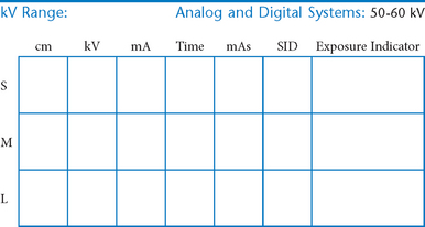
The following technical factors are important for all upper limb procedures to maximize image sharpness.
• 40-44″ (102-113 cm) SID, minimum OID
• Nongrid or TT (tabletop), detail (analog) screens
• Digital imaging requires special attention to accurate CR and part centering and close collimation.
• Immobilization (when needed)
• Multiple exposures per imaging plate: Multiple images can be placed on the same IP. When doing so, careful collimation and lead masking must be used to prevent pre-exposure or fogging of other images.
• Grid use with digital systems: Grids generally are not used with analog (film-screen) imaging for body parts measuring 10 cm or less. However, with certain digital systems, the grid may or may not be able to be removed from the receptor. In those cases, it is departmental protocol that determines if a grid is left in place or removed. Important: If a grid is used, the anatomy must be centered to it to avoid grid cutoff.
Radiation Protection
Close collimation is the most effective practice for preventing unnecessary radiation exposure to the patient.
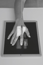
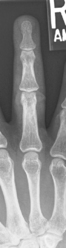
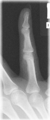
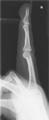
PA Fingers*

Alternative routine: Include entire hand on PA finger projection for possible secondary trauma to other parts of hand (see PA Hand).
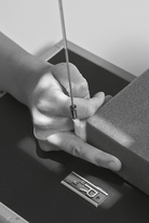
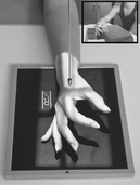
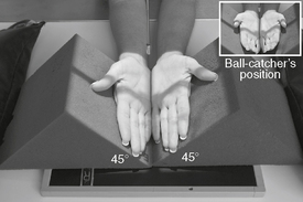
PA Oblique Fingers*

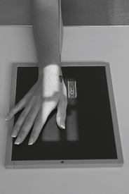
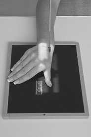
Position
• Patient seated, hand on table, elbow flexed 90° (lead shield over lap)
• Align fingers to long axis of portion of IR being exposed.
• Rotate hand 45° medially or laterally (dependent of digit examined), resting against 45° angle support block.
• Separate fingers; ensure that affected finger(s) is (are) parallel to IR.


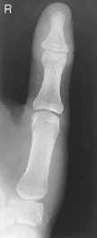
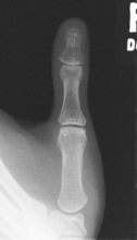
Lateral Fingers*

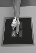

AP Thumb*


PA Oblique Thumb*


Lateral Thumb*

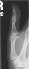
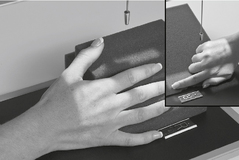
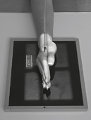
AP Axial Thumb*

Note: This is a special projection to better demonstrate the first carpometacarpal joint region.
Position
• Patient seated or standing, hand rotated internally placing posterior surface of thumb directly on IR
• Align thumb to long axis of portion of IR being exposed.
• Extend fingers and hold back with other hand to prevent superimposing base of thumb and 1st CMC joint region (a key positioning requirement).
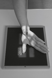
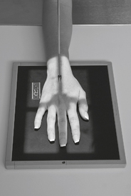
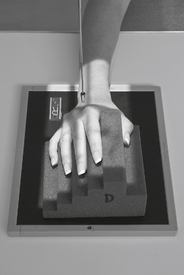
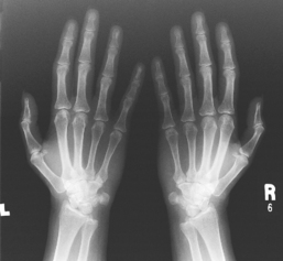
PA Hand*

PA Oblique Hand*

Lateral Hand (Fan and Extension Lateral)*


AP Oblique Bilateral Hand*


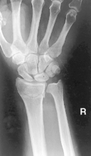
PA Wrist*

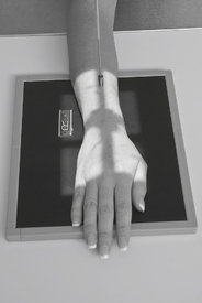

PA Oblique Wrist*

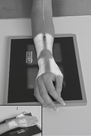

Lateral Wrist*

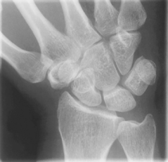
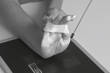
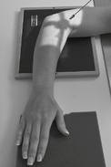
PA Axial Wrist—UInar Deviation and Modified Stecher (Scaphoid)*

Warning: The ulnar deviation view should be attempted only with possible wrist trauma after a routine wrist series rules out gross fractures to wrist or distal forearm. PA axial projection recommended for obscure fractures. If patient can’t ulnar deviate wrist, elevate hand on 20° angle sponge.
Note: See p. 26, 8th ed textbook for joint movement terminology.
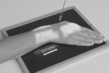
PA Axial Scaphoid (Ulnar Deviation with 15° and Modified Stecher)
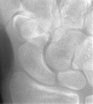
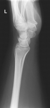
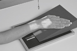
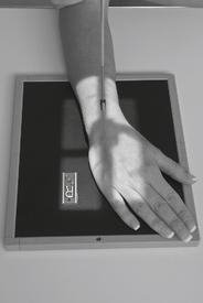
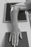
PA Wrist—Radial Deviation*

Warning: This position should be attempted for possible wrist trauma only after a routine wrist series rules out gross fractures to wrist or distal forearm.
Note: See p. 26, 8th ed textbook, for explanation on wrist joint movement terminology.

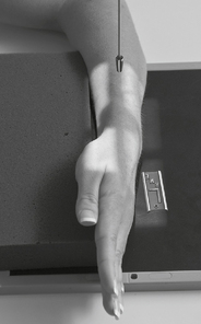
Wrist—Carpal Canal*
(Gaynor-Hart Tangential Projection)

Warning: This position is sometimes called the “tunnel view” and should be attempted for possible wrist trauma only after a routine wrist series rules out gross fractures to wrist or distal forearm.
Position
• Patient seated, hand on table (shield across lap)
• Hyperextend (dorsiflex) wrist as far as patient can tolerate with patient using other hand to hold fingers back.
• Rotate hand and wrist slightly internally—toward radius (≈5°–10°).

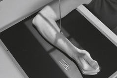
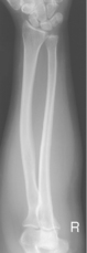
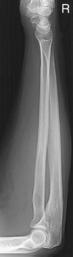
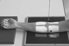
AP Forearm*

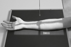

Lateral Forearm*

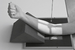
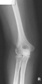
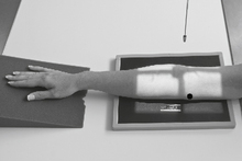
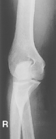
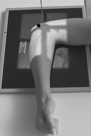
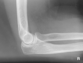
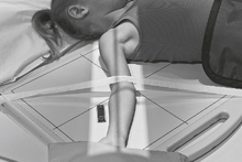
AP Elbow*
Position
• Elbow extended and hand supinated (shield across lap)
• Lean laterally as needed for true AP (palpate epicondyles)
• If elbow cannot be fully extended, take two AP projections as shown (Figs. 2-44 and 2-45) with CR perpendicular to distal humerus on one, and perpendicular to proximal forearm on another.
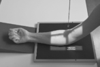
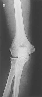
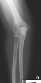
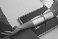
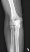
Oblique Elbow (Medial and Lateral Rotation)*

Medial (internal) oblique best visualizes coronoid process. Lateral (external) oblique best visualizes radial head and neck (most common oblique projection).
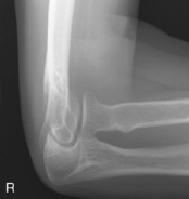
Lateral Elbow*

Lateral Elbow
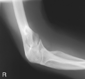
Trauma Axial Lateral Elbow*

Trauma Axial Lateral Elbow
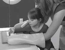
Pediatric AP Upper Limb*

With possible trauma, handle limb very gently with minimal movement. Take a single exposure to rule out gross fractures before additional radiographs are taken.
Position
• Supine position, arm abducted away from body, lead shield over pelvic area
• Include entire limb unless a specific joint or bone is indicated.
• Immobilize with clear flexible-type retention band and sandbags, or with tape.
• Use parental assistance only if necessary, provide lead gloves and apron.

Pediatric Lateral Upper Limb*

Position
• Supine position with arm abducted away from body, lead shield over pelvic area
• Include entire limb unless a specific joint or bone is indicated.
• Immobilize with clear flexible-type retention band and sandbags or with tape.
• Flex elbow and rotate entire arm into a lateral position.
• Use parental assistance only if necessary, provide lead gloves and apron.
*Bontrager Textbook, 8th ed, pp. 136 and 137.
*Bontrager Textbook, 8th ed, p. 141.
*Bontrager Textbook, 8th ed, p. 142.
*Bontrager Textbook, 8th ed, p. 143.
*Bontrager Textbook, 8th ed, p. 144.
*Bontrager Textbook, 8th ed, p. 145.
*Bontrager Textbook, 8th ed, p. 146.
*Bontrager Textbook, 8th ed, p. 147.
*Bontrager Textbook, 8th ed, p. 149.
*Bontrager Textbook, 8th ed, p. 150.
*Bontrager Textbook, 8th ed, p. 151.
*Bontrager Textbook, 8th ed, p. 153.
*Bontrager Textbook, 8th ed, p. 154.
*Bontrager Textbook, 8th ed, p. 155.
*Bontrager Textbook, 8th ed, p. 156.
*Bontrager Textbook, 8th ed, pp. 157 and 158.
*Bontrager Textbook, 8th ed, p. 159.
*Bontrager Textbook, 8th ed, p. 160.
*Bontrager Textbook, 8th ed, p. 162.
*Bontrager Textbook, 8th ed, p. 163.
*Bontrager Textbook, 8th ed, pp. 164 and 165.
*Bontrager Textbook, 8th ed, pp. 166 and 167.
*Bontrager Textbook, 8th ed, p. 168.
*Bontrager Textbook, 8th ed, p. 170.
*Bontrager Textbook, 8th ed, p. 635.
*Bontrager Textbook, 8th ed, p. 635.