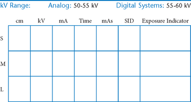
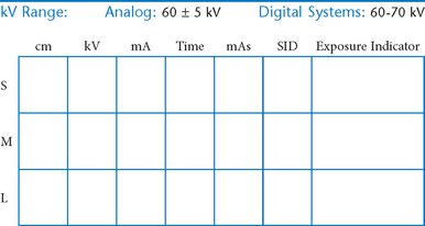
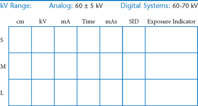
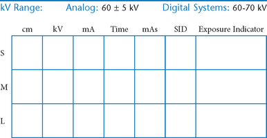
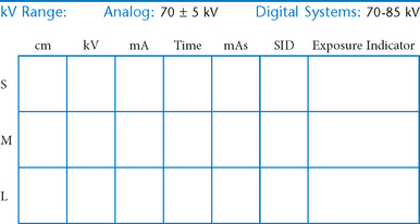
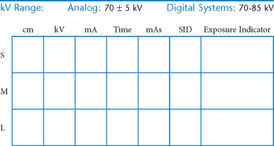
Lower Limb (Extremity)
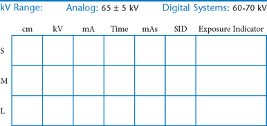
• Technical considerations and radiation protection
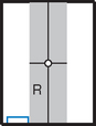
 AP oblique (medial and lateral rotation) (R)
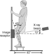
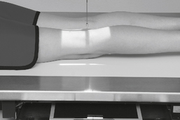
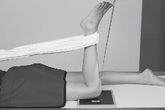
PA axial weight-bearing (Rosenberg method) (S)
PA axial weight-bearing critique
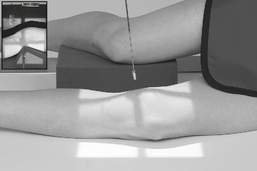
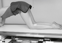
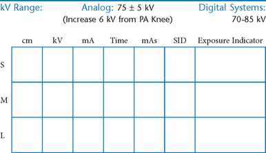
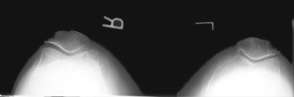
Intercondylar fossa (tunnel view), Camp Coventry and Holmblad (S)
Lower Limb (Extremity)
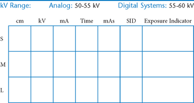
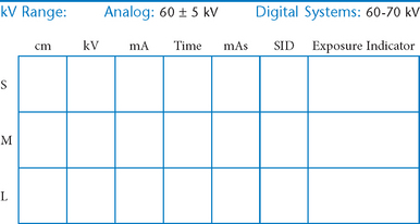
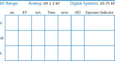
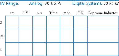
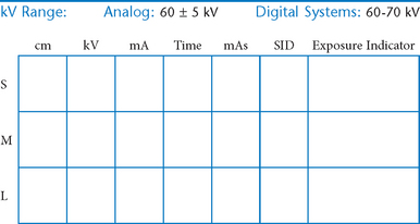
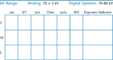
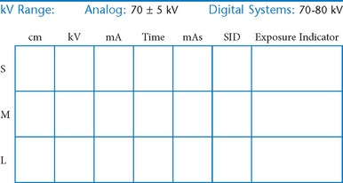
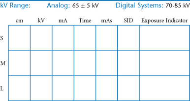
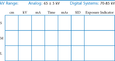
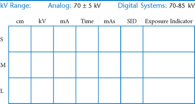
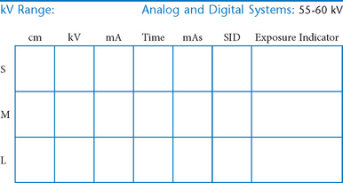
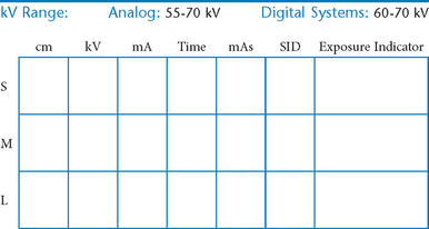
Digital Imaging Considerations
• Four-sided collimation: Collimate to the area of interest with a minimum of two collimation parallel borders clearly demonstrated on the image. Four-sided collimation is always preferred if study allows it.
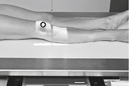
• Accurate centering: It is important that the body part and the central ray be centered to the IR.
• Grid use with cassette-less systems: Anatomy thickness and kV range are deciding factors for whether a grid is to be used. With cassette-less systems it may be impractical and difficult to remove the grid. Therefore, the grid is commonly left in place even for smaller body parts measuring 10 cm or less. If the grid is left in place, it is important to ensure that the CR is centered to the grid for all projections.
Collimation and Shielding
A general rule for protective shielding states that it should be used whenever radiation-sensitive areas lie within or near the primary beam. Red bone marrow and gonadal tissues are two of the key radiation-sensitive regions. However, a good practice to follow, in addition to close collimation to the area of interest, is to use gonadal shields on youth and patients of childbearing age for all lower limb procedures. This provides assurance to the patient that he or she is being protected from unnecessary exposure.
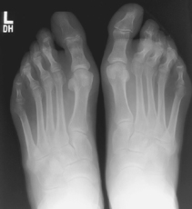
AP Toes*

Alternative routine may include entire foot on AP toe projection for possible secondary trauma to other parts of foot (see AP foot).
AP Oblique Toes*


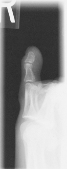
Lateral Toes*

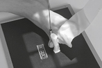
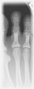
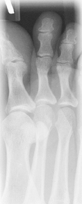
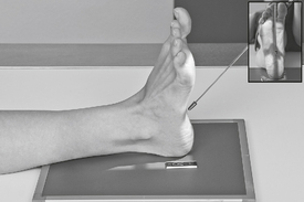
Toes—Sesamoids*

Position
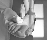
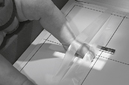
• Patient prone with foot and great toe carefully dorsiflexed so the plantar surface forms a 15°–20° angle from vertical if possible (adjust CR angle as needed)
Alternative Supine Position:
This may be a more tolerable position for patient to maintain if in great pain.

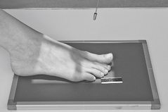
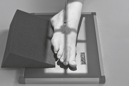
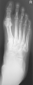
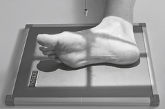
AP Foot*

Position
• Supine or seated with plantar surface of foot flat on IR, aligned lengthwise to portion of IR being exposed
• Extend (plantar flex) foot by sliding foot and IR distally while keeping plantar surface flat on IR. (Support with sandbags to keep foot and IR from sliding farther.)
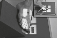
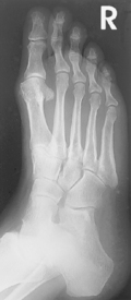
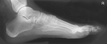
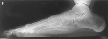
AP Oblique Foot*

Position
• Supine or seated with foot centered lengthwise to portion of IR being exposed
• Oblique foot 30°–40° medially, support with 45° radiolucent angle block and sandbags to prevent slippage
• Note 1: A higher arch requires nearer 45° oblique and a low arch “flat foot” nearer 30°.
• Note 2: A 30° lateral oblique projection will demonstrate the space between 1st and 2nd metatarsals and between 1st and 2nd cuneiforms.
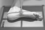
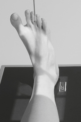
Lateral Foot*

Position (Mediolateral)
• Recumbent, turned on affected side, knee flexed with unaffected leg behind to prevent overrotation
• Place support under affected knee and leg as needed to place plantar surface of foot perpendicular to IR for a true lateral.
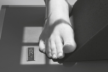
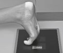
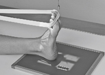
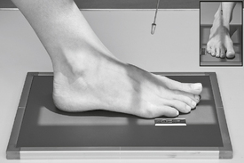
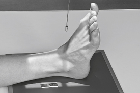
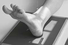
Weight-Bearing Feet AP and Lateral*

Lateral projection is most common for longitudinal arch (flat feet), AP demonstrates alignment of metatarsals and phalanges.
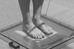
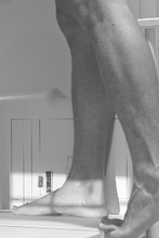
Weight-Bearing AP and Lateral Foot
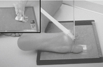
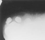
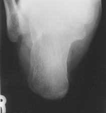
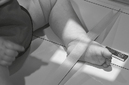
Plantodorsal Calcaneus*

Position
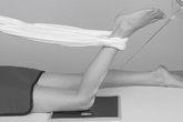
• Supine or seated, dorsiflex foot to as near vertical position as possible. If possible, have patient pull on gauze as shown. (This may be painful for patient to maintain, don’t delay!)
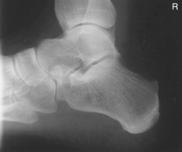
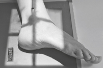
Lateral Calcaneus*

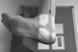
Plantodorsal (Axial) and Lateral Calcaneus
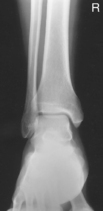
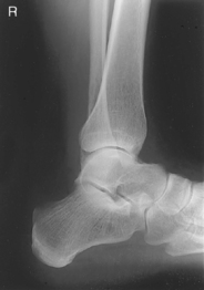
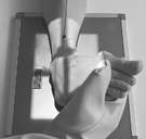
AP Ankle*

AP Mortise Ankle*

This is a frontal view of the entire ankle mortise and generally should not be a substitute for the routine AP or 45° oblique ankle.
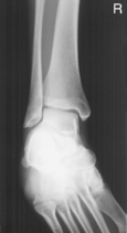
AP Oblique Ankle*


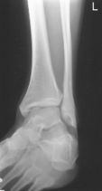
Lateral Ankle*

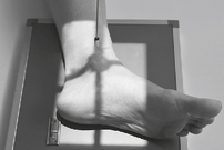
Position
• Recumbent, affected side down, affected knee partially flexed
• Dorsiflex foot 90° to leg if patient can tolerate.
• Place support under knee as needed for true lateral of foot and ankle.
AP Ankle—Stress Views*
(Inversion and Eversion Positions)

Warning: Stress must be applied very carefully, either by a long gauze held by patient or handheld by qualified person wearing lead gloves and apron (may require injection of local anesthetic by a physician).

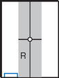
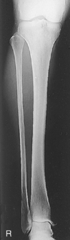
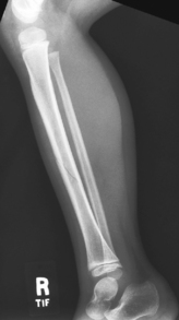
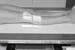
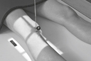
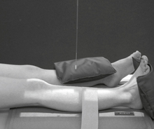
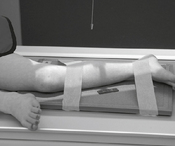
AP Leg (Tibia-Fibula)*
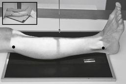
Lateral Leg (Tibia-Fibula)*
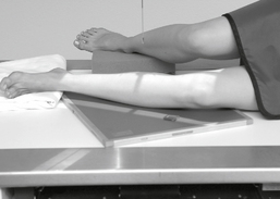
Position
• Recumbent, affected side down
• Place unaffected limb behind patient to prevent over-rotation.
• Place support under distal portion of affected foot as needed to ensure a true lateral position of foot, ankle, and knee.
• Include ≈3 cm (1-1.5″) minimum beyond knee and ankle joints considering divergent rays
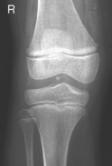
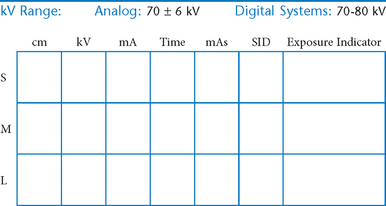
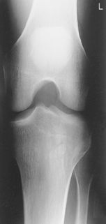
AP Knee*

Position
• Supine, or seated on table, with leg extended and centered to CR and midline of table or IR
• Rotate leg slightly inward as needed to place knee and leg into a true AP. Center IR to CR.
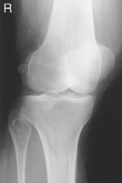
AP Oblique Knee*

Medial oblique: Demonstrates fibular head and neck unobscured. (Lateral oblique may also be taken.)

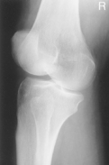
Lateral Knee*

Lateral Knee
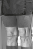
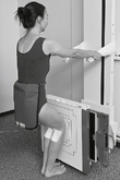
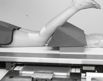
Knees—AP or PA Weight-Bearing*


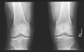
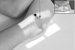
Knee for Intercondylar Fossa*

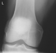
PA Patella*

Position
• Prone, knee centered to CR and midline of table or IR
• If patella area is painful, place pad under thigh and leg to prevent direct pressure on patella.
• Rotate anterior knee approximately 5° internally or as needed to place an imaginary line between the epicondyles parallel to the plane of the IR.
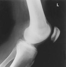
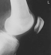
Lateral Patella*

Intercondylar Fossa, PA and Lateral Patella
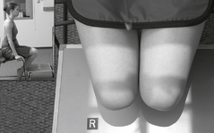
Patella—Tangential Projection*

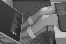
Position
• Supine with knees flexed 45° on leg supports (important for patient to be comfortable with legs totally relaxed to prevent patellae from being drawn into intercondylar sulcus)
• Place IR on supports against legs about 30 cm (12″) distal to patellae, perpendicular to CR.
• Internally rotate both legs as needed to center patellae to midfemora.
Patella—Tangential Projection*


Pediatric AP Lower Limb*

Pediatric Lateral Lower Limb*

Position—Shield Gonads
• Semisupine, include entire limb, shield over pelvic area
• Immobilize arms and unaffected leg with sandbags as needed
• Abduct (frog leg) affected limb into lateral position, immobilize with tape or compression band. (Do not attempt with hip trauma or hip disease.)
• If parental assistance is necessary, provide lead gloves and apron

Pediatric—AP and Lateral Foot*

*Bontrager Textbook, 8th ed, p. 226.
*Bontrager Textbook, 8th ed, p. 227.
*Bontrager Textbook, 8th ed, p. 228.
*Bontrager Textbook, 8th ed, p. 229.
*Bontrager Textbook, 8th ed, p. 230.
*Bontrager Textbook, 8th ed, p. 231.
*Bontrager Textbook, 8th ed, p. 232.
*Bontrager Textbook, 8th ed, pp. 233 and 234.
*Bontrager Textbook, 8th ed, p. 235.
*Bontrager Textbook, 8th ed, p. 236.
*Bontrager Textbook, 8th ed, p. 237.
*Bontrager Textbook, 8th ed, p. 238.
*Bontrager Textbook, 8th ed, p. 239.
*Bontrager Textbook, 8th ed, p. 240.
*Bontrager Textbook, 8th ed, p. 241.
*Bontrager Textbook, 8th ed, p. 242.
*Bontrager Textbook, 8th ed, p. 243.
*Bontrager Textbook, 8th ed, p. 244.
*Bontrager Textbook, 8th ed, pp. 245 and 246.
*Bontrager Textbook, 8th ed, p. 247.
*Bontrager Textbook, 8th ed, p. 248.
*Bontrager Textbook, 8th ed, p. 249.
*Bontrager Textbook, 8th ed, pp. 251 and 252.
*Bontrager Textbook, 8th ed, p. 254.
*Bontrager Textbook, 8th ed, p. 255.
*Bontrager Textbook, 8th ed, p. 256.
*Bontrager Textbook, 8th ed, pp. 257 and 258.
*Bontrager Textbook, 8th ed, p. 258.
*Bontrager Textbook, 8th ed, p. 637.
*Bontrager Textbook, 8th ed, p. 637.
*Bontrager Textbook, 8th ed, p. 638.