Femur and Pelvic Girdle
 AP (R)
Femur and Pelvic Girdle
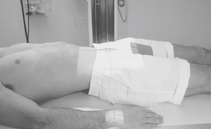
Male:
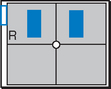
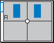
Gonadal shields should be used on pelvis and hip procedures for all male children and adults of childbearing age. Contact shields should be placed over the testes with the upper edge of the shield placed at the inferior margin of the symphysis pubis.

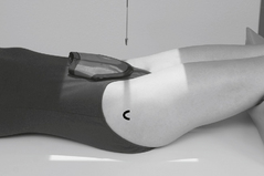
Female:
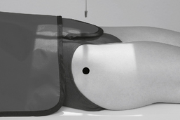
For AP and “frog-leg” laterals of the hips, specially shaped ovarian shields can be carefully placed over the area of the ovaries without obscuring essential anatomy as shown. This should be done on all female children and adults of childbearing age. These ovarian shields, however, may obscure essential anatomy on certain pelvic examinations. Departmental policy regarding shielding and kV range to be used should be determined.
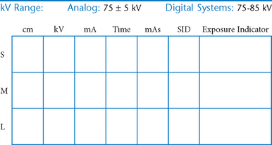
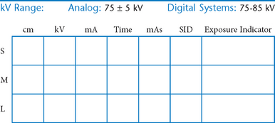
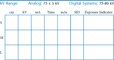
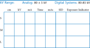
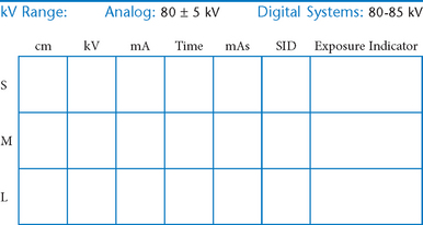
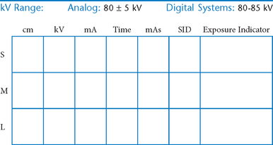
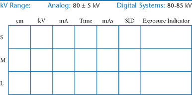
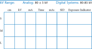
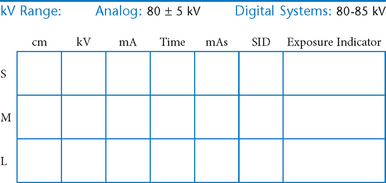
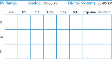
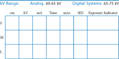
kV Range:
A higher kV range (90 ± 5) with lower mAs may be used for examinations of the hips and pelvis of adults to reduce the total radiation dose to the patient.
Close collimation to the area of interest is important for all procedures, including the hips and pelvis, even with gonadal shields. (See Appendix A for further explanation.)
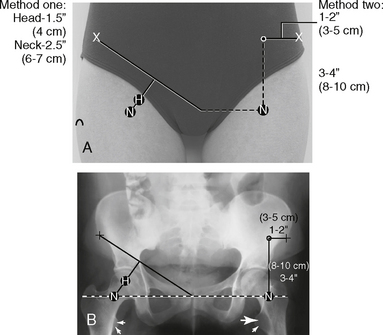
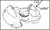
Location of Femoral Head and Neck
First Method:
Location of the femoral head and neck regions can be accurately determined by first drawing an imaginary line between two landmarks, the ASIS and the symphysis pubis. The midpoint of this line is determined, from which a perpendicular imaginary line is drawn to locate the head and/or neck. The femoral head (A) is approximately 1.5″ (4 cm) down on this line. The midfemoral neck (B) is approximately 2.5″ (6-7 cm) down, as shown in the photo below.
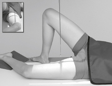
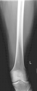
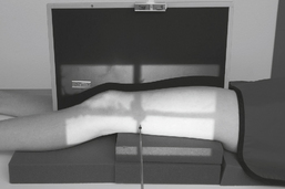
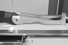
AP Femur*
Note: For adults, a second smaller IR of either the hip or the knee should be taken on trauma patients to demonstrate both knee and hip joints to rule out possible fractures.
Position
• Supine, femur centered to midline of table or grid IR
• Rotate entire lower limb internally ≈5° for AP of midfemur and distal femur, and 15° internally for true AP to include hip.
• Lower border of IR ≈5 cm (2″) below knee to include knee joint adequately (see AP Unilateral Hip for proximal femur, p. 156).
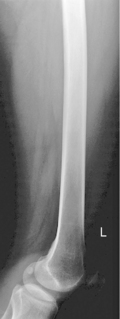
Lateral Femur*
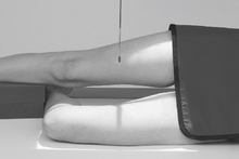
Warning: Take horizontal beam lateral if fracture is suspected.
Note: For adults, take a second smaller IR of lateral hip or lateral knee if both joints are areas of interest.

Horizontal Beam Lateral Femur*
(Trauma Midfemur and Distal Femur)
Note: For proximal femur injuries, take axiolateral (Danelius-Miller method) hip.
AP Bilateral Hips*
Warning: Do not attempt to rotate leg if fracture is suspected. Take “as is” bilateral hips for comparison purposes.
Note: For AP pelvis centering, see p. 291 in text.
Position
• Supine, aligned and centered to CR and IR, both legs extended and equally rotated internally 15°-20° (see warning above)
• Ensure no rotation of pelvis (bilateral ASISs the same distances from tabletop). Support under knees for patient comfort.
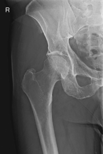
AP Unilateral Hip*

Warning: For possible fractured hip, take AP bilateral hips (preceding page) for comparison purposes.
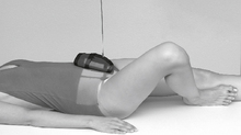
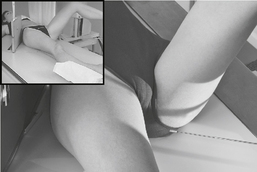
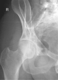
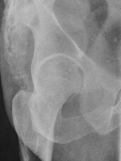
Lateral Hip (Nontrauma)*

Warning: Do not attempt with possible fracture of hip area.
Position
• For femoral neck, flex affected knee and hip, and abduct femur 45° from vertical (places femoral neck near parallel to IR).
• For femoral head, acetabulum, and proximal femoral shaft, oblique patient 35°–45° toward affected side and abduct leg to tabletop if possible. Center hip and neck area to CR.

Lateral Hips (Nontrauma)*

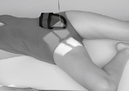
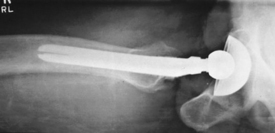
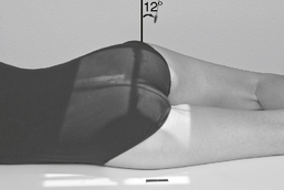
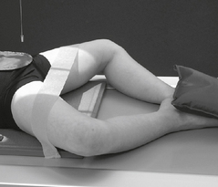
Lateral Hip (Trauma Method)*
(Axiolateral Inferosuperior Projection [Danelius-Miller Method])

Position
• Supine, no rotation of pelvis
• Flex unaffected knee and hip and provide support such as the x-ray tube (use pad or towels for possible hot collimator).
• Rotate affected leg internally 15° unless possible hip fracture.
• Place vertical grid IR against side just superior to iliac crest with plane of IR perpendicular to CR.
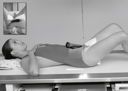
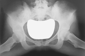
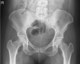
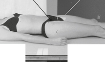
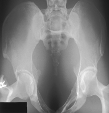
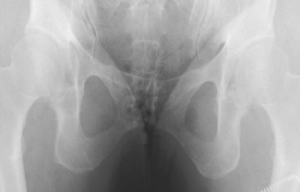
AP Pelvis*
To include proximal femora, pelvic girdle, sacrum, and coccyx
Warning: Do not attempt to rotate legs if fractures involving hips are suspected.
Note: For bilateral hips centering, see p. 291.
Position
• Supine, pelvis centered to centerline, legs extended
• Both feet, knees, and legs equally rotated internally 15° (secure with tape if necessary). Support under knees for comfort.
• Ensure no rotation of pelvis (ASISs equal distance from TT).
• Center IR to CR. (Include entire pelvis.) Shield gonads (if it doesn’t compromise study).
AP Pelvis
AP Axial Pelvis*


AP Axial Pelvis
Acetabulum—Posterior Oblique Pelvis*

Note: Both sides generally are taken for comparison, either both for upside or both for downside.
• 24 × 30 cm L.W. (10 × 12″) or 35 × 43 cm C.W. (14 × 17″) if both hips must be seen on each projection.
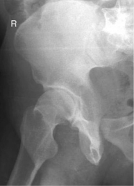
Acetabulum*

Pediatric AP and Lateral Hips*

Warning: Do not attempt “frog-leg” lat. with possible hip pathology unless so indicated by a physician after review of AP pelvis radiograph.
Position (AP and Lateral)
• Supine, pelvis centered to CR and to IR; use gonadal shields on both male and female. (Use ovarian shield of appropriate size for female, ensuring that it does not cover hip areas.)
• Immobilize arms and upper body with sandbags, tape, or compression band as needed.
*Bontrager Textbook, 8th ed, p. 274.
*Bontrager Textbook, 8th ed, p. 276.
*Bontrager Textbook, 8th ed, p. 275.
*Bontrager Textbook, 8th ed, p. 277.
*Bontrager Textbook, 8th ed, p. 283.
*Bontrager Textbook, 8th ed, p. 285.
*Bontrager Textbook, 8th ed, p. 278.
*Bontrager Textbook, 8th ed, p. 284.
*Bontrager Textbook, 8th ed, p. 277.
*Bontrager Textbook, 8th ed, pp. 279 and 280.
*Bontrager Textbook, 8th ed, p. 281.
*Bontrager Textbook, 8th ed, p. 282.
*Bontrager Textbook, 8th ed, p. 639.