Vertebral Column
• Intervertebral foramina and zygapophyseal joints
 AP (PA) dens (Fuchs and Judd methods) (S)
AP open mouth and AP (PA) dens critique
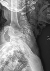
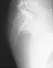
Lateral cervicothoracic (swimmer’s) (R)
Lateral and swimmer’s critique
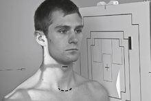
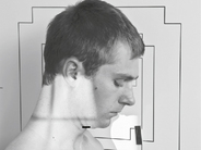
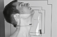
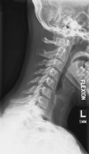
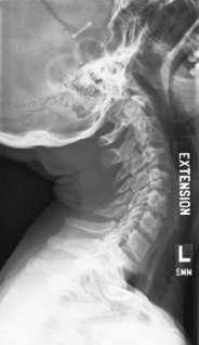
Lateral hyperflexion and hyperextension (S)
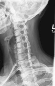
Hyperflexion and hyperextension critique
Trauma series: horizontal beam lateral, AP axial, obliques, cervicothoracic lateral (S)
Lateral and lateral L5-S1 critique
Scoliosis series (Ferguson method) (S)
Intervertebral Foramina and Zygapophyseal Joints
Certain lateral and oblique projections best demonstrate these important foramina and joints of the spine as follows:
| Zygapophyseal Joints | Intervertebral Foramina | |
| Cervical spine | Lateral position | 45° anterior oblique (side closest to IR) |
| Thoracic spine | 70° anterior oblique (side closest to IR) | Lateral position |
| Lumbar spine | 45° posterior oblique (side closest to IR) | Lateral position |
AP for C1-C2*

Position

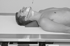
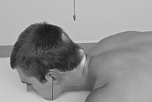
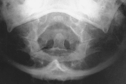
AP for Dens (Odontoid Process)*
(AP Fuchs Method [and PA Judd Method])
Warning: Do not attempt on possible cervical trauma.

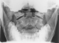
AP Open Mouth and AP (PA) Dens

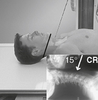
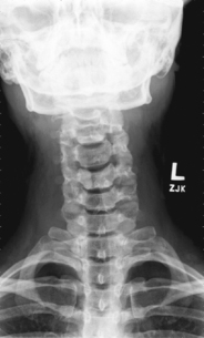
AP Axial Cervical Spine*

Oblique Projections, Cervical Spine*

Right and left obliques taken for comparison (as either posterior or anterior obli’s); anterior obli’s result in less thyroid dose.
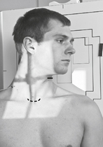
Position
• Erect preferred (sitting or standing), entire torso and head turned 45° to IR, C spine aligned to CR (and centerline of IR)
• Raise chin slightly, looking straight ahead (or turn head slightly toward IR to prevent superimposing C1 by mandible).
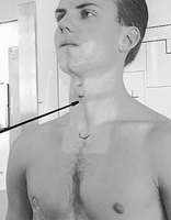
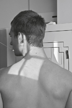
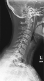
Lateral Cervical Spine*

Position
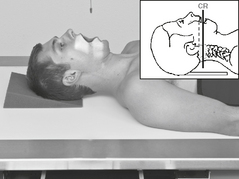
• Erect (sitting or standing) in lateral position, C spine aligned and centered to CR (and centerline of IR)
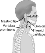
• Top of IR ≈1-2″ (3-5 cm) above level of EAM
• Raise chin slightly (to remove mandible angles from spine).
• Relax and depress both shoulders evenly (weights in each hand may be necessary to visualize C7).

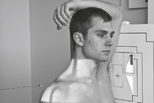
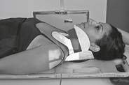
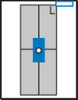
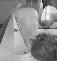
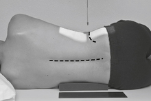
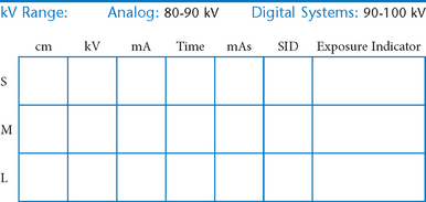
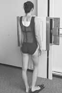
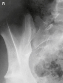
Lateral Cervicothoracic Spine*
Swimmer’s (Twining Method) C5-T3 Region

Position
• Erect preferred, align C-spine to CR (and centerline of IR).
• Elevate arm and shoulder closest to IR and rotate this shoulder slightly anteriorly or posteriorly.
• Opposite arm down, relax and depress shoulder, with slight opposite rotation (from other shoulder) to separate humeral heads from vertebra. May also be taken in lateral recumbent position with one arm and shoulder down and one up—Pawlow method.

Erect Lateral and Cervicothoracic (Swimmer’s) Lateral
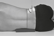
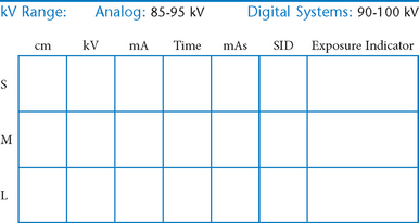
Lateral Cervical Spine Hyperflexion—Hyperextension*


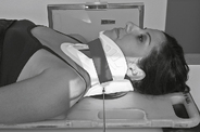
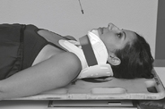
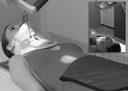
Cervical Spine—Trauma Series*
Warning: Do not remove cervical collar unless so indicated by the physician after viewing horizontal beam lateral.
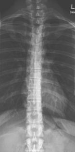
AP Thoracic Spine*
• Feet at cathode end (anode heel effect)
• Wedge compensation filter recommended to produce uniform density of spine
Position
• Supine, spine aligned and centered to centerline, flex hips and knees to reduce lordotic curvature
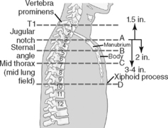
• Top of IR 1.5″ (3 cm) above shoulder
• Ensure no rotation of thorax or pelvis. Shield radiosensitive tissues.

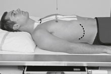
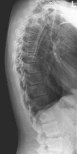
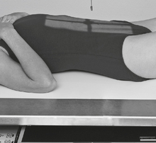
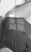
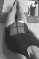
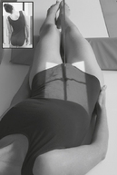
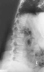
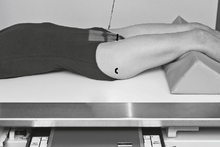
Lateral Thoracic Spine*
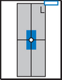
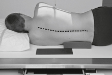
Position
• Recumbent, support under head, lateral with hips and knees flexed, arms raised and elbows flexed. Shield radiosensitive tissues.
• Align and center midaxillary plane to centerline
• Top of IR 1.5″ (3 cm) above shoulders; no rotation
• Supports should be placed under lower back as needed to straighten and align spine near parallel to tabletop. (A slight natural curvature corresponding to divergent rays is helpful.)

Oblique Thoracic Spine*
Both oblique projections generally taken for comparison. May also take as anterior obliques (lower breast dose).
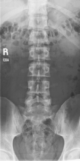
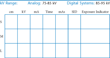
AP (PA) Lumbar Spine*
Note: May be taken PA for better opening of intervertebral spaces by divergent rays.
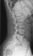
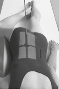
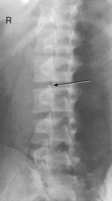
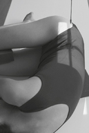
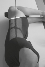
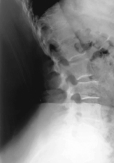
Lateral Lumbar Spine*
Position
• Recumbent in true lateral position, flex hips and knees, align and center midaxillary plane to centerline
• Place support under waist as needed to place entire spine parallel to tabletop (see Note). Provide support between knees.
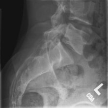
Lateral L5-S1, Lumbar Spine*

Oblique Lumbar Spine*

Both oblique projections generally taken for comparison (as either anterior or posterior obliques).
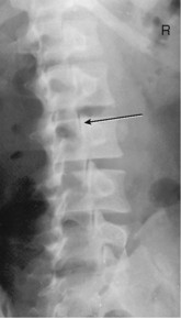
Scoliosis Series*

PA greatly reduces breast dose.
• 35 × 43 cm L.W. (14 × 17″) or 35 × 92 cm (14 × 36″)
• Compensating filters to produce a more uniform density of spine
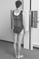
Position
First IR:
Erect, standing or seated, spine aligned and centered to centerline, arms at side, no rotation of pelvis or thorax
Lumbar Spine*
AP (PA) Right and Left Bending
Note: May be taken erect PA to reduce breast dose.
• 35 × 43 cm (14 × 17″), L.W., or 35 × 92 cm (14 × 36″)
• Compensating filters to produce a more uniform density of spine

Lumbar Spine*
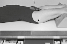
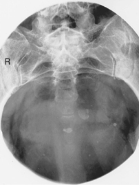
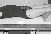
AP Axial Sacrum*

AP Axial Coccyx*

Note: May be done PA with 10° cephalic angle if patient cannot sustain weight on the coccyx area in a supine position.
Urinary bladder should be emptied before procedure is performed.

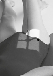
Lateral Sacrum (and Coccyx)*

Note: Lateral sacrum and lateral coccyx may be taken as one projection if both sacrum and coccyx are being examined (reduces patient exposure).
Lateral Coccyx*

Note: Lateral sacrum and lateral coccyx are commonly taken as one projection if both sacrum and coccyx are being examined (reduces patient exposure).
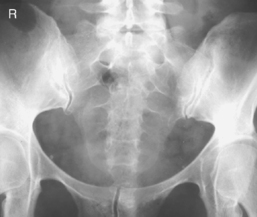
Sacroiliac Joints*

Sacroiliac Joints*


*Bontrager Textbook, 8th ed, p. 308.
*Bontrager Textbook, 8th ed, p. 315.
*Bontrager Textbook, 8th ed, p. 309.
*Bontrager Textbook, 8th ed, p. 310.
*Bontrager Textbook, 8th ed, p. 311.
*Bontrager Textbook, 8th ed, p. 313.
*Bontrager Textbook, 8th ed, p. 314.
*Bontrager Textbook, 8th ed, pp. 591 and 592.
*Bontrager Textbook, 8th ed, p. 318.
*Bontrager Textbook, 8th ed, p. 319.
*Bontrager Textbook, 8th ed, p. 320.
*Bontrager Textbook, 8th ed, p. 335.
*Bontrager Textbook, 8th ed, p. 337.
*Bontrager Textbook, 8th ed, p. 338.
*Bontrager Textbook, 8th ed, p. 336.
*Bontrager Textbook, 8th ed, p. 340.
*Bontrager Textbook, 8th ed, p. 343.
*Bontrager Textbook, 8th ed, p. 344.
*Bontrager Textbook, 8th ed, p. 345.
*Bontrager Textbook, 8th ed, p. 346.
*Bontrager Textbook, 8th ed, p. 347.
*Bontrager Textbook, 8th ed, p. 348.
*Bontrager Textbook, 8th ed, p. 349.
*Bontrager Textbook, 8th ed, p. 350.