Chapter 7

Bony Thorax

Bony Thorax—Positioning Considerations

Sternum

The routine for a sternum generally includes a lateral and an oblique wherein the sternum is shifted to the left of the spine and is superimposed over the homogeneous heart shadow. A 15°–20° RAO achieves this best. An orthostatic-breathing technique generally is used to blur out the lung markings and the ribs overlying the sternum. If preferred, exposure can also be made on suspended expiration.

Ribs

Each technologist should determine the preferred routine for his or her department.

Two-Image Routine

One suggested two-image routine is an AP or PA with the area of injury closest to the image receptor (IR) (above or below diaphragm) and an oblique projection of the axillary ribs on the side of injury. Therefore the oblique for this routine on an injury to the left anterior ribs would be an RAO shifting the spine away from the area of injury and to increase visibility of the left axillary ribs. The oblique for an injury to the right posterior ribs would be an RPO wherein the spine again is rotated away from the area of injury.

Three-Image Routine

Another three-image routine required in some departments for all rib trauma consists of AP above diaphragm or AP below diaphragm and RPO and LPO of the site of injury.

Above and Below Diaphragm

The location of the injury site in relationship to the diaphragm is important for all routines. Those injuries above the diaphragm require less exposure (nearer to a chest technique) when taken on inspiration and those below the diaphragm require an exposure nearer to that of an abdomen technique when taken on expiration.

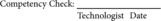
Right Anterior Oblique (RAO) Sternum*
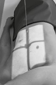
image

• 24 × 30 cm L.W. (10 × 12″)

• Grid

• Orthostatic-breathing technique or suspended expiration

• AEC not recommended

image

Fig. 7-1 Erect 15°–20° RAO sternum (insert: trauma option).

Position

• Erect (preferred) or semiprone, turned 15°–20° with right side down. (A thin-chested patient requires slightly more obliquity than a thick-chested patient.)

• Center sternum to CR at midline of table or IR holder

Central Ray:

CR ⊥, to midsternum (midway between jugular notch and xiphoid process)

SID:

40-44″ (102-113 cm)

Collimation:

Long, narrow collimation field to region of sternum

Respiration:

Orthostatic-breathing technique of 2-3 seconds or suspend upon expiration

image

Lateral Sternum*

image

• 24 × 30 cm L.W. (10 × 12″) or 30 × 35 cm (11 × 14″)

• Grid

• AEC not recommended

• Place lead blocker anterior to sternum (for recumbent position)

image

Fig. 7-2 Lateral, erect sternum (trauma option).

Position

• Erect (seated or standing), or recumbent lying on side with vertical CR; or supine with cross-table CR for severe trauma

• Draw shoulders and arms back.

• Align sternum to CR at midline of IR holder.

• Top of IR 1.5″ (4 cm) superior to level of jugular notch

Central Ray:

CR ⊥, to midsternum

SID:

60-72″ (153-183 cm)

Collimation:

Long, narrow collimation field to region of sternum

Respiration:

Expose upon full inspiration.

image

Oblique (RAO) Sternum

Evaluation Criteria

Anatomy Demonstrated:

• Entire sternum superimposed on heart shadow

Position:

• Correct rotation, sternum visualized alongside vertebral column

Exposure:

• 2- to 3-second exposure using breathing technique; lung markings appear blurred

• Optimal contrast and density (brightness) to visualize entire sternum

image

Fig. 7-3 RAO sternum.
image

Lateral Sternum

Anatomy Demonstrated:

• Entire sternum

Position:

• No rotation, sternum visualized with no superimposition on the ribs

• Shoulders and arms drawn back

image

Fig. 7-4 Lateral sternum.
image (From Frank ED, Long BW, Smith BJ: Merrill’s atlas of radiographic positioning and procedures, ed 12, St. Louis, 2012, Elsevier.)

Exposure:

• No motion, sharp bony margins

• Optimal contrast and density (brightness) to visualize entire sternum

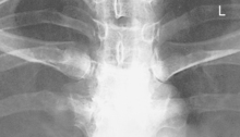
Sternoclavicular Joints PA and Anterior Oblique Projections*
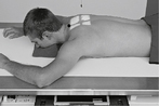
image

• 18 × 24 cm C.W. (8 × 10″)

• Grid

image

Fig. 7-5 Bilateral PA.

image

Fig. 7-6 RAO, 10°–15° oblique, CR ⊥ (both obliques commonly taken for comparison).

Position

PA:

Prone or erect, midsagittal plane to centerline of CR

• Turn head to side, no rotation of thorax

• Center IR to CR

Oblique:

Rotate thorax 10°–15° to shift vertebrae away from sternum (best visualizes downside SC joint). RAO will demonstrate the right SC joint. LAO will demonstrate the left SC joint.

Less obliquity (5°–10°) will best visualize the upside SC joint next to spine.

Central Ray:

• PA: Level of T2-T3. CR ⊥ to MSP and ≈7 cm (3″) distal to vertebra prominens (3 cm or 1.5″ inferior to jugular notch)

• Oblique: Level of T2-T3. CR ⊥, to ≈5 cm (2″) lateral to MSP (toward elevated side) and ≈7 cm (3″) distal to vertebra prominens

SID:

40-44″ (102-113 cm)

Collimation:

To region of sternoclavicular joints with four-sided collimation

Respiration:

Suspend respiration upon expiration.

image

Sternoclavicular (SC) Joints—PA

Evaluation Criteria

Anatomy Demonstrated:

• Lateral aspect of manubrium and medial portion of clavicles visualized lateral to vertebral column

image

Fig. 7-7 PA SC joints.
image

Position:

• No rotation, equal distance of SC joints from vertebral column

Exposure:

• No motion, sharp bony margins

• SC joints visualized through ribs and lungs

• Optimal contrast and density (brightness) to visualize S.C. joints

SC Joints—Anterior Oblique

Anatomy Demonstrated:

• Manubrium and medial clavicles and downside SC joints are visualized

Position:

• Patient rotated 15°, correct rotation best demonstrates downside SC joint with no superimposition of vertebral column

image

Fig. 7-8 15° RAO.
image

Exposure:

• No motion, sharp bony margins

• Contrast and density (brightness) sufficient to visualize SC joint through ribs and lungs

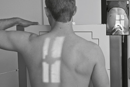
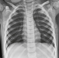
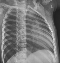
AP or PA (Bilateral) Ribs—Above Diaphragm*

image

Generally taken as AP for posterior ribs and PA for anterior ribs.

• 35 × 43 cm (14 × 17″) C.W. or L.W. (unilateral study or narrow chest dimensions)

• Grid

image

Fig. 7-9 AP bilateral ribs (above diaphragm).

Position

• Erect, or recumbent, midsagittal plane to centerline and CR

• Top of IR ≈1.5″ (4 cm) above shoulders

• Roll shoulders forward, no rotation

• Ensure that thorax is centered to IR (bilateral study).

Central Ray:

CR ⊥, to center of IR and 3 or 4″ (8 to 10 cm) below jugular notch (level of T7)

SID:

72″ (183 cm) erect; 40-48″ (102-123 cm) recumbent

Collimation:

Collimate to region of interest.

Respiration:

Expose on inspiration (diaphragm down).

image

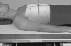
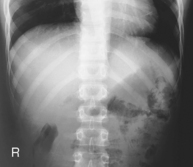
AP Ribs (Bilateral)—Below Diaphragm*

image

• 35 × 43 cm (14 × 17″) C.W or L.W. (unilateral study or narrow chest dimensions)

• Grid

image

Fig. 7-10 AP bilateral ribs (below diaphragm).

Position

• Erect, or recumbent, MSP to centerline of table and IR (and CR)

• Inferior margin of IR at iliac crest

• Ensure that both lateral margins of thorax are included (bilateral study).

• Shield gonads for male and female.

Note:

Some routines include only unilateral ribs of affected side.

Central Ray:

CR ⊥, centered to IR (level of approximately T9-T10, xiphoid process)

SID:

72″ (183 cm) erect; 40-44″ (102-113 cm) recumbent

Collimation:

Collimate to region of interest.

Respiration:

Expose on expiration (diaphragm up).

image

Ribs—AP or PA

(Above and below diaphragm)

Evaluation Criteria

Anatomy Demonstrated:

Above diaphragm:

• Ribs 1-10 visualized

Below diaphragm:

• Ribs 9-12 visualized

Position:

• No rotation, lateral rib margins equal distance from vertebral column

image

Fig. 7-11 AP above diaphragm.
image

Exposure:

• No motion, sharp bony margins

• Contrast and density (brightness) appropriate to visualize ribs 1-10 above diaphragm and 9-12 below diaphragm

image

Fig. 7-12 AP below diaphragm.
image

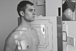
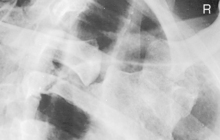
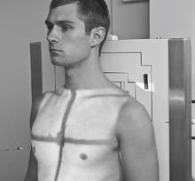
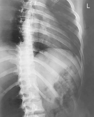
Anterior Oblique Upper Axillary Ribs—RAO*

image

• 35 × 43 cm (14 × 17″) or 30 × 35 cm (11 × 14″) L.W (see Note)

• Grid

image

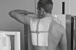
Fig. 7-13 45° RAO above diaphragm—bilateral, right anterior injury (to shift spine away from injury).
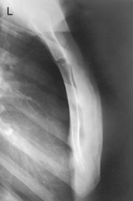
Position

• Erect, or recumbent if needed (erect preferred)

• Oblique 45°, rotate spine away from area of interest

• Involved region of thorax is centered to IR with top of IR ≈4 cm (1.5″) above shoulders

Note:

Some routines indicate unilateral oblique only of affected side with smaller IR placed lengthwise.

Central Ray:

CR ⊥, to center of IR (level of T7)

SID:

72″ (183 cm) erect, 40-44″ (102-113 cm) recumbent

Collimation:

Collimate to region of interest.

Respiration:

Above diaphragm—expose on inspiration.

image

Posterior Oblique Lower Axillary Ribs—LPO*

image

• 35 × 43 cm (14 × 17″) or 30 × 35 cm (11 × 14″) L.W

• Grid

Position

• Erect or recumbent (recumbent preferred)

• Top of IR ≈1.5″ (4 cm) above shoulders

• Rotate 45° from AP, arm closest to IR up, resting on head; opposite hand on waist with arm away from body

image

Fig. 7-14 45° LPO (below diaphragm).

Central Ray:

CR ⊥, centered to IR (level of T7)

SID:

72″ (183 cm) erect, 40-44″ (102-113 cm) recumbent

Collimation:

Collimate to region of interest.

Respiration:

Below diaphragm—expose upon expiration.

image

Anterior or Posterior Oblique Axillary Ribs

(Above and below diaphragm)

Evaluation Criteria

Anatomy Demonstrated:

• LPO/RAO: Visualizes left axillary ribs

• RPO/LAO: Visualizes right axillary ribs

• Ribs 1-10 seen above diaphragm

• Ribs 9-12 seen below diaphragm

• Axillary portion of ribs projected without superimposition

image

Fig. 7-15 LPO above diaphragm.
image

Position:

• 45° oblique should visualize axillary ribs in profile with spine shifted away from area of interest

Exposure:

• No motion, sharp bony margins

• Optimum contrast and density (brightness) visualizes ribs through lungs and heart shadow for above diaphragm, and through dense abdominal organs for below diaphragm

image

Fig. 7-16 LPO below diaphragm.
image


*Bontrager Textbook, 8th ed, p. 362.

*Bontrager Textbook, 8th ed, p. 363.

*Bontrager Textbook, 8th ed, pp. 364 and 365.

*Bontrager Textbook, 8th ed, pp. 366 and 368.

*Bontrager Textbook, 8th ed, pp. 366 and 368.

*Bontrager Textbook, 8th ed, pp. 369 and 370.

*Bontrager Textbook, 8th ed, pp. 369 and 370.