Chapter 8

Skull, Facial Bones, and Paranasal Sinuses

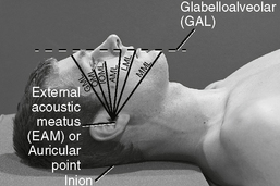
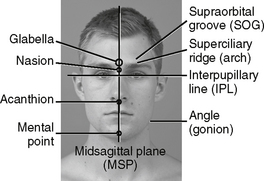
Cranial landmarks and positioning lines used in skull and facial bones positioning.

image

Fig. 8-1 Positioning lines.

Glabellomeatal line (GML)

Orbitomeatal line (OML)

Infraorbitomeatal line (IOML) (Reid’s base line, or “base line,” base of cranium)

Acanthiomeatal line (AML)

Lips-meatal line (LML) (used for modified Waters)

Mentomeatal line (MML) (used for Waters)

image

Fig. 8-2 Cranial landmarks.

AP (PA) Axial Skull*

AP Towne (or PA Haas Method)

image

• 24 × 30 cm L.W. (10 × 12″)

• Grid

Position

image

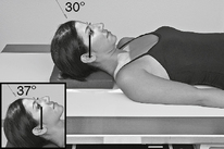
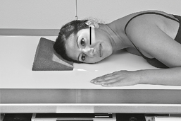
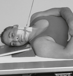
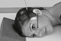
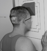
Fig. 8-3 AP axial (Towne)—CR 30° caudad to OML.

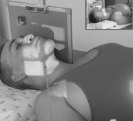
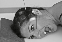
• Seated erect, or supine, midsagittal plane aligned to CR and centerline, perpendicular to IR; no rotation or tilt

• Depress chin to bring OML or IOML perpendicular to IR.

• Center IR to projecting CR.

image

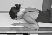
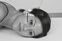
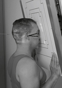
Fig. 8-4 PA axial (Haas method), OML ⊥ CR 25° cephalad, through level of EAMs.

Central Ray:

• CR 30° caudal to OML; or 37° caudal to IOML

• CR to ≈2.5″ or 6 cm above glabella (through 2 cm or 0.75″ superior to level of EAMs)

SID:

40-44″ (102-113 cm)

Collimation:

On four sides to skull margins

Respiration:

Suspend during exposure.

Note:

PA Haas (p. 436 in text) is an alternate to AP Towne. Adjust head to bring OML ⊥ to IR.

image

AP Axial

(Modified Towne Method)

Evaluation Criteria

Anatomy Demonstrated:

• Occipital bone, petrous pyramids, and foramen magnum

Position:

• Dorsum sellae within foramen magnum

• No rotation evident by symmetry of petrous pyramids

Exposure:

• Optimal density (brightness) and contrast to visualize occipital bone

• Sharp bony margins; no motion

image

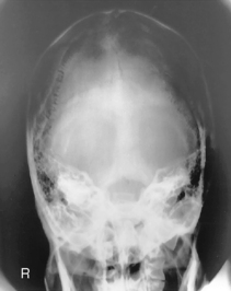
Fig. 8-5 AP axial skull.
image

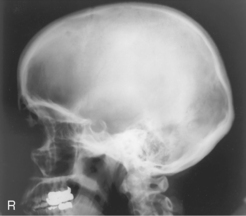
Lateral Skull*

image

• 24 × 30 cm C.W. (10 × 12″)

• Grid

image

Fig. 8-6 Lateral skull.

Position

• Seated erect or semiprone on table

• No rotation or tilt, midsagittal plane parallel to IR, and IPL perpendicular to IR

• Adjust chin to place IOML parallel to upper and lower IR edges

• Center IR to CR.

Central Ray:

CR ⊥ to IR, ≈2″ (5 cm) superior to EAM

SID:

40-44″ (102-113 cm)

Collimation:

On four sides to skull margins

Respiration:

Suspend during exposure.

image

Lateral Skull

Evaluation Criteria

Anatomy Demonstrated:

• Superimposed cranial halves

• Entire sella turcica and dorsum sellae

image

Fig. 8-7 Lateral skull.
image

Position:

• No tilt, evident by superimposition of orbital plates (roofs)

• No rotation, evident by superimposition of greater wings of sphenoid and mandibular rami

Exposure:

• Optimal density (brightness) and contrast to visualize sellar structures

• Sharp bony margins; no motion

PA (0° and 15°) Caldwell Skull*

image

Note: Some departmental routines include a 0° PA to better demonstrate the frontal bone in addition to the 15° PA axial Caldwell.

• 24 × 30 cm L.W. (10 × 12″)

• Grid

Position

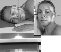
• Seated erect, or prone on table, head aligned to CR and centerline of IR

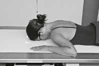
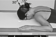
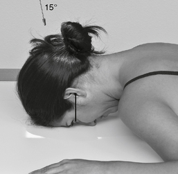
• With forehead and nose resting on tabletop, adjust head to place OML perpendicular to IR.

• No rotation or tilt, midsagittal plane perpendicular to IR

• Center IR to projected CR.

image

Fig. 8-8 PA—0°.

image

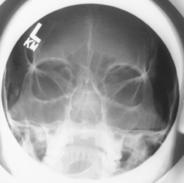
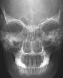
Fig. 8-9 PA axial—15° Caldwell.

Central Ray:

• PA 0°: CR ⊥ to IR, centered to exit at glabella

• PA axial (Caldwell): CR 15° caudad to OML, centered to exit at nasion (25°–30° best demonstrates orbital margins)

SID:

40-44″ (102-113 cm)

Collimation:

On four sides to skull margins

Respiration:

Suspend during exposure.

image

PA (0°) and PA Axial Caldwell (15° Caudad)

Evaluation Criteria

Anatomy Demonstrated:

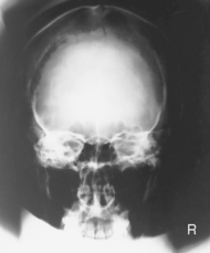
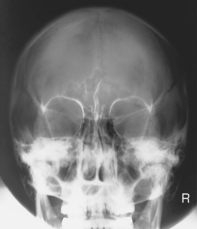
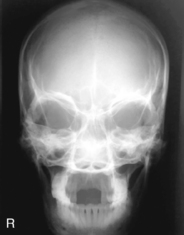
• PA 0°: Frontal bone and crista galli demonstrated without distortion

• PA axial 15°: Greater/lesser wings of sphenoid, frontal bone, and superior orbital fissures

image

Fig. 8-10 PA—0°.
image

Position:

• PA 0°: Petrous ridges at level of superior orbital margin. No rotation; equal distance between orbits and lateral skull

• PA axial 15°: Petrous ridges projected in lower ⅓ of orbits. No rotation; equal distance between orbits and lateral skull

Exposure:

• Optimal density (brightness) and contrast to visualize frontal bone and surrounding structures

• Sharp bony margins; no motion

image

Fig. 8-11 PA axial—15° Caldwell.
image

Submentovertex (SMV) Skull*

image

• 24 × 30 cm L.W. (10 × 12″)

• Grid

• AEC optional

image

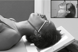
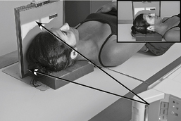
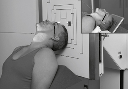
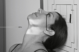
Fig. 8-12 SMV—CR ⊥ to IOML.

Position

• Seated erect or supine with head extended over end of table resting top of head against grid IR (may tilt table up slightly)

• Adjust IR and head to place IOML parallel to IR.

• Ensure no rotation or tilt.

• Center IR to CR.

Central Ray:

CR angled to be ⊥ to IOML, centered to 0.75″ (2 cm) anterior to level of EAMs (midpoint between angles of mandible)

Note:

If patient cannot extend head this far, adjust CR as needed to remain perpendicular to IOML.

SID:

40-44″ (102-113 cm)

Collimation:

On four sides to skull margins

Respiration:

Suspend during exposure.

image

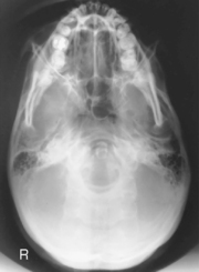
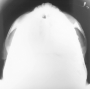
Submentovertex (SMV) Skull

Evaluation Criteria

Anatomy Demonstrated:

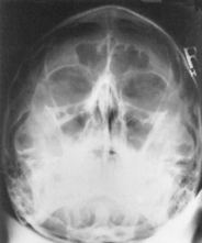
• Base of skull, including mandible and occipital bone

• Foramen ovale and spinosum

Position:

• Mandibular condyles are anterior to the petrous bones

• No tilt; equal distance between mandibular condyles and lateral skull

• No rotation; MSP parallel to edge of radiograph

image

Fig. 8-13 SMV.
image

Exposure:

• Optimal density and contrast (brightness) to visualize outline of foramen magnum

• Sharp bony margins; no motion

Lateral Trauma Skull*

image

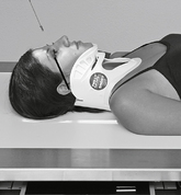
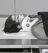
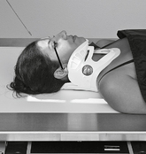
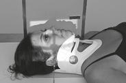
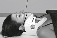
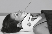
Warning: Do NOT elevate or move patient’s head before cervical spine injuries have been ruled out.

• 24 × 30 cm C.W. (10 × 12″)

• Grid

image

Fig. 8-14 Lateral, with possible spinal injury.

Position

• Supine, without removing cervical collar if present

• With possible spinal injury, move patient to back edge of table and place IR about 1″ (2.5 cm) below tabletop and posterior skull (move floating tabletop forward).

• Center IR to horizontal beam CR (to include entire skull).

• Ensure no rotation or tilt.

Central Ray:

CR horizontal, ⊥ to IR, centered to ≈2″ (5 cm) superior to EAM

SID:

40-44″ (102-113 cm)

Collimation:

On four sides to skull margins

Respiration:

Suspend respiration.

image

AP Trauma Skull Series*

image

Warning: With possible spine or severe head injuries, take all projections AP without moving head or without removing cervical collar if present.

• 24 × 30 cm L.W. (10 × 12″)

• Grid (Bucky)

image

Fig. 8-15 AP—0° to OML.CR—parallel to OML—centered to glabella

Position

• Patient carefully moved onto x-ray table in supine position

• All projections taken as is without moving head

SID:

40-44″ (102-113 cm)

Collimation:

On four sides to skull margins

Respiration:

Suspend during exposure, or take “as is.”

CR Angle and Centering

• As indicated under each photo

• IR centered to projected CR

image

Fig. 8-16 AP reverse Caldwell. CR—15° cephalad to OML—centered to nasion

image

Fig. 8-17 AP axial (Towne). CR—30° caudad to OML—centered to midpoint between EAMs

Lateral Trauma Skull

Evaluation Criteria

Anatomy Demonstrated:

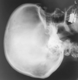
• Superimposed cranial halves

• Entire sella turcica and dorsum sellae

Position:

• No rotation or tilt (see p. 229 for specific criteria)

Exposure:

• Optimal density (brightness) and contrast to visualize sellar structures

• Sharp bony margins; no motion

image

Fig. 8-18 Lateral trauma skull.
image

Trauma AP (0°) and AP Axial (15° Cephalad) Projections

image

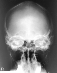
Fig. 8-19 AP—0° to OML.
image

image

Fig. 8-20 AP axial (“reverse” Caldwell) (15° cephalad).
image

Evaluation Criteria

Anatomy Demonstrated:

• AP 0°: Frontal bone and crista galli demonstrated (magnified because of OID)

• AP axial 15°: Greater/lesser wings of sphenoid, frontal bone, and superior orbital fissures (magnified)

Position:

• AP 0°: Petrous ridges at level of superior orbital margin. No rotation; equal distance between orbits and lateral skull

• AP axial 15°: Petrous ridges projected in lower ⅓ of orbits. No rotation; equal distance between orbits and lateral skull

Exposure:

• Optimal density (brightness) and contrast to visualize frontal bone and surrounding structures

• Sharp bony margins; no motion

Facial Bones—Lateral*

image

• 8 × 10″ L.W. (18 × 24 cm)

• Grid

image

Fig. 8-21 Lateral facial bones.

Position

• Seated erect or semiprone on table

• No rotation or tilt, midsagittal plane parallel to IR, IPL perpendicular to IR

• Adjust chin to place IOML parallel to top and bottom edge of IR.

• Center IR to CR.

Central Ray: 

CR ⊥ to IR, centered to midway between EAM and outer canthus

SID:

40-44″ (102-113 cm)

Collimation:

On four sides to area of facial bones

Respiration:

Suspend during exposure.

image

Lateral Facial Bones

Evaluation Criteria

Anatomy Demonstrated:

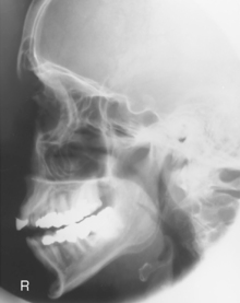
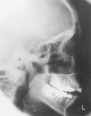
• Superimposed facial bones, greater wings of sphenoid and sella turcica

• Region from orbital roofs to mentum demonstrated

Position:

• No tilt; evident by superimposition of orbital plates (roofs)

• No rotation; evident by superimposition of greater wings of sphenoid and mandibular rami

image

Fig. 8-22 Lateral facial bones.
image

Exposure:

• Optimal density (brightness) and contrast to visualize facial structures

• Sharp bony margins; no motion

Facial Bones—Parietoacanthial*

(Waters and Modified Waters)

image

• 24 × 30 cm L.W. (10 × 12″) or 18 × 24 cm L.W. (8 × 10″)

• Grid

image

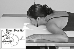
Fig. 8-23 PA Waters, OML 37°—CR and MML ⊥.

image

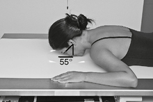
Fig. 8-24 PA modified Waters, OML 55°—CR and LML ⊥.

Position

Waters:

• Seated erect or prone on table

• Extend head resting on chin; place MML ⊥ to IR, which places the OML 37° to IR.

• Center IR to CR.

Modified Waters:

• OML is 55° to the plane of the IR, or line from junction of lips to EAM (LML) is ⊥ to IR.

Central Ray:

CR ⊥ to IR, to exit at acanthion (both projections)

SID:

40-44″ (102-113 cm)

Collimation:

On four sides to area of facial bones

Respiration:

Suspend during exposure.

image

Parietoacanthial and Modified Parietoacanthial

image

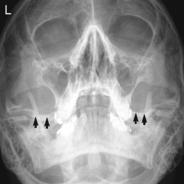
Fig. 8-25 PA Waters.
image

image

Fig. 8-26 PA modified Waters.
image

(Waters and Modified Waters)

Evaluation Criteria

Anatomy Demonstrated:

• Waters: Inferior orbital rims, maxillae, and nasal septum

• Modified Waters: Inferior orbital floors in profile (undistorted)

Position:

• Waters: Petrous ridges just inferior to floor of maxillary sinuses. No rotation; equal distance between orbits and lateral skull

• Modified Waters: Petrous ridges projected in lower ½ of maxillary sinuses. No rotation; equal distance between orbits and lateral skull

Exposure:

• Optimal density (brightness) and contrast to visualize maxillary region and surrounding structures

• Sharp bony margins; no motion

Facial Bones—PA Axial (Caldwell)*

image

• 24 × 30 cm L.W. (10 × 12″) or 18 × 24 cm L.W. (8 × 10″)

• Grid

image

Fig. 8-27 PA axial—15° Caldwell (OML ⊥); CR to exit at nasion.

Position

• Seated erect or prone on table, MSP aligned to CR and to centerline of IR

• With forehead and nose resting on tabletop, adjust head to place OML perpendicular to IR; ensure no rotation or tilt.

• Center IR to projected CR (to nasion).

Central Ray:

CR 15° caudal to OML, centered to exit at nasion

Note:

A 30° CR angle is required to project lower orbits below petrous ridges if this is an area of interest.

SID:

40-44″ (102-113 cm)

Collimation:

On four sides to skull (facial bones) margins

Respiration:

Suspend during exposure.

image

PA Axial (15° Caudad) Caldwell

Evaluation Criteria

Anatomy Demonstrated:

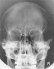
• PA axial 15°: Orbital rims, maxillae, nasal septum, and zygomatic arches

Position:

• PA axial 15°: Petrous ridges projected in lower ⅓ of orbits. No rotation; equal distance between orbits and lateral skull margins

Exposure:

• Optimal density (brightness) and contrast to visualize maxillary region and orbital floor

• Sharp bony margins; no motion

image

Fig. 8-28 PA axial Caldwell—15° caudad.
image

Facial Bones—Trauma Series*

Warning: With possible spine or severe head injuries, take all projections supine without moving head or without removing cervical collar if present.

Lateral (Horizontal Beam)

• 18 × 24 cm L.W. (8 × 10″)

• Grid, placed on edge against lateral cranium

• Ensure no rotation or tilt, MSP parallel to IR

• CR horizontal, to midway between outer canthus and EAM

Reverse Waters

• 18 × 24 cm L.W. (8 × 10″)

• Grid (Bucky), AEC—center field

• MSP aligned to CR and centerline of table or IR

• Ensure no rotation or tilt.

• CR parallel to MML

• CR centered to acanthion (CR angled cephalad as needed unless head can be tilted back if cervical injury has been ruled out).

Reverse Modified Waters

• Same as reverse Waters except:

• CR parallel to junction of lips-meatal line (LML), which is 18°–20° from MML

• CR centered to acanthion

image

Fig. 8-29 Horizontal beam lateral—CR to midway between outer canthus and EAM.

image

Fig. 8-30 Trauma reverse Waters—CR parallel to MML, centered to acanthion.

image

Fig. 8-31 Trauma reverse modified Waters—CR parallel to LML, centered to acanthion.

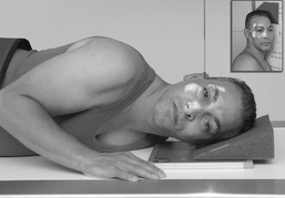
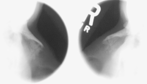
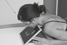
Optic Foramina—Parieto-orbital Oblique*

(Rhese Method)

image

• 18 × 24 cm C.W. (8 × 10″)

• Grid

• R and L sides taken for comparison

• AEC not recommended because of small body part

Position

• Seated erect or prone on table

• As a starting reference, adjust the head so the nose, cheek, and chin are touching the tabletop.

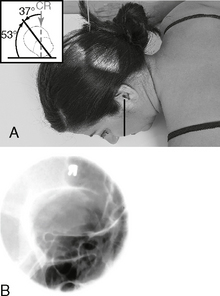
• Adjust the head so the AML is perpendicular to the IR, and the midsagittal plane is 53° to the IR (use angle indicator).

• Center IR to CR (to downside orbit).

image

Fig. 8-32 A, Rhese oblique (right side). B, Rhese oblique. —.AML and CR ⊥ — 53° rotation of head from lateral

Central Ray:

CR ⊥ to IR, to center of downside orbit

SID:

40-44″ (102-113 cm)

Collimation:

Closely collimate to 3-4″ (8-10 cm) square.

Respiration:

Suspend during exposure.

image

Zygomatic Arches—Bilateral*

Submentovertex (SMV) Projection

image

• 18 × 24 cm C.W. (8 × 10″)

• Nongrid or grid

• No AEC

image

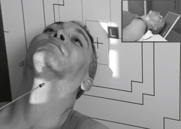
Fig. 8-33 SMV, bilateral zygomatic arches, erect—CR ⊥ to IOML (nongrid may be preferred).

Position

• Seated erect or supine with head extended over end of table resting top of head against grid IR (may tilt table up slightly)

• Adjust IR and head to place IOML parallel to IR.

• Ensure no rotation or tilt.

• Center IR to CR.

Central Ray:

CR angled as needed to be ⊥ to IOML, centered to midway between zygomatic arches (≈1.5″ or 4 cm inferior to mandibular symphysis)

SID:

40-44″ (102-113 cm)

Collimation:

To include area of zygomatic arches

Respiration:

Suspend during exposure.

image

Zygomatic Arches—Tangential*

(Oblique Inferosuperior Projection)

image

Bilateral arches generally taken for comparison.

• 18 × 24 cm C.W. (8 × 10″)

• Nongrid or grid

• AEC not recommended

image

Fig. 8-34 Tangential of left zygomatic arch—CR ⊥ to IOML, head tilted 15°, rotated 15°.

Position

• Position as for an SMV skull with the IOML parallel to the IR.

• Rotate the head ≈15° toward side being examined.

• Tilt the midsagittal plane with the chin toward the side of interest about 15° or as needed to free the zygomatic arch from superimposition by mandible or parietal bone.

• Center IR to CR.

Central Ray:

CR angled if needed to be ⊥ to IOML, centered to mid-zygomatic arch

SID:

40-44″ (102-113 cm)

Collimation:

Collimate closely to area of interest.

Respiration:

Suspend during exposure.

image

Submentovertex (SMV) and Oblique Tangential Zygomatic Arches

image

Fig. 8-35 SMV.
image

image

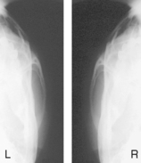
Fig. 8-36 Oblique tangential.
image

Evaluation Criteria

Anatomy Demonstrated:

• SMV: Bilateral zygomatic arches

• Tangential: Unilateral zygomatic arch

Position:

• SMV: Unobstructed view of bilateral arches. No rotation; symmetry of arches.

• Oblique tangential: Unilateral view of unobstructed arch. No superimposition of arch with parietal bone or mandible

Exposure:

• Optimal density (brightness) and contrast to visualize the zygomatic arches

• Sharp bony margins with soft tissue detail; no motion

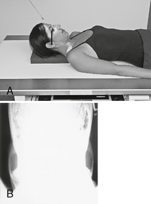
Bilateral Zygomatic Arches—AP Axial*

(Modified Towne)

image

• 18 × 24 cm C.W. (8 × 10″)

• Grid

• AEC not recommended

Position

• Seated erect or supine on table, midsagittal plane aligned to midline of table or IR; ensure no rotation or tilt

• Depress chin to bring either the OML or the IOML perpendicular to IR.

• Center IR to projected CR.

image

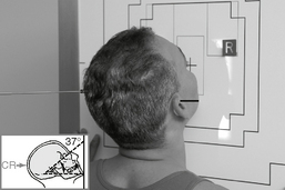
Fig. 8-37 A, AP axial—CR 37° to IOML. B, AP axial.

Central Ray:

• CR 30° caudal to OML; or 37° to IOML

• CR 1″ (2.5 cm) superior to glabella to pass through level of midarches

SID:

40-44″ (102-113 cm)

Collimation:

On four sides to area of bilateral arches

Respiration:

Suspend during exposure.

image

Nasal Bones—Lateral*

image

Bilateral projections generally taken for comparison.

• 18 × 24 cm C.W. (8 × 10″) (bilateral/divided on same IR)

• Nongrid—detail screens

image

Fig. 8-38 Right lateral—nasal bones.

Position

• Seated erect or semiprone on table

• Center nasal bones to half of IR and to CR.

• Adjust head to bring IOML parallel to top and bottom edge of IR.

• Ensure a true lateral, IPL perpendicular to IR, and midsagittal plane parallel to IR.

Central Ray:

CR ⊥ to IR, centered to ≈0.5″(1.25 cm) inferior to nasion

SID:

40-44″ (102-113 cm)

Collimation:

Closely collimate to ≈4″ (10 cm) square.

Respiration:

Suspend during exposure.

image

Lateral Nasal Bones

image

Fig. 8-39 Lateral nasal bones.
image

Evaluation Criteria

Anatomy Demonstrated:

• Nasal bones with soft tissue structures

• Frontonasal suture to anterior nasal spine

Position:

• No rotation; complete profile of nasal bones

• Frontonasal suture to anterior nasal spine within collimation field

Exposure:

• Optimal density (brightness) and contrast to visualize nasal bones and surrounding soft tissue structures

• Sharp bony margins with soft tissue detail; no motion

Nasal Bones*

Superoinferior Axial (Tangential) Projection

image

• 18 × 24 cm C.W. (8 × 10″)

• Nongrid—detail screens

image

Fig. 8-40 Seated.

Position

• Seated erect at end of table or prone on table

• If prone, place supports under chest and under IR.

• Rest extended chin on IR, which should be perpendicular to GAL (glabelloalveolar line) and to CR.

Central Ray:

CR directed parallel to GAL, centered to nasion

SID:

40-44″ (102-113 cm)

Collimation:

Closely collimate to ≈4″ (10 cm) square.

Respiration:

Suspend during exposure.

image

Fig. 8-41 Superoinferior.

image

Mandible—PA and PA Axial*

image

• 18 × 24 cm L.W. (8 × 10″)

• Grid

• AEC not recommended

image

Fig. 8-42 PA mandible—CR and OML ⊥ to IR.)

Position

• Seated erect or prone on table, head aligned to centerline

• With forehead and nose resting on tabletop, adjust head to place OML ⊥ to IR.

• No rotation or tilt, midsagittal plane ⊥ to IR

• Center IR to CR (level of junction of lips).

Central Ray:

CR ⊥ to IR, to exit at level of lips

Note:

A CR angle of 20°–25° cephalad centered to exit at the acanthion best demonstrates proximal rami and condyles.

SID:

40-44″ (102-113 cm)

Collimation:

Collimate to area of mandible (square area).

Respiration:

Suspend during exposure.

image

Mandible—Axiolateral Obliques*

image

R and L sides generally taken for comparison unless contraindicated.
• 18 × 24 cm C.W. (8 × 10″)

• Grid or nongrid

image

Fig. 8-43 Semisupine.

image

Fig. 8-44 Erect.

CR 25° cephalad

10°–15° head rotation for general survey (as shown above)

0° head rotation for ramus

30° head rotation for body

45° head rotation for mentum

Position

• Seated erect, semiprone, or semisupine, with support under shoulder and hip

• Extend chin, with side of interest against IR.

• Adjust head so IPL is perpendicular to IR, no tilt.

• Rotate head toward IR as determined by area of interest.

Central Ray:

CR 25° cephalad to IPL, centered to downside midmandible (≈2″ or 5 cm below upside angle)

SID:

40-44″ (102-113 cm)

Collimation:

To area of mandible (square area)

Respiration:

Suspend during exposure.

image

Mandible—Trauma Axiolateral Oblique*

image

For trauma patients unable to cooperate.

• 18 × 24 cm C.W. (8 × 10″)

• Grid or nongrid

image

Fig. 8-45 Horizontal beam axiolateral—CR 30° cephalad from lateral, 5°–10° down.

Position

• Supine, no rotation of head, MSP ⊥ to TT

• IR on edge next to face, parallel to MSP with lower edge of IR ≈1″ (2.5 cm) below lower border of mandible

• Depress shoulders and elevate or extend chin if possible.

Note:

May rotate head toward IR slightly (10°–15°) to better visualize body or mentum of mandible if this is area of interest.

Central Ray:

• CR horizontal beam, 30° cephalad (from lateral or IPL); angled down (posteriorly) 5°–10° to clear shoulder

• CR centered to ≈2″ (5 cm) distal to angle of mandible on side away from IR

SID:

40-44″ (102-113 cm)

Collimation:

To area of mandible (square area)

Respiration:

Suspend during exposure.

image

PA and Axiolateral Oblique Mandible

image

Fig. 8-46 PA mandible.
image

image

Fig. 8-47 Axiolateral oblique mandible.
image

Evaluation Criteria

Anatomy Demonstrated:

• PA: Mandibular rami and lateral portion of body

• Axiolateral: Mandibular rami, condylar and coronoid processes, and body of near side

Position:

• PA: No rotation evident by symmetry of rami

• Axiolateral: Unobstructed view of mandibular rami, body, and mentum. No foreshortening of area of interest.

Exposure:

• Optimal density (brightness) and contrast to visualize mandibular area of interest

• Sharp bony margins; no motion

AP Axial Mandible*

(Temporomandibular Joints)

image

• 18 × 24 cm L.W. (8 × 10″)

• Grid

image

Fig. 8-48 AP axial, CR 35° to OML (CR centered for mandible).

Position

• Seated erect or supine on table, midsagittal plane centered to midline of table; ensure no rotation or tilt

• Depress chin to bring OML perpendicular to IR if possible (or bring IOML perpendicular and add 7° to CR angle).

• Center IR to projected CR.

Central Ray:

• CR 35° caudad to OML (42° to IOML)

• CR centered to glabella for mandible

Note:

CR centered ≈2″ (5 cm) above glabella to pass through TMJs if TMJs are of primary interest.

SID:

40-44″ (102-113 cm)

Collimation:

To include from TMJs to body of mandible

Respiration:

Suspend during exposure.

image

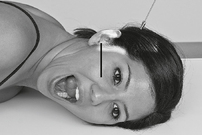
Temporomandibular Joints*

Axiolateral Oblique (Modified Law Method)

image

R and L sides for comparison in both open and closed mouth positions.

• 18 × 24 cm C.W. (8 × 10″)

• Grid

image

Fig. 8-49 Closed mouth.

Position

• Seated erect or semiprone on table, affected side down

• Adjust chin to place IOML parallel to top edge of IR.

• Anterior head (midsagittal plane) rotated 15° toward IR, no tilt, IPL remains perpendicular to IR

• Portion of IR being exposed centered to projected CR

• Second exposure in same position except with mouth fully open

image

Fig. 8-50 Open mouth. —15° oblique (from lateral) and 15° CR (caudad)

Central Ray:

CR 15° caudad, center to exit through downside TMJ (to enter 1.5″ or 4 cm superior to upside EAM)

SID:

40-44″ (102-113 cm)

Collimation:

Collimate to 3-4″ (8-10 cm) square.

Respiration:

Suspend during exposure.

image

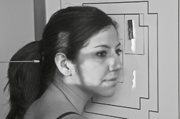
Temporomandibular Joints*

Axiolateral (Schuller Method)

image

R and L sides for comparison in both open and closed mouth positions.

• 18 × 24 cm C.W. (8 × 10″)

• Grid

image

Fig. 8-51 Closed mouth.

Position

• Seated erect or semiprone, affected side down

• Adjust chin to place IOML parallel to top and bottom edges of IR, true lateral, no rotation or tilt of head.

• Portion of IR being exposed centered to projected CR

• Second exposure in same position except with mouth fully open

image

Fig. 8-52 Open mouth. —25° caudad, 0° rotation

Central Ray:

CR 25° caudad, center to exit through downside TMJ (to enter ≈2″ or 5 cm superior and 0.5″ or 1-2 cm anterior to upside EAM)

SID:

40-44″ (102-113 cm)

Collimation:

Collimate to 3-4″ (8-10 cm) square.

Respiration:

Suspend during exposure.

image

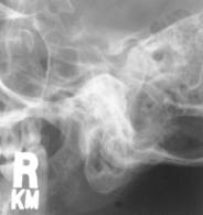
Axiolateral Oblique (Modified Law Method) and Axiolateral (Schuller method) TMJ Projections
image

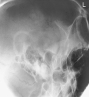
Fig. 8-53 Axiolateral oblique—closed mouth, downside TMJ shown in fossa (modified Law).
image

image

Fig. 8-54 Axiolateral projection—open mouth; TMJ shown with condyle moved to anterior margin of fossa (Schuller).
image

Note:

Positioning routine would require both open and closed mouth of modified Law method, or both open and closed of Schuller method.

Evaluation Criteria

Anatomy Demonstrated:

• Modified Law: Bilateral, functional study of TMJ and fossa

• Modified Schuller: Bilateral, functional study of TMJ and fossa

Position:

• Modified Law: Unobstructed view of TMJ in both open and closed mouth positions (only closed mouth is shown)
• Schuller: Unobstructed view of TMJ in both open and closed mouth positions (only open mouth is shown)

Exposure:

• Optimal density (brightness) and contrast to visualize the TMJ and mandibular fossa

• Sharp bony margins; no motion

Lateral Paranasal Sinuses*

image

Requires an erect position with horizontal CR to demonstrate air-fluid levels.

• 18 × 24 cm L.W. (8 × 10″)

• Grid

• AEC not recommended

image

Fig. 8-55 Erect lateral.

Position

• Erect, seated facing IR, turn head into lateral position

• Adjust height of IR to center IR to level of EAM.

• Raise chin to bring IOML parallel to floor.

• No rotation, midsagittal plane parallel and IPL ⊥ to IR

• Center IR to CR.

Central Ray:

CR horizontal to midpoint between EAM and outer canthus

SID:

40-44″ (102-113 cm)

Collimation:

Collimate on four sides to area of sinuses.

Respiration:

Suspend during exposure.

image

PA Paranasal Sinuses*

(Caldwell Method)

image

Requires an erect position with horizontal CR to demonstrate air-fluid levels.

• 18 × 24 cm L.W. (8 × 10″)

• Grid

• AEC not recommended

image

Fig. 8-56 PA Caldwell (if IR holder can be tilted).

image

Fig. 8-57 Modified PA Caldwell (if IR holder cannot be tilted).

Position

PA Caldwell:

• Seated erect, facing IR, tilt top of IR 15° toward patient

• Adjust head so OML is ⊥ to IR, no rotation.

• IR centered to CR (nasion)

Modified PA Caldwell:

• Tilt head back to bring OML 15° from horizontal.

Central Ray:

CR horizontal, centered to exit at nasion

SID:

40-44″ (102-113 cm)

Collimation:

To area of sinuses

Respiration:

Suspend during exposure.

image

Lateral and PA Caldwell Sinuses

image

Fig. 8-58 Lateral sinuses.
image

image

Fig. 8-59 PA axial (Caldwell) sinuses.
image

Evaluation Criteria

Anatomy Demonstrated:

• Lateral: All paranasal sinuses demonstrated

• PA Caldwell: Frontal and anterior ethmoid sinuses

Position:

• Lateral: No rotation or tilt; superimposition of greater wings/sphenoid, orbital roofs, and sella turcica

• PA Caldwell: Petrous ridges in lower ⅓ of orbits. No rotation; equal distance between orbits and lateral skull

Exposure:

• Optimal density (brightness) and contrast to visualize the paranasal sinuses

• Sharp bony margins with soft tissue detail; no motion

Paranasal Sinuses*

Parietoacanthial (Waters Method)

image

Requires an erect position with horizontal CR to demonstrate air-fluid levels.

• 18 × 24 cm L.W. (8 × 10″)

• Grid

• AEC not recommended

image

Fig. 8-60 PA erect Waters, MML ⊥, and CR horizontal.

Position

• Seated erect, chin extended and touching IR holder

• Adjust height of IR to center IR to acanthion.

• Adjust MML perpendicular to IR (OML is 37° to IR).

• No rotation, midsagittal plane perpendicular to IR holder

• Center IR to CR.

Optional Open-Mouth Position

• Patient opens mouth wide to better visualize sphenoid sinuses through the open mouth

Central Ray:

CR horizontal and ⊥ to IR, to exit at acanthion

SID:

40-44″ (102-113 cm)

Collimation:

Collimate on four sides to area of sinuses.

Respiration:

Suspend during exposure.

image

Paranasal Sinuses*

Submentovertex (SMV)

image

Requires an erect position with horizontal CR to demonstrate air-fluid levels.

• 18 × 24 cm L.W. (8 × 10″)

• Grid

• AEC not recommended

image

Fig. 8-61 SMV sinuses—CR ⊥ to IOML and IR.

Position

• Seated erect, leaning back in chair and extending head to rest top of head against IR holder

• Adjust head to place IOML as near parallel to plane of IR as possible; ensure no rotation or tilt.

• Center IR to CR.

Central Ray:

CR horizontal and ⊥ to IOML, centered to midpoint between angles of mandible

SID:

40-44″ (102-113 cm)

Collimation:

On four sides to area of sinuses

Respiration:

Suspend during exposure.

image

Parietoacanthial (Waters Method) Sinuses and Submentovertex (SMV)

image

Fig. 8-62 PA (Waters) sinuses.
image

image

Fig. 8-63 SMV sinuses.
image

Evaluation Criteria

Anatomy Demonstrated:

• Waters: Unobstructed view of maxillary sinuses

• SMV: Unobstructed view of sphenoid, maxillary, and ethmoid sinuses

Position:

• Waters: Petrous ridges just inferior to floor of maxillary sinuses. No rotation; equal distance between orbits and lateral skull

• SMV: Mandibular condyles projected anterior to petrous bone. No rotation or tilt; symmetry of petrous pyramids and equal distance between mandibular border and lateral skull

Exposure:

• Optimal density (brightness) and contrast to visualize the paranasal sinuses

• Sharp bony margins with soft tissue detail; no motion


*Bontrager Textbook, 8th ed, p. 411.

*Bontrager Textbook, 8th ed, p. 412.

*Bontrager Textbook, 8th ed, pp. 413 and 414.

*Bontrager Textbook, 8th ed, p. 415.

*Bontrager Textbook, 8th ed, p. 594.

*Bontrager Textbook, 8th ed, p. 595.

*Bontrager Textbook, 8th ed, p. 418.

*Bontrager Textbook, 8th ed, pp. 419 and 421.

*Bontrager Textbook, 8th ed, p. 420.

*Bontrager Textbook, 8th ed, p. 597.

*Bontrager Textbook, 8th ed, p. 427.

*Bontrager Textbook, 8th ed, p. 424.

*Bontrager Textbook, 8th ed, p. 425.

*Bontrager Textbook, 8th ed, p. 426.

*Bontrager Textbook, 8th ed, p. 422.

*Bontrager Textbook, 8th ed, p. 423.

*Bontrager Textbook, 8th ed, p. 429.

*Bontrager Textbook, 8th ed, p. 428.

*Bontrager Textbook, 8th ed, pp. 428 and 598.

*Bontrager Textbook, 8th ed, p. 430.

*Bontrager Textbook, 8th ed, p. 434.

*Bontrager Textbook, 8th ed, p. 435.

*Bontrager Textbook, 8th ed, p. 436.

*Bontrager Textbook, 8th ed, p. 437.

*Bontrager Textbook, 8th ed, p. 438.

*Bontrager Textbook, 8th ed, p. 439.