Chapter 10

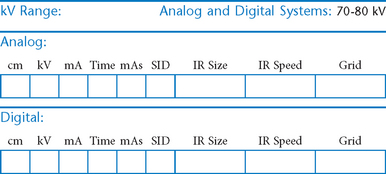
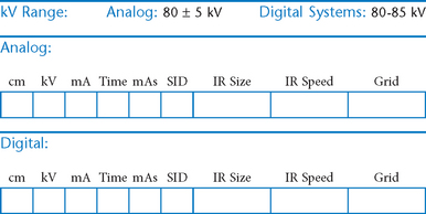
Mobile (Portables) and Surgical Procedures
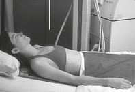
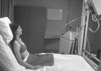
Essential Principles for Trauma and Mobile Radiography

The following three principles must be observed for trauma and mobile procedures:

• Two projections 90° to each other (minimum): Trauma radiography generally requires two projections taken at 90° (or right angles to each other) while true CR-part-IR alignment is maintained.

• Entire anatomic structure or trauma area on image receptor: Trauma radiography mandates that the entire structure being examined should be included on the radiographic image to ensure that no pathologic condition is missed. Additional projections must be taken if the entire structure is not seen on the initial image.

• Maintain the safety of the patient, health care workers, and the public: Technologist must maintain the safety and well-being of patients, family/friends, and other health workers during a trauma or mobile radiographic procedure. Safe handling of patients and radiation protection of the patient and others in the immediate vicinity of the exposure is the responsibility of the technologist.
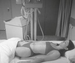
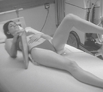
Mobile—AP Chest*

image

• 35 × 43 cm C.W. or L.W. (14 × 17″)

• Nongrid or grid

image

Fig. 10-1 Supine AP chest.

Position

• Cover IR with pillowcase or other cover, center to patient with top of IR approximately 2″ (5 cm) above shoulders.

• Elevate head end of bed if possible into seated or semierect position.

• Ensure no rotation of patient.

• If patient is able, rotate shoulders forward.

image

Fig. 10-2 Semierect AP chest.

Central Ray:

• CR 3°–5° caudal from perpendicular to IR so as to be perpendicular to sternum (prevents clavicles from obscuring apices of lungs)

• Center CR to 3-4″ (8-10 cm) below jugular notch.

SID:

48-72″ (123-183 cm). Use greater SID if possible.

Respiration:

Expose after second full inspiration.

image

Mobile—AP Abdomen (KUB)*

image

• 35 × 43 cm (14 × 17″) L.W.

• Grid

image

Fig. 10-3 AP supine abdomen.

Position

• Cover IR with pillowcase or cover.

• Center IR to patient at level of iliac crest.

• Place pads under IR if needed to keep IR level in the soft bed or surface so as to be perpendicular to CR.

Central Ray:

CR perpendicular to IR, centered to IR at level of iliac crest

SID:

40-44″ (102-113 cm)

Respiration:

Expose on expiration

image

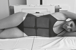
Mobile—Lateral Decubitus*

Abdomen

image

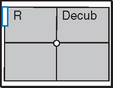
Left lateral best demonstrates free air in right upper abdomen. Must include diaphragm.

• 35 × 43 cm (14 × 17″) L.W. (to anatomy)

• Grid

• Decubitus marker

image

Fig. 10-4 AP left lateral decubitus abdomen.

Position

• Patient turned on left (or right if indicated) side with pads or positioning board under hip and thorax as shown to prevent sinking into soft bed

• Center of IR 2″ (5 cm) above level of iliac crest to include diaphragm

• Ensure no rotation, and that IR is not tilted but is perpendicular to CR.

Central Ray:

Horizontal CR to center of IR 1-2″ (3-5 cm) above iliac crest

SID:

40-44″ (102-113 cm)

Respiration:

Expose on expiration.

Note:

Have patient on side 5 minutes (minimum) before making exposure; 10 to 20 minutes is preferred. Ensure that diaphragm and upside of abdomen are included.

image

Mobile—AP Pelvis or Hip*

Pelvis

image

• 35 × 43 cm (14 × 17″) C.W.

• Grid

image

Fig. 10-5 AP pelvis (trauma hip without leg rotation).

image

Fig. 10-6 AP hip (with leg rotation).

Hip Only

• 24 × 30 cm (10 × 12″) L.W.

• Grid

Position—Pelvis

• Cover IR with pillowcase or cover, slide IR under patient centered crosswise to patient.

• Top of IR about 1″ (2.5 cm) above iliac crest

• Ensure no rotation of patient (equal ASIS distances to IR).

• Internally rotate both legs 15° only if hip fracture is not suspected

Central Ray:

CR perpendicular to IR centered to IR and to pelvis or hip

AP Hip:

Center CR and IR to hip region (2″ or 5 cm medial to ASIS at level of greater trochanter)

SID:

40-44″ (102-113 cm)

Respiration:

Suspend during exposure.

image

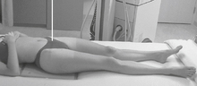
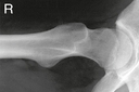
Mobile—Axiolateral Hip*

(Danelius-Miller Method)

image

• 24 × 30 cm (10 × 12″) C.W.

• Grid

image

Fig. 10-7 Axiolateral hip.

Position

• Place folded towels or support under affected hip.

• Place vertical grid against patient’s side with top of IR just above iliac crest with face of grid parallel to femoral neck and perpendicular to CR.

• Elevate opposite leg (Do NOT support leg/foot on collimator or tube because of risk for burns or electrical shock.)

• Internally rotate affected leg only if unsecured hip fracture is not suspected.

Central Ray:

Horizontal CR angled to be perpendicular to IR and femoral neck

SID:

40-44″ (102-113 cm)

Respiration:

Suspend during exposure.

image

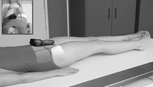
Mobile—Modified Axiolateral Hip and Proximal Femur*

(Clements-Nakayama Method)

image

Alternative projection if both limbs have limited movement and the inferosuperior projection cannot be obtained
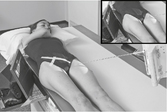
• 24 × 30 cm (10 × 12″) C.W.

• Grid (aligned to CR angle to prevent grid cutoff)

image

Fig. 10-8 Modified axiolateral projection.

image

Fig. 10-9 Lateral proximal femur (modified axiolateral projection).

Position

• Patient supine, affected side near edge of table with both legs fully extended

• Provide pillow for head, and place arms across superior chest.

• Maintain leg in neutral (anatomic) position.

• Rest IR on extended Bucky tray, which places the bottom edge of the IR about 2″ (5 cm) below the level of the tabletop.

• Tilt IR approximately 15° from vertical and adjust alignment of IR to ensure that face of IR is perpendicular to CR to prevent grid cutoff.

• Center centerline of IR to projected CR.

Central Ray:

• Angle CR mediolaterally as needed so that it is perpendicular to and centered to femoral neck (approximately 15° to 20° posteriorly from horizontal).

SID:

40-44″ (102-113 cm)

image

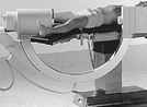
Surgical (Mobile) C-Arm
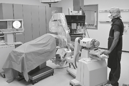
PA Abdomen (Cholangiogram)

Position and CR

• PA projection (patient supine): Image intensifier on top, tube below

• Keep intensifier as close to patient as possible to reduce scatter.

• Provide lead aprons or portable shields for all personnel in room.

• Maintain sterile field.

• Auto or manual exposure control

• Foot pedal allows hands-free operation by physician of fluoro image as displayed on monitor

image

Fig. 10-10 C-arm being positioned for PA hip or abdomen.

Notes:


C-Arm Lateral Hip

Position and CR

• Superoinferior projection

• Horizontal CR, x-ray tube superior, intensifier inferior

• Ensure sterile field

• Provide lead aprons or shields

• Background exposure field greatest at tube end; operator should stand back away from tube region

image

Fig. 10-11 C-arm for lateral hip. Courtesy Philips Medical System.

Note:

Recommended setup is a reversal of this as an inferosuperior projection because of increased radiation at tube end.

Notes:


Surgical or Mobile Procedures

Procedure Notes:

______________________________________________________________

______________________________________________________________

______________________________________________________________

______________________________________________________________

______________________________________________________________

______________________________________________________________

______________________________________________________________

______________________________________________________________

______________________________________________________________

______________________________________________________________

______________________________________________________________

______________________________________________________________

______________________________________________________________

______________________________________________________________

______________________________________________________________

______________________________________________________________

______________________________________________________________

______________________________________________________________

______________________________________________________________

______________________________________________________________

______________________________________________________________

______________________________________________________________

______________________________________________________________

______________________________________________________________

______________________________________________________________

______________________________________________________________

______________________________________________________________

______________________________________________________________


*Bontrager Textbook, 8th edition, p. 577.

*Bontrager Textbook, 8th edition, p. 580.

*Bontrager Textbook, 8th edition, p. 580.

*Bontrager Textbook, 8th edition, p. 589.

*Bontrager Textbook, 8th edition, p. 590.

*Bontrager Textbook, 8th edition, p. 286.