Chapter 12 Equipment
Anaesthetic Equipment
Gases
Cylinders
Gas cylinders are manufactured from chromium molybdenum steel as a seamless tube.
Colours. Conform to International Standards Organization (Table 12.1).
Table 12.1 Gas cylinder colours
| Body | Shoulder | |
|---|---|---|
| Oxygen | Black | White |
| Nitrous oxide | French blue | French blue |
| Air | Grey | Black/white |
| Carbon dioxide | Grey | Grey |
| Helium | Brown | Brown |
| Cyclopropane | Orange | Orange |
| Entonox | French blue | French blue/white |
| Nitric oxide | Pink | Pink |
Marks on cylinders. Test pressure, dates of test, chemical formula of gas and tare weight (i.e. weight when empty).
Vacuum
Vacuum required to give 0.53 kPa pressure below atmospheric pressure, producing 40 L/min suction of air.
Anaesthetic machine safety features
Checking Anaesthetic Equipment 3
Association of Anaesthetists of Great Britain and Ireland 2004
Full checklist is the responsibility of the anaesthetist and should be performed prior to each operating session.
Note: Some anaesthetic workstations may enter an integral self-test programme when switched on; those functions tested by such a programme need not be retested.
Note: Carbon dioxide cylinders should not be present on the anaesthetic machine unless requested by the anaesthetist. A blanking plug should be fitted to any empty cylinder yoke.
Vaporizers
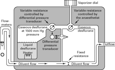
Because desflurane has such a high saturated vapour pressure (88 kPa), standard vaporizers are unsuitable for its storage and delivery. Use of a conventional vaporizer would require very high fresh gas flows to achieve 1 MAC equivalent of desflurane. The low boiling point of desflurane (24°C) also makes a conventional vaporizer unsuitable. The Tech 6 desflurane vaporizer (Fig. 12.1) uses a servo-controlled electronic system which heats the vaporizer chamber to a constant 39°C (higher than the boiling point) at a pressure of 1500 mmHg. The desflurane is delivered into the fresh gas flow (FGF) at equal pressures through a pressure-regulating valve which increases desflurane delivery as the FGF increases. Unlike conventional ventilators, use of the Tech 6 vaporizer at high altitude requires manual adjustment to increase desflurane concentrations.
Ventilators
Nuffield 200 series ventilator
This is a time-cycled pressure generator. It has variable expiratory and inspiratory timers and a variable inspiratory flow rate control (Fig. 12.2).
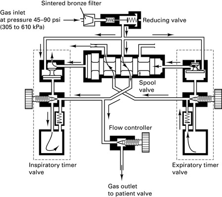
Figure 12.2 Nuffield Penlon 200 ventilator – inspiratory mode.
(Reproduced with permission from Davey et al 1992.)
Paediatric Newton valve. Capable of delivering tidal volume between 10 and 300 mL at flow rates of 0.5–18 L/min. At small tidal volumes, pressure-controlled ventilation is preferable to volume-controlled ventilation because the final volume delivered is dependent upon circuit leaks, circuit compliance and fresh gas flow rates.
Andrews J.J., Johnston R.V. The new Tech 6 desflurane vaporizer. Anesth Analg. 1993;76:1338-1341.
Association of Anaesthetists of Great Britain and Ireland. Checking anaesthetic equipment, vol 3. AAGBI, London, 2004.
Cartwright D.P., Freeman M.F. Vaporisers. Anaesthesia. 1999;54:519-520.
Davey A., Moyle J.T., Ward C.S., editors. Ward’s anaesthetic equipment, ed 3, London: WB Saunders, 1992.
Gardner M.C., Adams A.P. Anaesthetic vaporizers: design and function. Curr Anaesth Crit Care. 1996;7:315-321.
Howell R.S.C. Medical gases (1) Manufacture and uses. Kaufman L., editor. Anaesthesia review, vol 7. Churchill Livingstone, Edinburgh, 1989;87-104.
Howell R.S.C. Medical gases (2) Distribution. Kaufman L., editor. Anaesthesia review, vol 8. Churchill Livingstone, Edinburgh, 1990;195-210.
Breathing Circuits
Mapleson’s classification of breathing systems
For all adult circuits, a 110 cm hose holds a volume of 550 mL. T-piece reservoir should equal the tidal volume (more reservoir volume causes increased resistance and re-breathing).
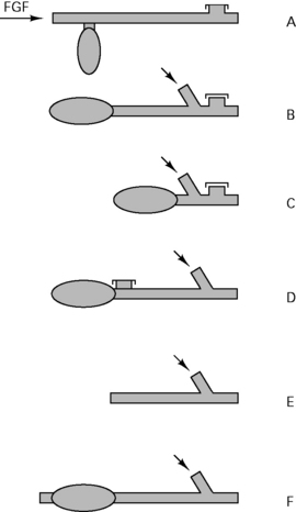
Table 12.2 Breathing circuit flow rates
| Mapleson classification | Spontaneous ventilation | IPPV |
|---|---|---|
| A | 70 mL/kg per min | 2.5 × MV |
| B | 2.5 × MV | 2.5 × MV |
| C | 2.5 × MV | 2.5 × MV |
| D | 2.5 × MV | 70 mL/kg per min |
| E - Adult | 2.5 × MV | 2.5 × MV |
| E < 20 kg | 3 (1000 + 100 mL/kg) | 1000 + 100 mL/kg (minimum flow = 3 L) |
| or | 3 (5 × frequency × kg) | 5 × frequency × kg |
| Lack (coaxial A) | 50 mL/kg per min | |
| Bain (coaxial D) | 70 mL/kg per min |
Paediatric circuits
Deadspace and resistance are most important during spontaneous respiration. Circuit resistance is higher with smaller circuits (∝ 1/r4). Use of low flows with T-piece or Bain circuit results in carbon dioxide being re-breathed only at the latter part of inspiration, which may not affect alveolar ventilation. Re-breathed gas has the advantage of being warm and humidified.
Circle systems
Re-breathing was introduced by Snow in 1850. Circle systems were pioneered by Sword in 1926.
Anaesthetic circuits
Carbon dioxide absorber
Size 4–8 mesh (i.e. granules ¼ – ⅛ inch in diameter); 50% volume of canister is granules, 50% is air. Pack tightly to avoid channelling.
Reaction of soda lime
Temperature within canister may exceed 60°C. Canister should at least equal tidal volume. Therefore, minimum 500 g soda lime becomes exhausted after about 2 h; 100 g soda lime can theoretically absorb 25 L of CO2, but this figure is reduced by channelling and uneven absorption. Large cylinders contain 2 kg soda lime which can be inverted once the upper chamber becomes exhausted. ‘Regeneration’ of soda lime on standing occurs due to migration of hydroxyl ions to the surface of granules.
Circle layout
There are 64 different possible combinations of layout. The most efficient has been found to be that shown in Figure 12.4.
Equilibration of circle gases
The wash-in and wash-out curves for changes in vapour concentration within a closed circuit are exponential. Assuming net gas uptake is minimal:
For example, in a circuit of volume 4 L with FGF = 8 L/min, Tc = 0.5 min. Therefore, 95% of any change in the percentage of volatile selected will be reflected in the circuit within 1.5 min (Tc × 3). However, at low FGF, e.g. 1 L/min, Tc = 2 min and therefore 95% equilibration will not be achieved until 12 min. Hence, increase flow rather than volatile to deepen anaesthesia.
At low flow rates of O2 and N2O into a circle system, the uptake of N2O exceeds that of O2, and the [O2] in the circle exceeds that set by the rotameters. After 30 min equilibration, uptake of N2O is less than that of O2, and the [N2O] in the circle exceeds that set by the rotameters. After the start of an anaesthetic, 15 mL/kg N2 will be released from tissues, lowering [N2O]. This effect is lessened with denitrogenation prior to closing the circuit.
Thus it is difficult to predict exact concentrations of gases, so use of anaesthetic gas monitoring is mandatory to prevent hypoxic mixtures or mixtures that are deficient in volatile, resulting in awareness. Monitor expired gases, which are a better reflection of alveolar gas concentrations than inspired gases.
Principles of closed circuit volatile administration
Direct administration of volatiles into the circuit was pioneered by Lowe.
Uptake of volatile ∝ 1/√time, so the same dose of volatile is taken up between each square of time after induction, i.e. 1, 4, 9, 16, etc. min. Thus one dose is taken up by 1 min after induction, two doses by 4 min after induction, three doses by 9 min after induction, etc. This does not take into account the amount of volatile needed to prime the circuit or any uptake by soda lime or rubber in the circuit. Therefore, extra priming dose needs to be given within the first 9 min.
Aim for ED95 of volatile within circuit, i.e. ≈︀1.3 MAC. Thus, at any time after induction, volatile anaesthetic uptake is as follows:

Vaporizer outside circle (VOC)
At high FGFs, the volatile concentration inspired by the patient will approach that leaving the vaporizer (Fig. 12.5).
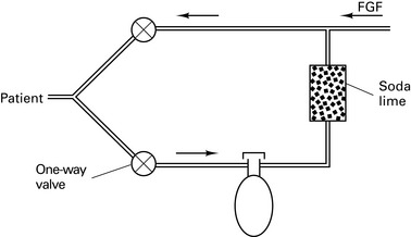
Vaporizer inside circle (VIC)
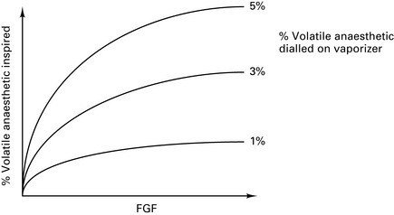
At low FGFs, the volatile concentration inspired by the patient will be much higher than that leaving the vaporizer (Fig. 12.6).
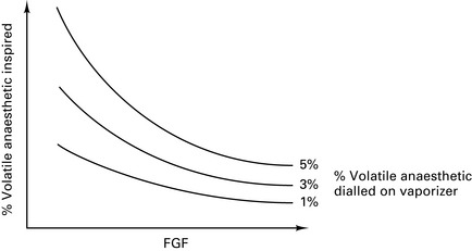
Figure 12.6 Effect of fresh gas flow (FGF) on the percentage of volatile inspired for vaporizers inside the circle.
Draw-over vaporizers for VIC must not have wicks, because water vapour from saturated gases condenses on them to cause inaccurate volatile delivery. Need draw-over vaporizer with low internal resistance if using spontaneous respiration, e.g. Goldman vaporizer. Plenum vaporizers have too high an internal resistance.
Products of reactions with absorbents
Carboxyhaemoglobinaemia
In 1995, reports were received from the USA of patients developing significant carboxyhaemoglobinaemia during anaesthesia. This phenomenon was only observed while using halogenated volatile agents (enflurane, isoflurane, desflurane) in association with circle systems. Cases usually occurred on Monday mornings when oxygen had been left flowing through the circuit over the weekend.
Further investigation found that barium hydroxide (baralyme) in the canister was generating significant amounts of carbon monoxide, particularly at low water content as it dried out. Dry baralyme or soda lime (e.g. gas flowing through an anaesthesia circuit over a weekend period) results in excessive carbon monoxide formation due to reaction with KOH, which may reach fatal levels (35 000 ppm CO documented with desflurane; safe limit is 35 ppm for 1 h). In the UK, barium hydroxide is not available and soda lime (⅓ the amount of KOH compared with baralyme) only dries significantly (<2% water) in circuits where the FGF is placed upstream from the absorbent canister – an arrangement not found in circle systems in the UK. No cases of carboxyhaemoglobinaemia have been reported in the UK and it is thought unlikely that the problems seen in the USA will occur in the UK.
Compound A
Trichloroethylene is decomposed by soda lime to phosgene (toxic). Sevoflurane is decomposed by soda lime and baralyme to compounds A, B, C, D and methanol. Concentrations of compound A in circle systems produce renal injury in rats, but humans are less sensitive. Now believed that compound A has a considerable margin of safety in humans at the concentrations typically found during low-flow sevoflurane anaesthesia (around 15 ppm). Nevertheless, the Food and Drugs Administration (regulatory body for the USA) has set a 1 L.min−1 lower limit for gas flow during sevoflurane anaesthesia. No limit exists in the UK.
In 1999, a novel absorbent was introduced (Amsorb) which contains no strong alkali. Amsorb utilizes hygroscopic agents to ensure that the CaOH does not dry. Amsorb therefore produces no carbon monoxide or compound A.
Excessive heat
In November 2003, the Food and Drugs Administration issued a warning relating to 16 cases of overheating in breathing systems when sevoflurane was being used. The cause was a reaction between the volatile agent and dry KOH. The cases reported from the USA included melting of absorber canisters, smoke, and two explosions. No such incidents have ever been reported in the UK.
Baxter P.J., Garton K., Kharasch E.D. Mechanistic aspects of carbon monoxide formation from volatile anesthetics. Anesthesiology. 1998;89:929-941.
Committee on Safety of Medicines. Circle systems and volatile agents. Curr Prob. 1997;23:7.
Jones M.J. Breathing systems and vaporizers. In: Nimmo W.S., Rowbotham D.J., Smith G., editors. Anaesthesia. ed 2. Oxford: Blackwell Scientific; 1994:486-505.
Nunn G. Low-flow anaesthesia. Contin Educ Anaesth, Crit Care Pain. 2008;8:1-4.
Schober P., Loer S.A. Closed system anaesthesia – historical aspects and recent developments. Eur J Anaesthesiol. 2006;23:914-920.
Monitoring
Inadequate monitoring or observation causes 8.2% of all anaesthetic fatalities; 90% of ‘monitor-detectable’ incidents would be picked up with the correct use of pulse oximetry or capnography.
Recommendations for Standards of Monitoring During Anaesthesia and Recovery
Association of Anaesthetists of Great Britain and Ireland 2007 (4E)
The Association of Anaesthetists of Great Britain and Ireland regards it as essential that certain core standards of monitoring must be used whenever a patient is anaesthetized. These minimum standards should be uniform irrespective of duration, location or mode of anaesthesia.
Inspired oxygen concentration
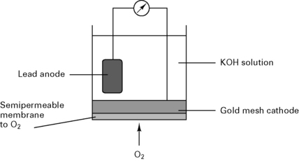
Fuel cell
In a fuel cell (Fig. 12.7), the current is proportional to the partial pressure of oxygen:
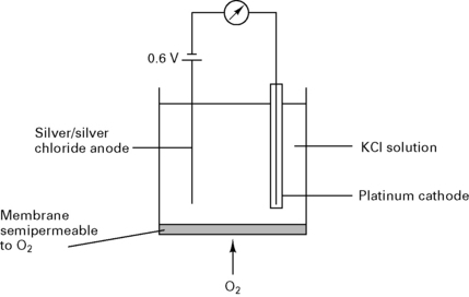
Clarke electrode
In a Clarke electrode (Fig. 12.8) the current is proportional to the partial pressure of oxygen. This type of electrode is usually used in blood gas machines.
Paramagnetic analysis
Based on the fact that oxygen is paramagnetic and attracted towards magnetic fields. Most other gases are diamagnetic and repelled from magnetic fields.
Dumb-bells analyser. Consists of nitrogen-filled dumb-bells with each ball resting within a magnetic field. Any oxygen in the sample gas is attracted into the magnetic field and displaces the nitrogen dumb-bells out of the magnetic field. As the dumb-bells swing, a mirror attached to them displaces a light beam onto photocells.
Datex analyser. The sample gas is separated from the reference gas by a thin diaphragm attached to a pressure transducer. An alternating current applied to the gases causes pressure oscillations across the diaphragm, which is displaced in proportion to the oxygen concentration in the sample gas.
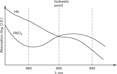
Pulse oximeter
Mechanism
Light is transmitted through tissue at two alternating wavelengths:
Beer’s law, used to calculate the absorption (Fig. 12.9), states:

It = intensity of reflected light
Io= intensity of incident light
d = distance light is transmitted through liquid
e = extinction coefficient of solute.
The pulse oximeter measures the variation in absorption caused by the arterial pulse, cancelling out the effects of other tissues, venous blood and background light (Fig. 12.10). It is accurate to within 2%, but falls to ± 5% with saturations below 80%.
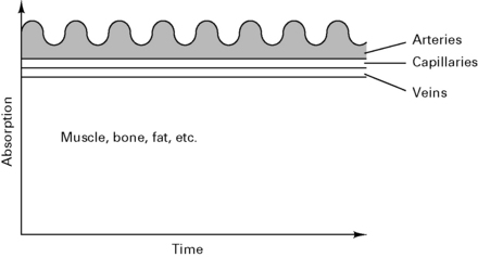
Figure 12.10 Composition of the absorption spectra.
(Reproduced with permission from Davey et al 1992.)
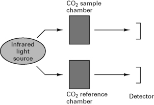
Capnography
Uses spectrophotometry to measure absorption of CO2 in sample chamber (Beer’s law) and compares results with known CO2 concentration in a reference chamber (Fig. 12.11).
Arrangement of sampling chamber
Patterns of capnography displays
IPPV. During ventilation with a Bain circuit, PETCO2 does not return to zero during inspiration because FGF is less than the minute volume. During inspiration, the trace is distorted by the mixing of expired and fresh gas.
Severe COAD causes a prolonged sloping expiratory phase because of the wide spread in V/ values. Alveoli emptying last have the least ventilation, the lowest V/
 and thus the highest PETCO2.
Pulmonary embolus causes a flat expiratory plateau that is lower than the true PETCO2 because of dilution of expiratory gases with air from non-perfused alveoli.
Shunting, e.g. secretions blocking alveoli, causes a rise in PETCO2, but the difference is only small since the AV difference is only ≈︀0.6 kPa.
Clinical uses
Volatile agent monitoring
Drager Narcotest halothane indicator
Uses a rubber band under tension attached to a pointer. Halothane is absorbed by rubber, causing change in elasticity and thus length of the rubber band. Only measures to 3%.
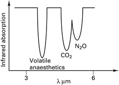
Infrared absorption spectroscopy
Asymmetric, polyatomic molecules absorb infrared radiation, e.g. CO2, N2O. H2 and O2 do not. Similar arrangement as the capnograph CO2 detector. Volatile agents have overlapping absorption spectra (Fig. 12.12) and therefore the gas being measured must be specified.
Non-invasive blood pressure
Finapres
Utilizes the technique of Penaz. Digital cuff is servo-controlled so that its pressure is equal to the blood pressure in that digit. The pressure waveform of the cuff is calibrated with the systolic, diastolic and mean blood pressures from a conventional cuff and displayed continuously on an oscilloscope. Less accurate with peripheral vasoconstriction and susceptible to movement artefact.
Arterial tonometry
Microtransducers compress a large artery, e.g. brachial, and continuously monitor the arterial blood pressure. Calibrated by standard BP cuff. Not yet available commercially.
Pulse wave detection velocity
Two photometric sensors at different sites, e.g. forehead and finger, compare rate of propagation of the arterial pulse, which is related to blood pressure. Viscoelasticity decreases with age and may affect accuracy in the elderly. Calibrated by standard BP cuff. Not yet available commercially.
Central venous pressure
IPPV increases intrathoracic pressure and overestimates mean CVP. Spontaneous respiration decreases intrathoracic pressure and underestimates mean CVP. Measure the peak pressure of the ‘a’ wave during the end-expiratory pause.
Right atrial pressure is a reasonable indicator of left atrial pressure with normal myocardial and pulmonary function.
Association of Anaesthetists of Great Britain and Ireland. Recommendations for standards of monitoring during anaesthesia and recovery: report of a Working Party, ed 4. London: AAGBI; 2007.
Lennmarken C., Vegfors M. Advances in pulse oximetry. Curr Opin Anaesth. 1998;11:639-644.
Moyle J.T.B. Pulse oximetry. Principles and practice series. London: BMJ Publishing; 1994.
O’Flaherty D. Capnography. Principles and practice series. London: BMJ Publishing; 1994.
Runciman W.B., Ludbrook G.L. Monitoring. In: Nimmo W.S., Rowbotham D.J., Smith G., editors. Anaesthesia. ed 2. Oxford: Blackwell Scientific; 1994:704-739.
Physics
Gas laws
Henry’s law. Amount of gas dissolved ∝ partial pressure of the gas.
Fick’s law. Rate of diffusion across a membrane ∝ concentration gradient.
Graham’s law. Rate of diffusion ∝ 1/molecular weight.
Charles’ law. The volume of a gas changes in proportion to the change in temperature.
Boyle’s law. The volume of a gas is inversely proportional to pressure.
Gay-Lussac’s law. At constant volume, the absolute pressure of a given mass of gas varies directly with the absolute temperature.
Adiabatic change. A change in pressure, volume or temperature without changes in energy of gas (i.e. heat is lost or added).
Avogadro’s hypothesis
Equal volumes of ‘ideal’ gases at the same temperature and pressure contain the same number of molecules. (Avogadro’s number = 6.022 × 10²³ molecules occupying 22.4 L at STP.)
Pressure
Dalton’s law of partial pressures. The pressure exerted by a mixture of gases is equal to the sum of the pressures which each gas would exert on its own.
Vapour pressure. A vapour is saturated when it is in equilibrium with its own liquid, i.e. as many molecules leave the surface as rejoin it. When vapour pressure equals atmospheric pressure, the liquid boils.
Solubility
Ostwald solubility coefficient. The amount of gas that dissolves in unit volume of liquid under the stated temperature and pressure.
Bunsen solubility coefficient. The amount of gas that dissolves in unit volume of liquid at standard temperature (273 K) and pressure (101.3 kPa).
Temperature
Critical temperature. Temperature above which a gas cannot be liquefied.
Critical pressure. Pressure above which a gas at its critical temperature cannot be liquefied.
Pseudocritical temperature. Temperature at which a mixture of gases separate out into their separate components, e.g. N2O and O2 in Entonox at −5.5°C.
Specific heat capacity. Amount of heat required to increase the temperature of a substance by 1°C/kg.
Gas flow
Hagen–Poiseuille equation. For laminar flow:

where P = pressure, r = tube radius, L = tube length, η = viscosity.
Liquid tends to flow smoothly in straight and uniform tubes. Abrupt changes in diameter or direction of flow cause turbulent flow, which is dependent upon density (ρ) rather than viscosity.

When Reynold’s number (R) exceeds 2000, flow becomes turbulent:

Bernoulli effect. Fall of pressure at a constriction in a tube. Increased gas/fluid velocity results in increased kinetic energy with a reduction in potential energy and thus a decrease in pressure.
Venturi devices use the Bernoulli effect for suction, e.g. Venturi oxygen mask.
Coanda effect. Streaming of gas at a division in tubing along only one of the divisions. Used as logic valve in some ventilators.
Poynting effect. A mixture of gases (e.g. Entonox) remains in a gaseous state, even though one component (N2O) would normally be liquid at high storage pressures.
Humidification
Absolute humidity is the mass of water vapour present in a given volume of air.
Relative humidity is the ratio of the mass of water vapour to the mass of water vapour when fully saturated, expressed as a percentage.
Methods of humidification
Electricity
Macroshock. Skin-to-skin contact:
Microshock. Direct myocardial contact. Current ≥100 µA. Less effect at higher frequency, e.g. diathermy at 20 kHz.