Diagnostic imaging
Procedure: Rostro-caudal view – open mouth
Procedure: Rostro-caudal view – closed mouth
Procedure: Lateral view of the skull
Procedure: Lateral oblique view
Procedure: Dorso-ventral intra-oral view
Procedure: Ventro-dorsal intra-oral view
Procedure: Ventro-dorsal open mouth oblique rostro-caudal view
Procedure: Intravenous urography for examination of the kidneys and ureters
Procedure: Cystography – examination of the bladder using contrast material
Procedure: Retrograde urethrography for examination of the urethra using positive contrast in the male
Procedure: Retrograde vaginourethrography for examination of the vagina and urethra using positive contrast in the female
There is no doubt that the use of ‘pictures’ makes it much easier to confirm a diagnosis and nowadays there are several methods of taking this ‘picture’. The majority of practices have facilities for radiography and most have ultrasound. This chapter will describe the basic use of both techniques, but it is not the brief of the book to describe the more complicated ways of creating an image such as magnetic resonance imaging (MRI), computed tomography (CT) or nuclear scintigraphy. These three imaging techniques are advanced and require expensive, and in some cases cumbersome, equipment making them currently unavailable to all but the most sophisticated referral practices.
Radiography
Radiography may be defined as all the procedures involved in the production of a radiograph of diagnostic quality and is very often carried out by a veterinary nurse. It involves cleaning and maintenance of the equipment, whatever its type, and the vital correct positioning of the patient. In many practices, positioning is the responsibility of the nurse and the veterinary surgeon acts as a supervisor checking that everything is as he / she wants it before an exposure is made; in other practices it is the vet who positions the patient. Whichever applies in your practice, it is important that you understand the recommended methods of positioning to achieve the optimal image.
Radiology is the interpretation of the radiograph and it is recommended that you refer to specific textbooks for guidance on this subject.
Whatever your role in the production of an image, it is important to remember that radiation is potentially hazardous and the use of x-rays should never be taken lightly. The legislation concerning the use of radiation is embodied in the Ionizing Radiation Regulations (IRR) 1999 and all practices are required to have a copy. Practices are also recommended to have a copy of the guidance notes, which provide a more digestible form of the regulations. Remember that it is scatter that is the unseen and unpredictable hazard; wearing a dosemeter at all times, wearing protective clothing when appropriate and avoiding the use of manual restraint are three rules that should prevent you developing problems in later life. Screen films and grids should be used as often as possible.
When positioning the patient, manual restraint should be avoided if possible as this increases the risk of exposure to scatter even if you are wearing protective clothing. Chemical restraint necessitates the use of sedation or general anaesthesia and when reading the instructions for the following procedures you should assume that the patient is anaesthetized. When you are examining the chest, the condition of the patient may be such that general anaesthesia is considered to be dangerous and each patient must be assessed in the light of the individual clinical signs.
Procedure: Preparing the patient for a radiographic examination:
1. Action: Make sure that there is a valid clinical reason for the examination.
Rationale: All radiographic examinations must be clinically justified and exposures must be kept to a reasonable minimum.
2. Action: Use some form of chemical restraint (i.e. sedation or general anaesthesia as appropriate to the patient).
Rationale: Manual restraint should be used only in extreme circumstances to reduce the risk of radiation to personnel.
3. Action: Remove any potential artefacts from the patient (e.g. collar, clips, matted hair, etc.).
Rationale: An artefact may overlie the area of interest, may distract from the main point and may lead to an incorrect diagnosis.
4. Action: If required for the procedure, make sure that the patient is properly prepared (e.g. use of an enema, emptying the bladder, starvation).
Rationale: In some views the presence of food in the stomach, faeces in the colon, or urine in the bladder may restrict the view of some diagnostic points.
5. Action: Position the patient correctly for the radiograph.
Rationale: Following the correct procedure will ensure that the appropriate area is visible on the radiograph and is not obscured by an overlying part of the anatomy. This reduces the numbers of repeat exposures.
Practical positioning (Tables 6.1 and 6.2)
Correct positioning is vital if you are to produce a radiograph of diagnostic quality at the first attempt. If you have to repeat an exposure you have doubled the amount of scatter produced, which is bad for all personnel involved, and you have increased the time for which the patient is anaesthetized. It goes without saying that you have also added to the cost of the procedure.
Table 6.1
Positioning aids*
| Type | Use | Effect on the radiograph |
| Troughs – range of sizes | To restrain the animal on its back and prevent rotation of the trunk | Radiolucent – can be placed over the cassette if necessary |
| Foam wedges – range of sizes. Often covered in wipeable fabric | To provide support of trunk and limbs; can be used to prevent rotation of the spine and to maintain it in a horizontal plane | Radiolucent |
| Sandbags – loose filling allows bending and twisting. Covered in wipeable fabric | Can be wrapped around limbs to hold them in place or placed over the neck | Radio-opaque – do not place in the primary beam |
| Tapes or ties – range of lengths | Looped around limbs to pull them into position and then tied to the cleats on the table | Radiolucent |
| Wooden blocks | For raising the cassette closer to the x-ray tube head | Radio-opaque – do not place over the cassette |
*After Aspinall 2003a, p 216, with permission of Elsevier Butterworth-Heinemann.
Table 6.2
General principles of positioning*
| Action | Rationale |
| Centre the primary beam over the main area of interest | To prevent distortion of the area by an oblique view |
| Place the area of interest as close as possible to the film | If there is an excessive object–film distance the part in question may be magnified and blurred |
| Ensure that the centre of the primary beam is at right angles to the film | To avoid distortion of the image; this is important when examining joints or intervertebral spaces |
| Collimate the beam to as small an area as is realistically possible | To reduce the amount of scattered radiation and thus improve the sharpness of the image |
| Take two views at right angles to each other | To assist in location of a lesion and to visualize the area completely |
| Try to contain the whole area of interest on a single film | To reduce the number of exposures; however, if this means that important parts are viewed obliquely (e.g the whole spine) then it is better to take views of several smaller areas |
| When imaging the spine, the body must be supported in areas which may drop down or rotate (e.g. neck and lumbar spine) so that the entire vertebral column is in the same horizontal plane | To prevent distortion and magnification of individual vertebrae and of the intervertebral discs |
*After Aspinall 2003a, p 216, with permission of Elsevier Butterworth-Heinemann.
1 Spine
Imaging of the spine may be used to investigate prolapsed discs, spinal tumours, traumatic injuries and in conjunction with a myelogram.
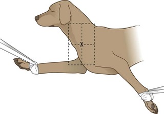
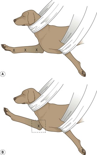
Procedure: Lateral spine (Fig. 6.1):
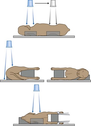
Figure 6.1 Positioning for lateral spine. (With permission from Lee R (ed) (1995) Manual of Small Animal Diagnostic Imaging 2e, BSAVA Gloucester, p 137.)
1. Action: Place the patient in right lateral recumbency.
Rationale: It is traditional to have the head to the left on the radiograph.
2. Action: Place supporting pads under the natural curves of the spine (i.e. the neck and lumbar spine).
Rationale: This support prevents these areas dropping down towards the table and keeps the spine in a level horizontal line.
3. Action: Place pads under the sternum and between the limbs.
Rationale: These prevent rotation, which will pull the spine out of its horizontal position.
4. Action: If the lower cervical spine is to be examined, pull the limbs caudally (Fig. 6.1).
Rationale: This ensures that the musculature of the shoulder does not overlie C6 and C7.
5. Action: If the cervical spine as a whole is to be examined, place a pad under the nose.
Rationale: This prevents rotation of the head. This should also be done if the whole spine is to be examined.
6. Action: Centre the primary beam (as indicated by the cross wires in the light-beam diaphragm) over the point of interest. Include muscle mass, but not fat and skin.
Rationale: Centring must be accurate and care must be taken to avoid covering too large an area in one view because divergence of the beam at the edges of the field will cause artificial narrowing of the intervertebral spaces. Aim to cover 3–4 intervertebral spaces in each view.
7. Action: If the entire spine is to be examined, ensure that each image overlaps with the ones on either side.
Rationale: By ensuring overlap a complete study of each vertebra and its associated intervertebral spaces can be achieved with a minimum of distortion.
8. Action: If the first film fails to identify an abnormality, take repeat films on either side of the initial film.
Rationale: To ensure that you have thoroughly examined the area of the spine.
NB Centring points for the whole spine are as follows:
Fewer films may be sufficient for cats and small dogs.
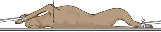
Procedure: Ventro-dorsal spine (Fig. 6.2):
1. Action: Place the dog in dorsal recumbency supported in a trough or by foam pads or sandbags.
Rationale: The spine must be positioned so that the sternum and spine are in the same vertical plane. It may be difficult to prevent rotation, particularly in deep-chested dogs. Remember that sandbags are radio-opaque.
2. Action: Extend the hind- and forelimbs and secure with ties.
Rationale: This prevents rotation and flexion of the lumbar spine.
3. Action: Extend the neck and hold in place with tape or a sandbag overlay. It may help to place a pad under the neck.
Rationale: This ensures that the spine is fully extended.
4. Action: Centre the primary beam (as indicated by the cross wires in the light-beam diaphragm) over the point of interest.
Rationale: Try to select the areas radiographed in the lateral view so that you have two planes per area of the spine, which makes location of the lesion much easier.
5. Action: If the entire spine is to be examined, ensure that each image overlaps with the ones on either side.
Rationale: By ensuring overlap a complete study of each vertebra and its associated intervertebral spaces can be achieved with a minimum of distortion.
6. Action: If the first film fails to identify an abnormality, take repeat films on either side of the initial film.
Rationale: To ensure that you have thoroughly examined the area of the spine.
NB Centring points for the whole spine are as follows:
Fewer films may be sufficient for cats and small dogs.
2 Head and neck
Imaging of the skull may be required for the investigation of trauma or of swellings related to infection or neoplasia, and of neurological signs associated with the CNS and the cranial nerves. The anatomy of the skull is complex and the interpretation of radiographs relies on accurate positioning.
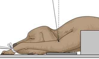
Procedure: Rostro-caudal view – open mouth: This is used to demonstrate the tympanic bullae, the foramen magnum, C1 and C2 and the atlanto-occipital joint.
1. Action: Place the animal in dorsal recumbency with the hard palate vertical to the cassette. Tip the nose backwards slightly past the vertical.
Rationale: This position ensures that the tympanic bullae are as close as possible to the cassette. Tilting the head ensures that the bones of the skull do not obscure the view of the bullae.
2. Action: Hold the mouth open to form a V shape (Fig 6.3) using tapes, or place an old needle case (with one end cut off to form a hole) between the teeth of the upper and lower jaws.
Rationale: This removes the mandible and maxilla from the area of interest.
3. Action: Orientate the primary beam towards the hard palate and centre it (indicated by the cross wires in the light-beam diaphragm) on the base of the tongue.
Rationale: In this position the tympanic bullae are located directly behind the base of the tongue.
4. Action: If the animal is intubated, remove the endotracheal tube just before exposure.
Rationale: The tube may be superimposed on the tympanic bullae.
Procedure: Rostro-caudal view – closed mouth: This is used to demonstrate the frontal sinuses, zygomatic arch and temporal region, and the sagittal crest. It is of less use in the cat as the conformation of the skull is different.
1. Action: Place the animal in dorsal recumbency with the hard palate vertical to the cassette.
Rationale: This position ensures that the frontal sinuses, zygomatic arch and temporal region, and the sagittal crest are all in line on the cassette.
2. Action: Wind a tape around the nose.
Rationale: To hold the jaw closed.
3. Action: Direct the primary beam at an angle of 5–10° to the vertical in a rostro-caudal direction.
Rationale: This enables an image of the structures to be seen on the radiograph.
Procedure: Ventro-dorsal view: The ventro-dorsal (VD) view is used for the examination of the tympanic bullae and the external auditory meatus on either side.
1. Action: Place the animal in dorsal recumbency.
Rationale: This ensures that the skull is as close as possible to the film.
2. Action: Extend the neck (Fig 6.4).
Rationale: Extension makes sure that the head is horizontal. This position may be quite difficult to hold because the sagittal crest tends to tilt the head to one side or the other.
3. Action: Place a pad under the neck.
Rationale: This forces the head back so that the hard palate is parallel to the cassette.
4. Action: Secure a tape around the upper canines and tie it to the table top (Fig. 6.4).
Rationale: This ensures that the hard palate remains in a horizontal plane.
5. Action: Place a right or left marker on the cassette beside the head as appropriate.
Rationale: It is important to be able to identify the location of a lesion or mass.
6. Action: Centre the beam (as indicated by the cross wires in the light-beam diaphragm) in the midline at a point halfway along the interpupillary line.
Rationale: This point may vary with the area to be examined.
7. Action: Collimate the beam to include the entire skull.
Rationale: If necessary, collimate more tightly over the area of interest.
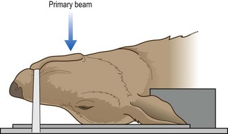
Procedure: Dorso-ventral view: The dorso-ventral (DV) view is used for examination of the ear and the temporo-mandibular joint.
1. Action: Place the animal in sternal recumbency with the neck extended (Fig. 6.5).
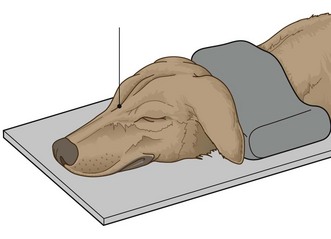
Figure 6.5 Dorso-ventral view of the skull. (With permission from Lee R (ed) (1995) Manual of Small Animal Diagnostic Imaging 2e, BSAVA Gloucester, p 17.)
Rationale: The head is now in a stable position. This is preferred to the VD position even though there is some magnification because of the distance of the skull from the cassette.
2. Action: Place a sandbag over the neck.
Rationale: This keeps the hard palate parallel to the cassette especially in deep-chested dogs.
3. Action: Place a right or left marker on the cassette beside the head as appropriate.
Rationale: It is important to be able to identify the location of a lesion or a mass.
4. Action: Centre the beam (indicated by the cross wires in the light-beam diaphragm) on a line midway between the eyes.
Rationale: This point may vary according to the point of interest.
Procedure: Lateral view of the skull: This is of limited value especially in visualizing the oral cavity as one side of the jaw is superimposed on the other.
1. Action: Place the animal in lateral recumbency.
Rationale: The animal will be completely stable in this position.
2. Action: Place foam pads under the nose and the mandible.
Rationale: This ensures that the sagittal plane of the skull is parallel to the cassette.
3. Action: Centre the primary beam (indicated by the cross wires in the light-beam diaphragm) midway between the ear and eye.
Rationale: This will provide a view of most structures on the head.
Procedure: Lateral oblique view: This is used to show masses or lesions identified in other views and to view the tympanic bullae or temporo-mandibular joints. It is also used to view the dental arcades (e.g. for the diagnosis of a malar abscess).
1. Action: Place the animal in lateral recumbency.
Rationale: This is the most stable position for this view.
2. Action: Tilt the head along its long axis and support with foam pads.
Rationale: This will separate each side of the head.
3. Action: Alternatively tilt the animal’s nose up by about 15° and support with pads.
Rationale: The aim of this view is to raise the lesion or mass so that it is on the ‘skyline’; the position will vary according to the location of the lesion.
4. Action: If viewing the teeth, place foam wedges under the appropriate arcade.
Rationale: Remember to keep the mandible or maxilla in a horizontal plane parallel to the cassette; foam wedges will help to do this. The side under investigation should be closest to the cassette.
5. Action: If necessary, open the mouth and hold it open with a dental gag or needle case between the teeth.
Rationale: This will prevent the mandible from obscuring the view of the upper arcades.
6. Action: Centre the beam (indicated by the cross wires in the light-beam diaphragm) on the point of interest (Fig. 6.6).
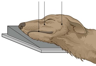
Figure 6.6 Lateral view of the skull. (With permission from Lee R (ed) (1995) Manual of Small Animal Diagnostic Imaging 2e, BSAVA Gloucester, p 17.)
Rationale: This will vary according to the case. If viewing a dental arcade, centre the beam half way along it.
NB This view can be varied according to what you want to investigate in more detail having identified a lesion in other positions.
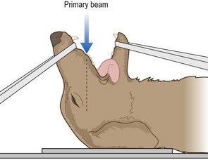
Procedure: Dorso-ventral intra-oral view: This is used for the investigation of the premaxilla, upper incisors, rostral portions of the maxilla and premolar teeth, and for the nasal cavity.
1. Action: The animal must be fully anaesthetized.
Rationale: The cassette is placed in the animal’s mouth – anaesthesia will prevent it chewing the film.
2. Action: Place the animal in sternal recumbency and extend the neck. Support with foam pads (Fig. 6.7).
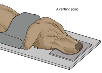
Rationale: The position of the head is straighter if the neck is extended.
3. Action: Place a sandbag over the neck.
Rationale: To prevent rotation of the head.
4. Action: The endotracheal tube should be tied to the lower jaw.
Rationale: To keep it in place and to allow correct placement of the cassette.
5. Action: Place a non-screen film above the tongue and the tube as far as possible into the mouth.
Rationale: Non-screen film will provide better definition, particularly of the maxillary arcades, but screen film in flexible oral cassettes may be used for the incisors.
6. Action: Place a left or right marker beside the head as appropriate.
Rationale: It is important to be able to identify the location of any lesions.
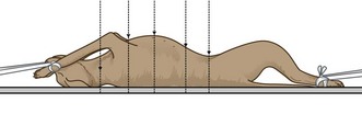
Procedure: Ventro-dorsal intra-oral view: This is used for investigation of the body of the mandible, the rostral parts of the horizontal rami of the mandibles and the mandibular incisor teeth.
1. Action: The animal must be fully anaesthetized.
Rationale: To enable accurate positioning and to prevent the animal chewing on the cassette placed in its mouth.
2. Action: Place the animal in dorsal recumbency and support it.
Rationale: Use a plastic trough and / or foam wedges to keep the body from tilting.
3. Action: Push the tongue firmly to one side or place it symmetrically in the centre of the oral cavity.
Rationale: To avoid any confusion when evaluating the radiograph.
4. Action: Use only radiolucent gags in the mouth.
Rationale: To prevent the image appearing on the radiograph.
5. Action: Position the endotracheal tube away from the point of interest.
Rationale: To prevent it interfering with the image.
6. Action: Place the cassette as far as possible into the mouth between the tongue and hard palate.
Rationale: Flexible oral cassettes (screen film) are used to enable the film to be pushed as far back in the mouth as possible. Non-screen film will provide better definition.
7. Centre the beam as follows:
• Action: The incisor teeth – at an angle of 20° to the vertical (Fig. 6.8) – i.e. aiming rostro-caudally.
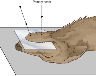
Figure 6.8 Ventro-dorsal intra-oral view. (With permission from Lee R (ed) (1995) Manual of Small Animal Diagnostic Imaging 2e, BSAVA Gloucester, p 24.)
Rationale: To prevent foreshortening and to allow full evaluation of the dental roots and alveoli.
• Action: The horizontal rami of the mandible – over the mid-point of a line drawn from the mandibular symphysis to the larynx (Fig. 6.8).
Rationale: The centring point will vary according to the point of interest.
Procedure: Ventro-dorsal open mouth oblique rostro-caudal view: This is used to investigate the nasal passages and allows better visualization of the more caudal regions than the dorso-ventral intra-oral view.
1. Action: The animal must be fully anaesthetized.
Rationale: To allow adequate relaxation and thus accurate positioning.
2. Action: Place the animal in dorsal recumbency with the head as straight as possible. Use a trough or wedges to hold the body in position without tilting to one side.
Rationale: If the body tilts it will tilt the head. This will lead to inequalities in the nasal cavities and may lead to a misdiagnosis.
3. Action: Open the mouth as widely as possible and prop open with a dental gag or a needle case between the caudal molars or the carnassials.
Rationale: This prevents the mandibles obscuring the view of the maxillae.
4. Action: Pull the tongue and the endotracheal tube to one side.
Rationale: To prevent them obscuring the view of the maxillae.
5. Action: Place the cassette under the head.
Rationale: So that the nasal cavities are as close as possible to the cassette thus preventing excessive magnification.
6. Action: Centre the primary beam (indicated by the cross wires in the light-beam diaphragm) on a point halfway along the length of the hard palate and collimate to include the whole hard palate.
Rationale: This will provide good visualization of the whole of both nasal cavities.
3 Thorax
Radiography of the thorax provides a guide to the diagnosis of many conditions because it allows examination of the lower respiratory tract, the lung tissue and the pleurae, the heart, the mediastinum, the diaphragm and the thoracic wall. Problems may occur because the chest wall and diaphragm are always moving and steps must be taken (e.g. reducing the exposure time) to minimize movement blur.
1. Action: Place the animal in right lateral recumbency.
Rationale: This is the conventional position for a thoracic radiograph because the heart lies in a more consistent position, there is more air-filled lung between the heart and the chest wall, which gives better cardiac detail, and the diaphragm obscures less of the caudal lung field.
2. Action: Extend the forelegs and secure with ties tied to cleats on the table or with sandbags.
Rationale: Extending the forelegs prevents the soft tissue mass of the shoulder girdle impeding the view of the thoracic contents.
3. Action: Place a pad under the sternum.
Rationale: To prevent rotation of the chest and ensure that it remains in the same horizontal plane as the spine. This prevents distortion of the thoracic structures.
4. Action: Place sandbags over the neck and the hindlegs.
Rationale: The hindlegs should be secure, but should not be tied as this leads to rotation of the chest.
5. Action: Centre the beam (as indicated by the cross wires on the light-beam diaphragm) midway between the sternum and spine and level with the caudal border of the scapula (approximately the 5th rib).
Rationale: This ensures that the primary beam coincides with the base of the heart.
6. Action: Collimate the beam to include the cranial thoracic inlet, the edge of the sternum, the thoracic spine and the full extent of the diaphragm.
Rationale: All parts of the lung will be included. In large breeds it may be necessary to cover the area with two overlapping films.
7. Action: Expose on inspiration.
Rationale: This ensures that the diaphragm is flattened, creating maximum space in the cavity for the organs. The lungs are fully inflated, which provides better contrast between the air in the lungs and the soft tissues.
NB It is good practice to take both right and left lateral views. A lesion may appear on one side only, masked by a lung lobe and may be missed on the other view.
Forced inspiration is preferable to natural inspiration as it provides better contrast. This can be achieved only in the anaesthetized patient and requires someone to squeeze the reservoir bag at the appropriate moment, necessitating his / her exposure to radiation. Consider the IRR 1999 and make sure the assistant is wearing protective clothing and a dosemeter and that it is not always the same person!
Procedure: Dorso-ventral thorax: This view is recommended for animals in respiratory distress but is less comfortable for animals with hindlimb injuries.
1. Action: Place the animal in sternal recumbency with the elbows symmetrically drawn outwards and gently pulled forwards – you may find it easier to place the animal in a trough (Fig. 6.9).
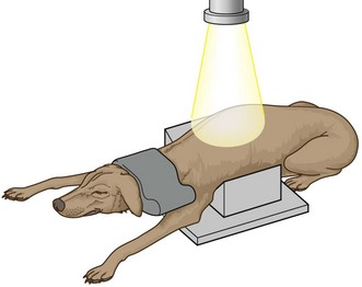
Figure 6.9 Positioning for dorso-ventral view of the thorax. (With permission from Lee R (ed) (1995) Manual of Small Animal Diagnostic Imaging 2e, BSAVA Gloucester, p 46.)
Rationale: This view allows the heart to lie in its normal position and is used for heart investigations. It is also used for conscious or sedated animals in respiratory distress as this allows them to breathe more easily. Drawing the elbows outwards prevents the muscles of the shoulder girdle from overlying the thoracic cavity.
2. Action: Support the chin on a foam pad.
Rationale: This keeps the head, neck and spine in a horizontal plane. If the animal is conscious it will be more comfortable.
3. Action: Place a sandbag over the neck (Fig. 6.9), making sure that it does not obscure the edge of the collimated area.
Rationale: To prevent movement. Sandbags are radio-opaque.
4. Action: Place a left or right marker as appropriate.
Rationale: To assist in the location of any lesions.
5. Action: Centre the beam (as indicated by the cross wires in the light-beam diaphragm) in the midline on the caudal border of the scapula.
Rationale: This ensures that the heart is in the centre of the image.
6. Action: Collimate the beam to include the skin edges, the thoracic inlet and the diaphragm.
Rationale: The image should include the caudal and cranial lung fields.
7. Action: Expose on inspiration.
Rationale: This ensures that the diaphragm is flattened, creating maximum space in the cavity for the organs. The lungs are fully inflated, which provides better contrast between the air in the lungs and the soft tissues (see additional notes above).
NB The radiographic image should be symmetrical and show the spine superimposed on the sternum in the midline.
Procedure: Ventro-dorsal thorax: This should be avoided in animals that are in respiratory distress because breathing may be made even more difficult. Animals with hindlimb injuries may be more comfortable.
1. Action: Place the patient in dorsal recumbency supported in a trough or by foam wedges (Fig. 6.10).
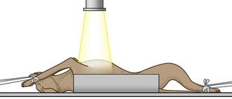
Figure 6.10 Positioning for ventro-dorsal view of the thorax. (With permission from Lee R (ed) (1995) Manual of Small Animal Diagnostic Imaging 2e, BSAVA Gloucester, p 46.)
Rationale: Care must be taken to avoid rotation. In this view the heart may rotate to one side and its size and shape may be distorted.
2. Action: Extend each foreleg separately and secure with a tie attached to cleats under the table or with a sandbag placed over each carpus.
Rationale: This prevents rotation. Do not place sandbags over the axillae as this is uncomfortable.
3. Action: The hindlegs may be extended or allowed to remain in a flexed position.
Rationale: Take care that the pelvis does not rotate to either side as this will tilt the thorax out of its central position.
4. Action: Place a left or right marker on the cassette as appropriate.
Rationale: It is important to be able to locate a lesion.
5. Action: Centre the primary beam (as indicated by the cross wires in the light-beam diaphragm) midway along the sternum and collimate to include the cranial thoracic inlet and the diaphragm / cranial abdomen.
Rationale: This should ensure that you include the whole thoracic cavity.
6. Action: Expose on inspiration.
Rationale: This ensures that the diaphragm is flattened, creating maximum space in the cavity for the organs. The lungs are fully inflated, which provides better contrast between the air in the lungs and the soft tissues (see additional notes above).
NB The radiographic image should be symmetrical and show the spine superimposed on the sternum in the midline.
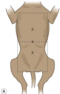
4 Abdomen
There are many indications for radiography of the abdomen, including investigation of the various parts of the alimentary tract, the kidneys and urinary tract, the reproductive tract and the associated parenchymatous organs such as the liver. The positioning of the patient is fairly simple, but accurate collimation and centring of the primary beam will provide your main guides to diagnosis. It is good practice to take two views of the abdomen (i.e. lateral and VD in particular); this will help you to identify the location of air within the abdomen – if it moves it is free in the peritoneal cavity; if it does not it is trapped within an organ.
1. Action: Place the animal in right lateral recumbency.
Rationale: Traditionally the animal is placed in right lateral recumbency but, as the abdomen is not the same on both sides, the right and left views will vary slightly. If time and money allow, you should take radiographs of both sides.
2. Action: Place a pad under the sternum.
Rationale: This provides support, which keeps the body in a horizontal plane.
3. Action: Extend the fore- and hindlimbs and secure them with sandbags or ties.
Rationale: To prevent movement. Remember to keep the sandbags out of the primary beam as they are radio-opaque.
4. Centre the primary beam (as indicated by the cross wires in the light-beam diaphragm) as follows:
• Action: Small dogs and cats – on a line from the 11th/12th rib to the iliac crest depending on the point of interest.
Rationale: The whole abdomen can be included on one film.
• Action: Large dogs – for the cranial abdomen, centre over the costal arch; for the caudal abdomen, centre midway between the last rib and the pelvic inlet.
Rationale: Take two overlapping films to radiograph the whole abdomen.
5. Action: Collimation should include the dorsal and ventral skin edges and the appropriate boundaries depending on size of patient and point of interest.
Rationale: The cranial border of the liver should always be included if the whole abdomen is to be examined.
6. Action: Expose on expiration.
Rationale: During expiration the diaphragm relaxes into a dome shape, providing the maximum amount of space for the abdominal organs.
Procedure: Ventro-dorsal abdomen: This is the preferred view for the examination of the abdomen. A DV may sometimes be used for contrast studies of the stomach.
1. Action: Place the patient in dorsal recumbency supported in a trough or with pads or sandbags (Fig. 6.11).
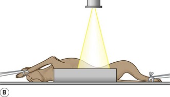
Rationale: Use of positioning aids prevents rotation of the body. The sternum and spine should be aligned vertically.
2. Action: Extend each foreleg cranially and secure with a tie attached to the cleats under the table or with a sandbag placed over each carpus.
Rationale: This prevents rotation. Avoid placing sandbags over the axillae as this will be uncomfortable.
3. Action: Extend the hindlimbs and secure with ties or sandbags.
Rationale: The hind limbs can be left untied but the body may rotate, especially in deep-chested breeds.
4. Action: Place a left or right marker on the cassette under the body.
Rationale: It is important to be able to locate any abnormalities.
5. Centre the primary beam (as indicated by the cross wires in the light-beam diaphragm) as follows:
• Action: Small dogs and cats – in the midline at the level of the umbilicus.
Rationale: The whole abdomen can be included on one film.
• Action: Large dogs – for the cranial abdomen, in the midline level with the last rib; for the caudal abdomen, midway between the last rib and the pelvic inlet.
Rationale: Take two overlapping films to radiograph the whole abdomen.
6. Action: Collimation should include the lateral skin edges and the appropriate boundaries depending on the point of interest.
Rationale: The cranial border of the liver should always be included if the whole liver is to be examined.
7. Action: Expose on expiration.
Rationale: During expiration the diaphragm relaxes into a dome shape, providing the maximum amount of space for the abdominal organs.
NB A VD view is useful to show the presence of air in the colon.
5 Appendicular skeleton
Radiography of the limbs and their girdles has always been the main use of x-rays in veterinary practice and there is a wide range of clinical indications for its use (e.g. fractures, lameness, deformities and the monitoring of inherited conditions such as hip dysplasia). As with other areas of radiography, to locate an abnormality accurately it is important to take at least two views of an area. Collimation should be as tight as possible and it is rarely necessary to include the whole limb.
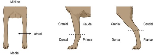
To describe the planes in which limb radiographs are taken, remember that views are described in the direction the beam enters and then leaves the limb and also remember to use the correct nomenclature: e.g above the carpus and tarsus – use the terms cranial and caudal (Cr/Cd); below the carpus – use the terms dorsal and palmar (D/Pa); below the tarsus – use the terms dorsal and plantar (D/Pl) (Fig. 6.12).
A The forelimb
Procedure: Shoulder – medio-lateral view: By centring correctly, this may be used to examine both the shoulder joint and the scapula.
1. Action: Place the animal in lateral recumbency making sure that the limb to be examined is closest to the cassette.
Rationale: This prevents magnification of the joint.
2. Action: Extend the head and neck and secure by placing a sandbag over the neck. Be careful not to interfere with normal respiration.
Rationale: This ensures that an endotracheal tube lying within the larynx and trachea is pulled away from the area of the shoulder. You may still have to partially withdraw the tube for a short period.
3. Action: Pull the affected leg cranially and ventrally and secure with a tie (Fig. 6.13).
Rationale: This ensures that the shoulder is not obscured by the cervical spine or the soft tissues of the other shoulder.
4. Action: Pull the opposing limb caudally and secure with a tie.
Rationale: This draws the soft tissues of the shoulder away from the shoulder under examination.
5. Action: Centre the beam (as indicated by the cross wires in the light-beam diaphragm) through the joint space of the shoulder.
Rationale: Palpate the greater tuberosity on the lateral aspect of the joint and go slightly caudal to it – this will give you the correct location.
6. Action: Collimate to include the proximal third of the humerus and the distal part of the scapula.
NB To view the whole scapula, centre the beam midway along the spine of the scapula. To view the humerus, centre midway between the shoulder and the elbow.
Procedure: Shoulder – cranio-caudal view: This is the best position for examining the shoulder joint or the scapula.
1. Action: Place the animal in dorsal recumbency and support in a trough or with sandbags (Fig. 6.14).
Rationale: This allows extension of the limb while preventing obstruction of the chest wall.
2. Action: Fully extend the limb to be examined cranially and secure with a tie.
Rationale: This will demonstrate the joint without the elbow overlying the area.
3. Action: Rotate the thorax until the limb is in the cranio-caudal position.
Rationale: This enables a true cranio-caudal position to be achieved.
4. Action: Centre the beam (as indicated by the cross wires in the light-beam diaphragm) over the acromion of the scapula.
Rationale: The acromion can be palpated on the lateral aspect of the shoulder joint. The joint should be in the centre of the radiograph and demonstrated without distortion.
5. Action: Collimation should include the proximal third of the humerus and distal part of the scapula.
NB To view the scapula, centre the beam midway between the acromion and the caudal part of the scapula blade.
Elbow – one of the reasons for examination of the elbow may be to screen for elbow dysplasia. This is a multifactorial condition manifesting as a variety of developmental disorders that may eventually progress to osteoarthritis. It may appear in a wide range of breeds, e.g. Basset Hound, Great Dane, Labrador and Golden Retriever, and, as there is a strong genetic component, the British Veterinary Association / Kennel Club (BVA / KC) have a scheme for screening dogs intended for breeding and their progeny.
Radiographs are submitted to a panel for grading and must be labelled with the KC number, the date and a left / right marker. Each elbow must be examined and the positioning is as described below. Radiographs that are positioned or labelled incorrectly will be returned by the scrutinizing panel.
Procedure: Elbow – medio-lateral view: By changing the centring of the primary beam, this position can also be used to achieve a medio-lateral view of any part of the distal extremity (Fig. 6.15).
1. Action: Place the animal in lateral recumbency with the limb to be radiographed closest to the cassette; for example, for the right elbow – place in right lateral recumbency (Fig. 6.15).
Rationale: This prevents distortion and magnification of the image.
2. Action: Pull the upper leg caudally and dorsally and secure with a tie.
Rationale: This pulls the limb and its associated tissue away from the area of interest.
3. Action: Extend the lower limb and, if necessary, place a foam pad under the olecranon, carpus and foot. The angle between the humerus and lower forelimb should be 110°.
Rationale: The pad will prevent rotation, allowing the limb to lie parallel to the cassette and producing a true medio-lateral view.
4. Action: Place a left or right marker on the cassette.
Rationale: It is important to identify which limb is being examined.
5. Action: Centre the primary beam (as indicated by the cross wires in the light-beam diaphragm) over the medial humeral condyle.
Rationale: This extended view is used to evaluate the cranial aspect of the radial head and the humero-radial joint space.
6. Action: Collimate to include the lower third of the humerus and the upper third of the lower forelimb.
NB The elbow should also be examined in flexion so that the angle between the humerus and lower forelimb is 45°. Centre on the medial humeral condyle and collimate as above. This view is used to show the anconeal process and the humeral epicondyles.
You may be able to include both elbows on one film, remembering to cover one side with a lead sheet while exposing the other side. This is acceptable for the BVA / KC scheme.
Procedure: Elbow – cranio-caudal view: This is a difficult position to achieve and steps must be taken to prevent rotation. It is no longer required as part of the BVA / KC scheme for elbow dysplasia.
1. Action: The animal is placed in sternal recumbency supported by sandbags under the chest on the side not under examination.
Rationale: It is important to stop the animal from slipping sideways – deep-chested breeds may need more support. Sandbags are radio-opaque so take care not to obscure the image.
2. Action: Extend the forelimb to be examined and secure with ties.
Rationale: You may need to slightly tilt the thorax towards the limb to keep the latter comfortably extended. You may also need to turn the head and neck away from the limb under examination, which allows a clearer view of the elbow.
3. Action: Centre the primary beam (as indicated by the cross wires in the light-beam diaphragm) on the radio-humeral joint at an angle of approximately 15° to the vertical.
Rationale: Palpate the humeral condyles to locate the distal end of the humerus (Fig. 6.16).
1. Action: Place the animal in dorsal recumbency with its body supported in a trough or with sandbags.
Rationale: It is important to keep the animal straight.
2. Action: Extend the limb to be examined caudally and secure with a tie.
Rationale: This will bring the elbow joint into the correct plane for examination.
3. Action: Centre the primary beam (as indicated by the cross wires in the light-beam diaphragm) vertically over the radio-humeral joint.
Rationale: See Figure 6.17.
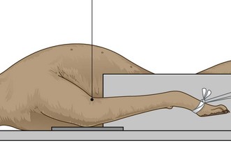
Figure 6.17 Positioning for the cranio-caudal view of the elbow in dorsal recumbency. (With permission from Lee R (ed) (1995) Manual of Small Animal Diagnostic Imaging 2e, BSAVA Gloucester, p 117.)
NB This position is not recommended for use in the BVA / KC scheme.
Procedure: Dorso-palmar view of the forefoot:
1. Action: Place the animal in sternal recumbency so that the foot under investigation is parallel to the cassette.
Rationale: The animal will need some form of support (e.g. sandbags), but unless the dog is deep chested it should be relatively stable in this position.
2. Action: Extend the forelimb so that it is straight.
Rationale: There may be a tendency for the limb to rotate inwards so, to prevent this, rotate the trunk slightly towards the limb being examined.
3. Action: Centre the primary beam (as indicated by the cross wires in the light-beam diaphragm) at the level of the carpal joint or the metacarpus or digits.
Rationale: Positioning is the same but the different areas can be examined by centring over the point of interest.
4. Action: Collimation should be as tight as possible and centred on the point of interest.
Rationale: Tight collimation reduces scatter, but including the joint above and below or a small area of bone above and below may aid your diagnosis.
NB It is not a good idea to radiograph both distal forelimbs at the same time as there is often a degree of rotation in one limb or both.
Medio-lateral view of the carpus and forefoot – this can be achieved by following the guidelines described under medio-lateral view of the elbow (Fig. 6.15). Using the same positioning the carpus can also be examined in the following positions:
• Flexed position – used to check for articular fractures. Hold the limb in flexion using a tie around the joint.
• Extended stressed position (i.e. as it would be when weight bearing) – used to assess ligamentous damage. This requires manual positioning and attention must be paid to radiation safety.
B The hindlimb
Procedure: Pelvis – lateral view:
1. Action: Place the animal in right or left lateral recumbency as appropriate.
Rationale: This is the only way of providing a true lateral projection of the pelvis.
2. Action: Place pads between the hindlimbs.
Rationale: This prevents rotation of the pelvis.
3. Action: Centre the primary beam (as indicated by the cross wires in the light-beam diaphragm) on the greater trochanter of the femur.
Rationale: This ensures that the wings of the ilium and the acetabulum are visible.
Procedure: Pelvis – ventro-dorsal view: This is the standard view for the assessment of the hips and pelvis and is the view required by the BVA / KC scheme for the assessment of hip dysplasia. It is important to make sure that the radiograph is correctly positioned as those that are not will be returned. The radiograph must also be correctly labelled with the dog’s KC number, the date of radiography and a right and / or left marker.
1. Action: Place the animal in dorsal recumbency, ensuring that the body is straight (Fig. 6.18).
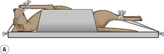
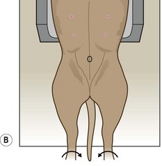
Figure 6.18 (A, B) Positioning for ventro-dorsal pelvis for assessment of hip dysplasia. (Part B with permission from Lee R (ed) (1995) Manual of Small Animal Diagnostic Imaging 2e, BSAVA Gloucester, p 124.)
Rationale: This may be helped by the use of a trough or sandbags placed on either side of the upper abdomen. If the upper body is straight the pelvis should be straight. If the pelvis rotates, place a pad under the lower hip.
2. Action: Extend the hindlegs caudally so that the hips and hocks are fully extended. Secure with ties at the hocks.
Rationale: This will further ensure that the pelvis is straight.
3. Action: Holding the hindlegs separately, one in each hand, rotate medially so that the femurs lie parallel to each other and the patellae are centred over the distal femurs, pointing to the ceiling (Fig. 6.18).
Rationale: Rotating the femurs medially ensures that each femoral head sits deeply in the appropriate acetabulum. If correctly positioned the hindfeet should be turned slightly medially.
4. Action: Hold the femurs together by placing a tie or sticky tape around the level of the mid-femurs.
Rationale: This ensures that the limbs remain in this position.
5. Action: If necessary place another tie or sticky tape around the level of the mid-tibia.
Rationale: This may be necessary in larger dogs.
6. Action: Place a left / right marker as appropriate on the cassette.
Rationale: This is a requirement of the BVA / KC scheme and it is important to be able to locate any abnormality.
7. Action: Centre the primary beam (as indicated by the cross wires in the light-beam diaphragm) in the midline over the pubic symphysis, which can be palpated.
Rationale: This should provide equal detail on either side of the midline.
8. Action: Collimate the beam to include the wings of the ilium and the proximal half of the femurs.
Rationale: This should demonstrate the entire pelvic girdle and both hip joints.
9. Action: Make sure that your label falls within the collimated area.
Rationale: The scrutineers of the radiographs must be able to identify the owner / animal under examination.
NB If the animal is positioned correctly then the obturator foramina will be of equal size on the resulting radiograph; if the animal is lying crookedly then one will appear larger than the other – the animal will be tilted towards the smaller side.
When radiographing an animal with a suspected pelvic fracture, allow the legs to relax in a normal abducted position – this is known as the ‘frog leg’ position.
Procedure: Stifle – medio-lateral view:
1. Action: The animal is placed in lateral recumbency with the stifle to be examined lying closest to the cassette.
Rationale: This prevents distortion and magnification of the image.
2. Action: Draw the upper limb cranially and secure with ties.
Rationale: This prevents the bones and soft tissues of the limb obscuring the limb under examination.
3. Action: Allow the lower limb to lie in a neutral position on the cassette – that is, neither flexed nor extended (Fig. 6.19).
Rationale: This position will provide enough diagnostic detail.
4. Action: If the leg begins to rotate, place a foam pad under the caudal aspect of the hock.
Rationale: This should provide sufficient support to prevent rotation.
5. Action: Place a left / right marker as appropriate.
Rationale: It is important to be able to locate any abnormalities.
6. Action: Centre the primary beam (as indicated by the cross wires in the light-beam diaphragm) over the distal femoral condyle.
NB To view the femur, centre the primary beam midway between the hip and stifle.
To view the hock, centre the primary over the tibio-tarsal joint.
Procedure: Stifle – cranio-caudal view:
1. Action: Place the animal in dorsal recumbency supported in a trough or with sandbags.
Rationale: To prevent the animal tipping over to one side or the other.
2. Action: Rotate the body slightly away from the side under examination.
Rationale: This will put slight tension on the limb when it is balanced by the tie around the limb to be examined.
3. Action: Extend the limb caudally and secure with a tie (Fig. 6.20).
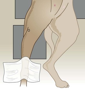
Figure 6.20 Positioning for cranio-caudal view of the stifle. (With permission from Lee R (ed) (1995) Manual of Small Animal Diagnostic Imaging 2e, BSAVA Gloucester, p 128.)
Rationale: This will keep the limb in the correct position.
4. Action: Place a left / right marker on the cassette.
Rationale: It is important to be able to locate any abnormality.
5. Action: Centre the primary beam (as indicated by the cross wires in the light-beam diaphragm) over the patella and collimate to include half of the femur and half of the tibia.
NB A caudo-cranial view of the stifle can be achieved by placing the animal in sternal recumbency and reduces magnification of the joint.
To view the tibia, centre the primary beam midway between the stifle and the hock.
To achieve a dorso-plantar view of the hock, centre the primary beam over the tibio-tarsal joint.
Procedure: Hindfoot – medio-lateral view:
1. Action: The animal is placed in lateral recumbency with the foot to be examined lying closest to the cassette.
Rationale: This prevents distortion and magnification of the image.
2. Action: Draw the upper limb cranially and secure with ties.
Rationale: This prevents the bones and soft tissues of the limb obscuring the limb under examination.
3. Action: Place the foot to be examined on the cassette and secure on its side using a tie.
Rationale: The beam is to enter on the medial side and exit laterally.
4. Action: If the leg begins to rotate place a foam pad under the caudal aspect of the hock.
Rationale: This should provide sufficient support to prevent rotation.
5. Action: Place a left / right marker as appropriate.
Rationale: It is important to be able to locate any abnormalities.
6. Action: Centre the primary beam (as indicated by the cross wires in the light-beam diaphragm) over the metatarso-phalangeal joints.
Dorso-plantar view of the hindfoot – follow positioning guidelines for the cranio-caudal view of the hock, but centre the beam over the metatarso-phalangeal joints.
Use of contrast media
Contrast media are substances that will enhance the radiographic contrast in areas that would otherwise be difficult or impossible to see on a normal plain radiograph. Their use allows the assessment of size, shape and position of an organ and in some cases they may be used to monitor the function as well.
Contrast media can be divided into two groups:
1. Positive contrast – these contain elements that have a high atomic number and are able to absorb x-rays, thus creating a white image on the resulting radiograph. The substances commonly used in veterinary medicine are:
• Barium sulphate – this is a white inert, non-toxic, tasteless substance that is available as a powder, a colloidal suspension or a paste. It is not absorbed by the body so must be used only by the oral route where it is excreted in the faeces. If it reaches the peritoneum (e.g. through a perforation) or is inhaled accidentally during administration it will result in the formation of granulomatous lesions that remain for life.
• Water soluble iodine preparations – these are the most common types of contrast media and come in many forms designed for different clinical situations. They are presented as clear liquids, but appear white on a radiograph. As they are water soluble they may be administered intravenously and they are rapidly excreted by the kidneys – one of their main uses is in urography. They are less commonly used in the digestive tract as they are bitter to taste and produce poorer contrast than barium; however, iodine is recommended if a perforation is suspected as it will be absorbed by the blood stream if it reaches the peritoneum.
2. Negative contrast – this involves the use of gases (e.g. atmospheric air, carbon dioxide). These have a low specific gravity and absorb very few x-rays therefore appearing black on a radiograph. They are commonly used to highlight hollow organs such as the stomach and bladder, but mucosal detail is poor. The gas is physically excreted or is absorbed by the blood stream.
Double contrast – this is a technique that combines both types of contrast media and is used to visualize the lining mucosa of hollow organs such as the bladder. It also avoids the masking of filling defects, such as may be caused by a foreign body in the stomach or calculi in the bladder, by dense positive contrast media.
A Alimentary tract
Investigation of the alimentary tract requires the use of barium sulphate in its appropriate form. With the exception of barium enemas, the patient should not be anaesthetized as this will interfere with normal gut physiology. If the patient is difficult, sedation with acepromazine may be used as this has the least effect on intestinal motility and it may make positioning easier.
If the procedure is elective the patient should be starved for 24 hours to empty the tract as much as possible and an enema should be administered, particularly if a barium enema is to be performed. Starvation is not essential and barium may be used in non-elective procedures.
Care must be taken to avoid the patient aspirating barium during its administration. This is a particular risk when investigating swallowing disorders and may lead to aspiration pneumonia. Never use barium in a patient suspected of having a gastric or intestinal perforation.
Procedure: Use of barium in the examination of the alimentary tract (Fig. 6. 21):
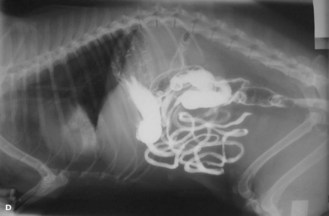
Figure 6.21 Use of barium to highlight the alimentary tract. Barium is visible in the stomach, the small intestine and has begun to reach the colon and rectum – taken 6.5 hours after administration.
1. Action: Prepare the barium away from the preparation room and the patient. Ready-made barium may be used.
Rationale: Barium may be administered as a sticky paste (e.g. for oesophageal studies), as a liquid (e.g for a barium series) or mixed with a small amount of food to encourage the patient to eat it. Do not prepare the mixture close to the x-ray table as it may contaminate the table or the patient.
2. Action: Ensure the patient is prepared appropriately.
Rationale: This will save time when the patient is presented. Good preparation prevents artefacts on the radiograph.
3. Action: Take plain radiographs before the barium is administered.
Rationale: These can be used for comparison with the contrast studies. In some cases the barium may mask some diagnostic features.
4. Action: Entice the animal to eat the barium preparation. Mixing it with food is easier, but if it is in liquid form it may have to be syringed into the mouth. Avoid getting barium on the fur.
Rationale: Use of food allows the natural eating and swallowing process to be observed. Barium on the fur creates a ‘paintbrush’ affect or spots on the resulting radiograph.
5. Action: If performing a barium swallow for examination of the oesophagus, use food mixed with barium and make an exposure of the oesophageal / thoracic area in right lateral recumbency within 2–3 minutes.
Rationale: Food takes 15–30 seconds to pass down the oesophagus into the stomach so an exposure must be made quickly. Any barium left in the oesophagus will line the mucosa and highlight any abnormalities.
6. Action: If you are performing a barium series (i.e. several radiographs taken at intervals) to follow the barium through the alimentary tract, give approximately 5 ml/kg of liquid barium (Fig. 6.21).
Rationale: A large volume is needed to prevent dilution as it passes down the tract.
7. Action: If performing a barium enema, the barium must be as liquid as possible. Introduce the barium into the rectum using a catheter by retrograde filling (Fig. 6.22). Air can be introduced to achieve double contrast.
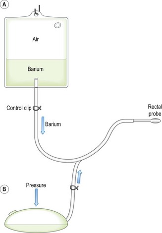
Figure 6.22 Barium enema bag. In position A, the barium flows under gravity into the colon. In position B, barium empties from the colon into the bag and then pressure on the bag will distend the colon with air for the double contrast effect.
Rationale: Barium is used to outline the mucosa of the colon and the image can be enhanced by air. This is a messy procedure – avoid contaminating the fur.
8. Action: Position the patient correctly to examine the appropriate part of the alimentary system, centring the primary beam and collimating accurately.
Rationale: The most common positions will be lateral and VD / DV views of the thorax and abdomen. Incorrect positioning may miss the abnormality or alter the pathology of an organ.
9. Action: Increase the kilovoltage above that used for a plain radiograph.
Rationale: This ensures that the edges of the barium are clearly delineated which aids interpretation of the radiograph.
10. Action: Always take four views for a full evaluation – these should be right and left lateral and DV and VD. Remember to use a left / right marker.
Rationale: This enables accurate location of the abnormality. The appearance of these radiographs will vary as barium will follow gravity and flow into the dependent areas and any gas will rise into the non-dependent areas.
11. Action: If examining the stomach, use air to achieve a double-contrast gastrogram.
Rationale: A thin layer of barium will highlight the gastric mucosa.
12. Action: If performing a barium series, take radiographs every 15 minutes until barium enters the colon.
Rationale: This is used to study gastric motility and emptying time and to identify the presence and location of foreign bodies or tumours. Gastric and intestinal motility can be truly assessed only using fluoroscopy.
13. Action: It may be necessary to make an exposure 24 hours after the original administration of barium.
Rationale: Remaining barium may stick to and highlight any abnormalities not previously identified.
B Urinary tract
Water soluble iodine preparations are used to study the upper urinary tract. As these are administered intravenously, taste bitter and may cause nausea the patient should be deeply sedated or anaesthetized, which also aids more accurate positioning. Perivascular iodine may also be irritant.
Procedure: Intravenous urography for examination of the kidneys and ureters (Fig. 6.23):
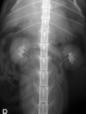
Figure 6.23 Use of water soluble iodine to highlight the urinary tract – taken 5 minutes after i.v. administration.
1. Action: The patient should be anaesthetized and given an enema.
Rationale: The presence of faeces in the colon may mask the view of the kidneys and ureters and may push the kidney into an abnormal position.
2. Action: Take plain radiographs in right lateral and ventro-dorsal recumbency, centred on the umbilicus.
Rationale: These views will demonstrate all of the urinary tract and can be used for comparison with the contrast radiographs.
3. Action: Using a urinary catheter, empty the bladder. Introduce a small amount of air into the bladder.
Rationale: It is always a good idea to collect a urine sample while you are emptying the bladder as you may need to analyse it later. Urine must be removed as it will dilute the contrast medium. Air in the bladder produces a clearer view of the ureters and the neck of the bladder.
4. Action: Place the animal in dorsal recumbency supported in a trough.
Rationale: This enables serial radiographs to be taken without disturbing the animal. Lateral radiographs can be taken when adequate opacification of the kidneys and tract has taken place.
5. Action: Administer the iodine preparation, which has been previously warmed, via the cephalic vein.
Rationale: The preparation is warmed to reduce the viscosity, which makes intravenous injection much easier.
6. There are two techniques for the administration of iodine and they depend on the reason for the contrast study:
• Action: Rapid bolus of a low volume.
Rationale: Rapid bolus – used for examination of the kidneys and ureters.
• Action: Slow infusion of a high volume.
Rationale: Slow infusion – used for incontinence and for ureteric problems.
7. Action: Bolus administration: using 300–400 mg iodine/ml conc. at a dose of 850 mg/kg body weight (approximately 1 ml/kg). Administer as rapidly as possible and take radiographs as soon as the injection is completed. Take serial radiographs at 1, 5, 10, 15 and 20 minutes.
Rationale: The iodine is excreted by the kidneys and will appear within the renal parenchyma within a few minutes (Fig. 6.23). Opacity increases as the process continues and iodine enters the bladder.
8. Action: Infusion administration: using 150–200 mg/ml iodine concentration at a dose of 1200 mg/kg body weight (approx. 8 ml/kg); may be diluted with dextrose or saline and given via an intravenous catheter over a period of 10–15 minutes. Take radiographs at 5, 10 and 15 minutes after the start of the infusion. Both VD and lateral views can be taken.
Rationale: The iodine is excreted by the kidneys and will appear within the renal parenchyma within a few minutes. Opacity increases as the process continues and iodine enters the bladder.
NB The rapid bolus technique may be used to investigate the bladder when radiographs may be taken 30 minutes after administration of the iodine. Rolling the patient from side to side will ensure thorough mixing of the contrast with any urine in the bladder. The results are not as informative as retrograde methods.
Procedure: Cystography – examination of the bladder using contrast material:
1. Action: The patient should be anaesthetized or deeply sedated and given an enema.
Rationale: The presence of faeces in the colon may alter the position of the bladder. A general anaesthetic will aid positioning and ensure radiation safety. The technique can be performed in conscious animals as it is not necessarily painful, but catheterization may cause the urethra to constrict and this should be noted when the radiograph is evaluated.
2. Action: Place the patient in right lateral recumbency and take a plain radiograph centred on the neck of the bladder and collimated to include the entire bladder.
Rationale: This can be used to compare with the contrast radiographs.
3. Action: Introduce a urinary catheter into the bladder and drain the urine. Leave the catheter in place.
Rationale: Do not use a rigid catheter in bitches as this distorts the neck of the bladder and may cause damage during positioning. It is a good idea to save some of the urine for analysis.
4. There are three techniques for visualizing the bladder using contrast media. Each has advantages and disadvantages:
• Action: Pneumocystogram – using room air.
Rationale: Overinflation may cause damage. Maintaining inflation may be difficult. Inadequate inflation and thickening of the bladder wall may mimic pathological changes. Used to detect the presence of calculi.
• Action: Positive contrast – using 20% contrast iodine.
Rationale: Good mucosal detail, but contrast may obscure lesions or calculi.
• Action: Double contrast – using air and iodine.
Rationale: Good for mucosal detail, for assessing the thickness of the bladder wall and for highlighting lesions or calculi.
5. Action: Pneumocystogram – with patient in right lateral recumbency introduce room air into the empty bladder using a syringe attached to the catheter and a three-way tap at a rate of approximately 10 ml/kg.
Rationale: The bladder should feel moderately distended when the abdomen is palpated. Take care not to overinflate. The bladder will appear as a dark mass in the caudal abdomen.
6. Action: Positive contrast – introduce dilute iodine at a rate of 10 ml/kg body weight into the empty bladder. Total volume will be between 50 and 300 ml depending on the size of the animal.
Rationale: The bladder appears as a white mass in the caudal abdomen.
7. Action: Double contrast – using 150 mg/ml iodine concentration, introduce 2–15 ml into the empty bladder. Gently roll the patient from side to side. Inflate the bladder with air until it feels taut.
Rationale: Rolling ensures that the mucosa is coated by the contrast material. The bladder mucosa will appear as a thin white line whereas the lumen appears black with a shadow of residual contrast in the centre.
8. Action: In all cases a lateral radiograph should be taken as soon as the contrast material has been introduced.
Procedure: Retrograde urethrography for examination of the urethra using positive contrast in the male:
1. Action: The patient should be anaesthetized or sedated and given an enema.
Rationale: The presence of faeces in the colon may mask the view of the kidneys and ureters and may push the kidney into an abnormal position. Sedation may be used in more cooperative animals. The procedure can be done in conscious animals, but it may cause the urethra to constrict and this should be taken into consideration when assessing the radiograph.
2. Action: Place the patient in right lateral recumbency and take a plain radiograph centred on the neck of the bladder and collimated to include the entire bladder.
Rationale: This may indicate any lesions that are later masked by the contrast material.
3. Action: Using a urinary catheter, empty the bladder and remove the catheter.
Rationale: The presence of urine in the bladder will dilute the contrast material. It is a good idea to save some of the urine for analysis.
4. Action: Select a Foley catheter of an appropriate size and flush it with contrast material before it is inserted.
Rationale: This flushes air out of the catheter. If air is present in the catheter when it is inserted the air may appear to be in the urethra and affect the diagnosis.
5. Action: Place the patient in right lateral recumbency.
Rationale: This is the most comfortable position for the patient and provides easy access to the penis and urethra.
6. Action: Gently insert the Foley catheter into the proximal part of the penile urethra and inflate the cuff.
Rationale: Inflating the cuff prevents backflow of contrast material out of the urethra.
7. Action: Using 150 mg/ml iodine conc. inject 5–15 ml slowly up the catheter.
Rationale: The addition of K-Y® jelly to the contrast material will increase the degree of urethral distension and may produce a better image.
8. Action: While you continue to inject the iodine take a lateral radiograph – take two radiographs, one with the hindlimb pulled caudally to show the penile urethra and the other with the hindlimb pulled cranially to show the ischial arch.
Rationale: Taking the radiograph while you inject the contrast ensures that not too much escapes into the bladder. Leakage of contrast from the opening of the penis may be prevented by occluding the end with your hands. Remember to protect yourself from scattered radiation by wearing a lead apron and either covering your hands with a lead sheet or wearing lead gloves.
NB If the prostatic urethra is to be examined, use a urinary catheter to introduce the contrast material further up the urethra – the tip should lie just distal to the prostate gland. This technique can also be used to identify the presence of ectopic ureters.
Procedure: Retrograde vaginourethrography for examination of the vagina and urethra using positive contrast in the female:
1. Action: The patient should be anaesthetized and given an enema.
Rationale: The use of Allis tissue forceps later on in the procedure is painful. The presence of faeces in the colon may alter the position of the bladder or urethra.
2. Action: Place the patient in right lateral recumbency and take a plain radiograph centred on the neck of the bladder and collimated to include the entire bladder.
Rationale: This may indicate any lesions that are later masked by the contrast material.
3. Action: Using a urinary catheter, empty the bladder and remove the catheter.
Rationale: The presence of urine in the bladder will dilute the contrast material. It is a good idea to save some of the urine for analysis.
4. Action: Select a Foley catheter of an appropriate size and flush it with contrast material before it is inserted.
Rationale: This flushes air out of the catheter. If air is present in the catheter when it is inserted the air may appear to be in the vestibule and affect the diagnosis.
5. Action: Place the patient in right lateral recumbency.
Rationale: This is the most comfortable position for the patient and provides easy access to the vagina and vestibule.
6. Action: Insert the Foley catheter through the vulval lips and into the vestibule and inflate the cuff.
Rationale: Inflating the cuff prevents backflow and leakage of the contrast material.
7. Action: Hold the catheter in place and attach a pair of Allis tissue forceps across the vulval lips.
Rationale: This prevents loss of the contrast material but can be painful in a conscious bitch.
8. Action: Using 150 mg/ml iodine concentration, inject 1 ml/kg body weight slowly up the catheter.
Rationale: The contrast will fill the vagina as far cranially as the cervix as well as the urethra. The contrast material enters the vagina under pressure and care must be taken not to overfill the vagina and urethra as rupture can occur.
9. Action: Stand away from the patient and take a lateral radiograph.
Rationale: If it is necessary to prevent further leakage of contrast material, you can occlude the vulval lips with your hands. Remember to protect yourself from scattered radiation by wearing a lead apron and either covering your hands with a lead sheet or wearing lead gloves.
Diagnostic ultrasound
Diagnostic ultrasound uses sound waves with a frequency of 2–10 MHz, which is much higher than the normal range audible to the human ear (20 kHz) and those used for therapeutic ultrasound (1 MHz).
The sound waves are produced from and received by a transducer containing crystals. These have piezo-electric properties so that when a voltage is applied to them they deform and emit characteristic high frequency sound waves – this is the inverse piezo-electric effect. The transducer produces regular short pulses of sound that pass through the body tissues. The returning sound or echoes are picked up by the same crystals, which deform again producing electrical signals – this is the piezo-electric effect. The signals are analysed according to their strength and the depth of tissue from which they have originated and this is displayed as an image on the screen.
When the transducer is applied to the skin, the ultrasound waves pass through the tissues. Each tissue has a different acoustic impedance or resistance to the sound waves and when the sound waves reach a boundary or acoustic interface between two tissues they may respond in one of two ways depending on the type of tissue. They may:
• Be reflected back again to be picked up by the transducer – this occurs when the acoustic impedance is great (e.g. air / soft tissue or bone / soft tissue).
• Continue deeper into the tissues – this occurs when the acoustic impedance is small (e.g. soft tissue / soft tissue).
As the sound waves travel through the tissues they become weaker or attenuated owing to a combination of reflection, absorption and scatter.
Image display modes
• A mode (amplitude mode) – this is rarely used nowadays as it provides limited information about the tissue boundaries. It uses a single fixed beam of ultrasound and the returning echoes are shown as peaks along a horizontal line (Fig. 6.24).
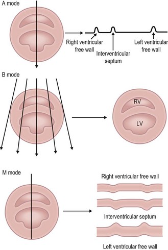
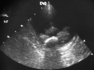
• B mode (brightness mode) – this is the most common type. Uses multiple beams of ultrasound and the returning echoes from each beam are analysed. Each dot on the screen represents a returning echo, its position indicates its origin and its brightness its strength. This information allows a two-dimensional cross section to be produced, which represents a slice through the tissues under examination. The image is constantly updated so that movement (e.g. the heart beating) can be observed – known as real-time scanning (Fig. 6.24).
• M mode (motion mode) – this shows movement of structures on a frozen image and is mainly used for echocardiography. A single scan-line is selected from the B-mode image. Echoes are represented as a vertical line on the left of the screen as dots. The distance of the dot along the line represents the depth of origin and the brightness represents the strength. The image is constantly updated (Fig. 6.24).
Types of transducer
• Linear array – 60–256 crystals are arranged in a line and are activated sequentially. It produces a wide rectangular field of view but requires a relatively large area of contact, which is difficult when examining thoracic and cranial abdominal structures in small animals.
• Curved linear array – this has a convex scanning surface so requires a smaller area of contact.
• Sector – this is a single or a small number of crystals producing a fan-shaped field of view. Does not allow good visualization of superficial structures, but it requires only a small area of contact so is most likely to be used in small animals (Fig. 6.25).
Other types of transducer are being developed.
Terminology
• Hyperechoic or echogenic – bright echoes that appear white. These are produced by highly reflective acoustic interfaces (e.g. gas, collagen and bone).
• Hypoechoic or echopoor – sparse echoes that appear grey. These are produced by acoustic interfaces that have intermediate reflection or transmission (e.g. soft tissues).
• Anechoic or echolucent – no returning echoes so they appear black. These represent complete transmission of ultrasound through the tissue (e.g. fluid).
Procedure: Basic examination technique: Use of diagnostic ultrasound is a non-invasive painless procedure that is well tolerated by most animals. It can usually be administered to fully conscious patients, although its use for guiding fine or biopsy needles may require sedation or general anaesthesia. There have been no reports of adverse clinical effects in the patient or in the personnel involved in its use.
1. Action: Place the patient on an examination table in a position that provides sufficient access to the area under examination.
Rationale: This may mean that the patient may remain standing or lying in lateral or dorsal recumbency. If the patient feels secure and comfortable it will be less likely to struggle.
2. Action: Select an appropriate part of the body for examination.
Rationale: Choose an area of skin over the point of interest and where the depth of tissue that has to be crossed is minimal.
3. Action: Avoid choosing a site where bone or gas-filled structures lie between the skin and the point of interest.
Rationale: Both bone and gas will block the ultrasound beam and may affect image quality or impair visualization of deeper tissues.
4. Action: Clip the skin and clean with surgical spirit.
Rationale: Fur must be removed to ensure good contact between the transducer and the skin. Surgical spirit is used to remove grease and dirt.
5. Action: Apply liberal quantities of acoustic or coupling gel to the transducer and the skin.
Rationale: This ensures that there is good contact between the transducer and the skin; it is more important to apply gel to the skin than it is to apply it to the transducer. Any other material (e.g. air or dirt) will create another acoustic interface, which may affect the image. Concentric white lines on the resulting image indicate poor contact and the site should be prepared again.
6. Action: Apply the transducer to the skin in the prepared area moving it around as necessary.
Rationale: The strength of the returning echo depends on the nature of the tissues and the angle of the interface relative to the sound beam.
Endoscopy
Endoscopy was originally developed as a technique for looking inside body cavities, but modern equipment also allows the recording of findings, the gathering of biopsy samples and performing minor surgical procedures.
There are two types of endoscope, rigid and flexible, which refer to their relative ability to bend within cavities. Both use a light source, which illuminates the cavity, and the resulting image is transmitted back to the operator. Endoscopes are expensive, delicate pieces of equipment and they should be treated with care.
• Rigid endoscopes – use is limited to sites lying in a straight line (e.g. nasal cavity, urethra, joints, ears) and are particularly used in large animals such as horses. Rigidity aids insertion and they consist of a relatively simple hollow insertion tube with a light source and a facility for viewing the image.
• Flexible endoscopes – of more use in small animals. They make use of fibreoptic technology, which relies on the fact that light can travel down a bendable fibre by repeated total internal reflection (TIR) exiting as a single spot of light. The fibre tubes are grouped together in image bundles that have the individual fibre faces fixed in an identical pattern (i.e. they are coherent). This ensures that the image transmitted is the same in each fibre, creating an accurate picture of the area under examination. Breakage of any of the tubes creates a black dot or area, which ruins the image. They produce a satisfactory image quality that is limited by the diameter and thus number of fibres in the bundle – narrower endoscopes have a limited amount of illumination. They are more portable and of moderate cost.
Video endoscopes are now available that allow the image to be relayed on a screen. The image quality is excellent and is improving all the time. The system allows several people to observe the process, but the equipment is less portable and is expensive.
Endoscopy is minimally invasive but there is the risk of harm to the patient (e.g. perforation leading to peritonitis, mediastinitis or a tension pneumothorax, airway irritation, infection, haemorrhage) or damage to the equipment (e.g. broken fibres, biting by patient, which may damage the insertion tube cover).
Common endoscopic procedures include:
• Examination of the upper and lower gastrointestinal tracts (proctoscopy or colonoscopy) (Fig. 6.26)
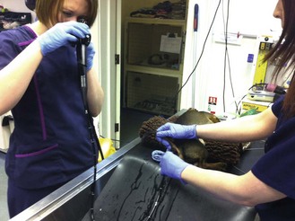
The endoscopic image can be difficult to interpret and it is possible to miss lesions. As with many techniques, practice makes perfect!
Procedure: Patient preparation and general points to consider when performing endoscopy:
1. Action: Starve the patient for 12 hours and withhold water for 1 hour prior to the procedure.
Rationale: This is the standard procedure prior to a general anaesthetic.
2. Action: If performing endoscopy of the gastrointestinal tract, take plain lateral radiographs.
Rationale: To check that the tract is empty.
3. Action: Administer a general anaesthetic to the patient, regardless of which endoscopic examination is to be performed.
Rationale: This provides a means of restraint and analgesia. Some practitioners may perform proctoscopy under deep sedation.
4. Action: Place a mouth gag between the upper and lower jaw.
Rationale: To keep the mouth open and to prevent damage to the endoscope.
5. Action: Tie the endotracheal tube to the mandible not the maxilla. When performing rhinoscopy the tube should be cuffed.
Rationale: To facilitate the introduction of the endoscope. A cuffed tube will prevent water getting into the respiratory tract during rhinoscopy.
6. Action: Avoid the use of atropine if possible.
Rationale: Atropine affects the motility and secretions of the gastrointestinal tract.
7. Action: When performing proctoscopy or colonoscopy (Fig. 6.26) an oral laxative should be given 24 hours before the procedure. Follow this with two warm-water enemas on the morning of the procedure – the final one should be given 2 hours before the procedure. Withhold water for an hour prior to the procedure. Take a plain lateral radiograph to check that the colon and rectum are empty.
Rationale: This protocol ensures that the tract will be clear of faeces, which may affect the image.
8. Action: Position the patient in left lateral recumbency with the head and neck extended.
Rationale: The body is in a stable comfortable position. Extending the head and neck straightens the oesophagus and trachea, facilitating the introduction of the endoscope.
9. Action: If performing rhinoscopy, place the patient in sternal recumbency.
Rationale: Sternal recumbency provides easier access to the nose or to the trachea.
10. Action: When collecting biopsy samples, position the biopsy forceps at right angles to the mucosa.
Rationale: This ensures that you collect the optimal sample and reduces the risk of unnecessary damage to the mucosa.
11. Action: When collecting samples from the gastrointestinal tract, avoid overinflating the stomach as this stretches the mucosa.
Rationale: This will lead to smaller samples being collected.
12. Action: Avoid collecting samples from a site that you cannot see.
Rationale: It is permissible to take one sample, but never take repeated samples as you will not be able to see the damage you have caused or deal with it.
13. Action: In most cases, samples should always be taken even if there are no apparent lesions. Take samples from multiple sites.
Rationale: The visual appearance of a site may not always indicate a specific abnormality.
14. Action: To remove the sample from the biopsy forceps, immerse it in 10% buffered formalin or remove the sample carefully using a needle and place it into the formalin.
Rationale: Treat all samples with care to prevent artefactual damage to the tissue.
15. Action: After collecting the sample, rinse the biopsy forceps in saline before reinserting them into the endoscope.
Rationale: To make sure that there is no tissue remaining from the previous sample.