Normal Anatomy
Intraoral Images
After completion of this chapter, the student will be able to do the following:
• Define the key terms associated with normal anatomy on intraoral images
• State the difference between cortical and cancellous bone
• Define the general terms that describe prominences, spaces, and depressions in bone
• Identify and describe the normal anatomic landmarks of the maxilla on a human skull
• Identify and describe the normal anatomic landmarks of the maxilla as viewed on dental images
• Identify and describe the normal anatomic landmarks of the mandible on a human skull
• Identify and describe the normal anatomic landmarks of the mandible as viewed on dental images
• Identify and describe the appearance of tooth anatomy as viewed on dental images
• Identify each normal landmark of the maxilla and the mandible as either radiolucent or radiopaque as viewed on a dental image
• Identify each normal anatomic landmark of a tooth as radiolucent or radiopaque as viewed on a dental image
The dental radiographer must be able to recognize the normal anatomic landmarks viewed on intraoral images. Recognition of such normal anatomic landmarks enables the radiographer to mount and interpret intraoral images accurately. Without a working knowledge of normal anatomy, the dental radiographer may incorrectly mount dental images or mistake normal anatomic structures for pathologic conditions.
Before dental images can be interpreted and normal anatomic landmarks identified, the dental radiographer must first have a thorough knowledge of the anatomy of the maxilla and the mandible. Each normal anatomic landmark seen on a periapical image corresponds to that seen on the human skull. If the dental radiographer knows the anatomy of the maxilla and the mandible as viewed on the human skull, he or she can identify the normal anatomy on a dental image.
The purpose of this chapter is to review the normal anatomy of the maxilla and the mandible as viewed on the skull and to describe the normal anatomic landmarks as viewed on intraoral images.
Definitions of General Terms
A number of general terms are used to describe the anatomy of the bones of the skull. Terms describing types of bone, bony prominences, and bony spaces and depressions can be used to characterize areas of the maxilla and the mandible normally seen on periapical images. The dental radiographer can use these general terms to describe areas of normal anatomy viewed on intraoral images.
Types of Bone
The composition of bone in the human body can be described as either cortical or cancellous.
Cortical Bone
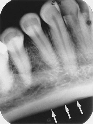
The term cortical is derived from the Latin word cortex and means “outer layer.” Cortical bone, also referred to as compact bone, is the dense outer layer of bone (Figure 27-1). Cortical bone resists the passage of the x-ray beam and appears radiopaque on a dental image. The inferior border of the mandible is composed of cortical bone and appears radiopaque (Figure 27-2).
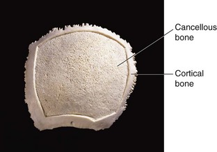
Cancellous Bone
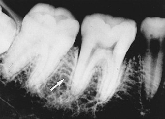
The term cancellous is also derived from Latin and means “arranged like a lattice.” Cancellous bone is the soft, spongy bone located between two layers of dense cortical bone (see Figure 27-1). Cancellous bone is composed of numerous bony trabeculae that form a latticelike network of intercommunicating spaces filled with bone marrow. The trabeculae, actual pieces of bone, resist the passage of the x-ray beam and appear radiopaque; in contrast, the marrow spaces permit the passage of the x-ray beam and appear radiolucent. The larger the trabeculations, the more radiolucent the area of cancellous bone appears. Cancellous bone appears predominantly radiolucent (Figure 27-3).
Prominences of Bone
Prominences of bone are composed of dense cortical bone and appear radiopaque on dental images. Five terms can be used to describe the bony prominences seen in maxillary and mandibular periapical images, as follows:
Process: A marked prominence or projection of bone; an example is the coronoid process of the mandible (Figure 27-4).
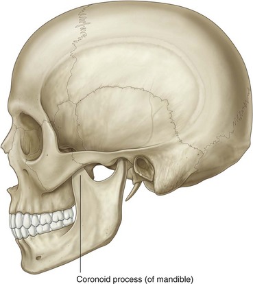
FIGURE 27-4 Coronoid process. (From Drake RL, et al: Gray’s atlas of anatomy, Philadelphia, 2008, Churchill Livingstone).
Ridge: A linear prominence or projection of bone; an example is the internal oblique ridge of the mandible (Figure 27-5).
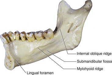
FIGURE 27-5 Internal oblique ridge, submandibular fossa, mylohyoid ridge, and lingual foramen. (From Liebgott B: The anatomical basis of dentistry, ed 3, St. Louis, 2011, Mosby).
Spine: A sharp, thornlike projection of bone; an example is the anterior nasal spine of the maxilla (Figure 27-6).
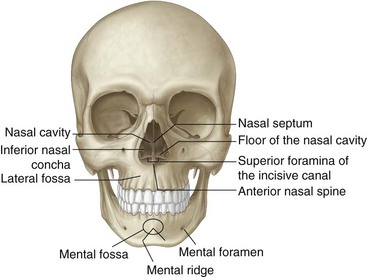
FIGURE 27-6 Anterior nasal spine, mental foramen, nasal septum, superior foramina of the incisive canal, lateral fossa, nasal cavity, the floor of the nasal cavity, inferior nasal concha, mental fossa, and mental ridge. (From Drake RL, et al: Gray’s atlas of anatomy, Philadelphia, 2008, Churchill Livingstone).
Tubercle: A small bump or nodule of bone; an example is the genial tubercles of the mandible (Figure 27-7).
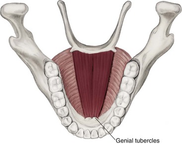
FIGURE 27-7 Genial tubercles. (From Fehrenbach MF, Herring SW: Illustrated anatomy of the head and neck, ed 3, St. Louis, 2007, Saunders).
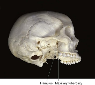
Tuberosity: A rounded prominence of bone; an example is the maxillary tuberosity (Figure 27-8).
Spaces and Depressions in Bone
Spaces and depressions in bone do not resist the passage of the x-ray beam and appear radiolucent on dental images. Four terms can be used to describe the spaces and depressions in bone viewed in maxillary and mandibular periapical images, as follows:
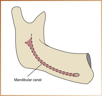
Canal: A tubelike passageway through bone that contains nerves and blood vessels; an example is the mandibular canal (Figure 27-9).
Foramen: An opening or hole in bone that permits the passage of nerves and blood vessels; an example is the mental foramen of the mandible (see Figure 27-6).
Fossa: A broad, shallow, scooped-out or depressed area of bone; an example is the submandibular fossa of the mandible (see Figure 27-5).
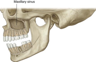
Sinus: A hollow space, cavity, or recess in bone; an example is the maxillary sinus (Figure 27-10).
Miscellaneous Terms
Two other general terms can be used to describe normal landmarks viewed on a dental image, as follows:
Septum: A bony wall or partition that divides two spaces or cavities. A septum may be present within the space of a fossa or sinus. A bony septum appears radiopaque, in contrast to a space or cavity, which appears radiolucent. An example is the nasal septum (see Figure 27-6).
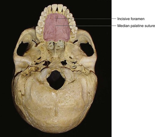
Suture: An immovable joint that represents a line of union between adjoining bones of the skull. Sutures are found only in the skull. On dental images, a suture appears as a thin radiolucent line. An example is the median palatine suture of the maxilla (Figure 27-11).
Normal Anatomic Landmarks
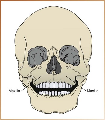
The upper jaw is composed of two paired bones, the maxillae (Figure 27-12). The paired maxillae meet at the midline of the face and are often referred to as a single bone, the maxilla. The maxilla has been described as the architectural cornerstone of the face. All the bones of the face, with the exception of the mandible, articulate with the maxilla. The maxilla forms the floor of the orbit of the eyes, the sides and floor of the nasal cavities, and the hard palate. The lower border of the maxilla supports maxillary teeth. This section reviews bony landmarks that frequently appear in maxillary periapical images.
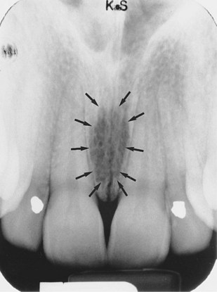
Incisive Foramen
Description: The incisive foramen (also known as the nasopalatine foramen) is an opening or hole in bone located at the midline of the anterior portion of the hard palate directly posterior to maxillary central incisors (see Figure 27-11). The nasopalatine nerve exits the maxilla through the incisive foramen.
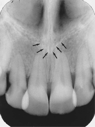
Appearance: On a maxillary periapical image, the incisive foramen appears as a small, ovoid or round radiolucent area located between the roots of the maxillary central incisors (Figure 27-13).
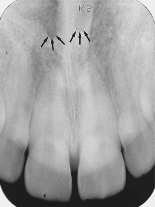
Superior Foramina of Incisive Canal
Description: The superior foramina of the incisive canal are two tiny openings or holes in bone that are located on the floor of the nasal cavity (foramina is the plural of foramen) (see Figure 27-6). The superior foramina are the openings of two small canals that extend downward and medially from the floor of the nasal cavity. These two small canals join together to form the incisive canal and share a common exit, the incisive foramen. The nasopalatine nerve enters the maxilla through the superior foramina, travels through the incisive canal, and exits at the incisive foramen.
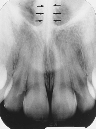
Appearance: On a maxillary periapical image, the superior foramina appear as two small, round radiolucencies located superior to the apices of the maxillary central incisors (Figure 27-14).
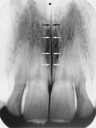
Median Palatal Suture
Description: The median palatal suture is the immovable joint between the two palatine processes of the maxilla. (The palatine processes of the maxilla form the major portion of the hard palate.) The median palatal suture extends from the alveolar bone between the maxillary central incisors to the posterior hard palate (see Figure 27-11).
Appearance: On a maxillary periapical image, the median palatal suture appears as a thin radiolucent line between maxillary central incisors (Figure 27-15). The median palatal suture is bounded on both sides by dense cortical bone that appears radiopaque. As the median palatal suture fuses with age, it may become less distinct on a dental image.
Lateral Fossa
Description: The lateral fossa (also known as the canine fossa) is a smooth, depressed area of the maxilla located just inferior and medial to the infraorbital foramen between maxillary canine and lateral incisors (see Figure 27-6).
Appearance: On a maxillary periapical image, the lateral fossa appears as a radiolucent area between maxillary canine and lateral incisors (Figure 27-16). In some periapical images, the lateral fossa may appear as a distinct radiolucency; in others, it may appear to be absent. The appearance of the lateral fossa varies depending on the anatomy of the individual.
Nasal Cavity
Description: The nasal cavity (also known as the nasal fossa) is a pear-shaped compartment of bone located superior to the maxilla (see Figure 27-6). The inferior portion, or floor, of the nasal cavity is formed by the palatal processes of the maxilla and the horizontal portions of palatine bones. The lateral walls of the nasal cavity are formed by the ethmoid bone and the maxillae. The nasal cavity is divided by a bony partition, or wall, called the nasal septum.
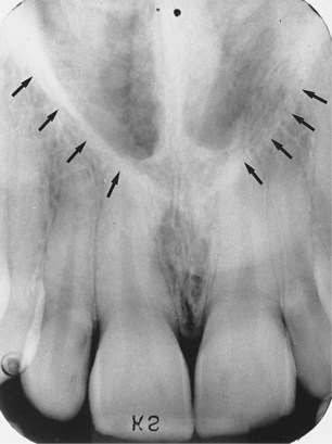
Appearance: On a maxillary periapical image, the nasal cavity appears as a large, radiolucent area superior to maxillary incisors (Figure 27-17).
Nasal Septum
Description: The nasal septum is a vertical bony wall or partition that divides the nasal cavity into the right and left nasal fossae (fossae is the plural of fossa) (see Figure 27-6). The nasal septum is formed by two bones—the vomer and a portion of the ethmoid bone—and cartilage.
Appearance: On a maxillary periapical image, the nasal septum appears as a vertical radiopaque partition that divides the nasal cavity (Figure 27-18). The nasal septum may be superimposed over the median palatal suture.
Floor of Nasal Cavity
Description: The floor of the nasal cavity is a bony wall formed by the palatal processes of the maxilla and the horizontal portions of palatine bones (see Figure 27-6). The floor is composed of dense cortical bone and defines the inferior border of the nasal cavity.
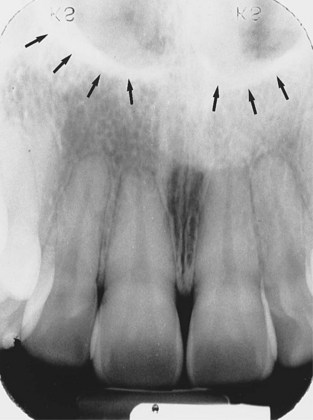
Appearance: On a maxillary periapical image, the floor of the nasal cavity appears as a dense radiopaque band of bone superior to maxillary incisors (Figure 27-19).
Anterior Nasal Spine
Description: The anterior nasal spine is a sharp projection of the maxilla located at the anterior and inferior portion of the nasal cavity (see Figure 27-6).
Appearance: On a maxillary periapical image, the anterior nasal spine appears as a V-shaped radiopaque area located at the intersection of the floor of the nasal cavity and the nasal septum (Figure 27-20).
Inferior Nasal Conchae
Description: Inferior nasal conchae are wafer-thin, curved plates of bone that extend from the lateral walls of the nasal cavity (see Figure 27-6). Inferior nasal conchae are seen in the lower lateral portions of the nasal cavity. The term concha is derived from Latin and means “shell shaped” or “scroll shaped.”
Appearance: On a maxillary periapical image, inferior nasal conchae appear as a diffuse radiopaque mass or projection within the nasal cavity (Figure 27-21).
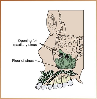
Maxillary Sinus
Description: Maxillary sinuses are paired cavities or compartments of bone located within the maxilla (see Figure 27-10). Maxillary sinuses are located superior to maxillary premolar and molar teeth. Rarely does the maxillary sinus extend anteriorly beyond the canines. At birth, the maxillary sinus is the size of a small pea. With growth, the maxillary sinus expands and eventually occupies a large portion of the maxilla. The maxillary sinus may extend to include interdental bone, molar furcation areas, or the maxillary tuberosity region.
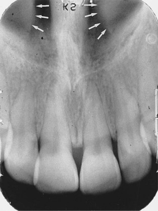
Appearance: On a maxillary periapical image, the maxillary sinus appears as a radiolucent area located superior to the apices of maxillary premolars and molars (Figures 27-22, and 27-23). The floor of the maxillary sinus is composed of dense cortical bone and appears as a radiopaque line.
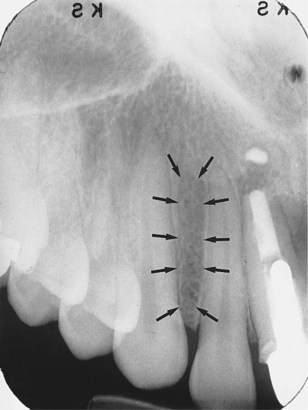
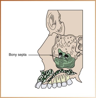
Septa within Maxillary Sinus
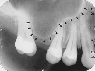
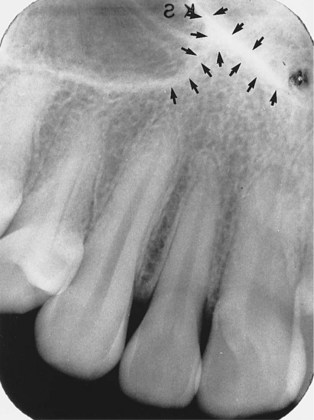
Description: Bony septa (septa is the plural of septum) may be seen within the maxillary sinus. Septa are bony walls or partitions that appear to divide the maxillary sinus into compartments (Figure 27-24).
Appearance: On a maxillary periapical image, the septa appear as radiopaque lines within the maxillary sinus (Figure 27-25). In some periapical images, the septa appear as distinct radiopaque lines; in others, no septa are seen. The presence and number of bony septa within a maxillary sinus vary depending on the anatomy of the individual.
Nutrient Canals within Maxillary Sinus
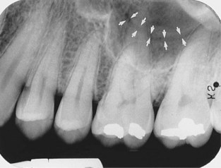
Description: Nutrient canals may be seen within maxillary sinuses. Nutrient canals are tiny, tubelike passageways through bone, which contain blood vessels and nerves that supply maxillary teeth and interdental areas.
Appearance: On a maxillary periapical image, a nutrient canal appears as a narrow radiolucent band bounded by two thin radiopaque lines (Figure 27-26). The radiopaque lines represent the cortical bone that makes up the walls of the canal.
Inverted Y
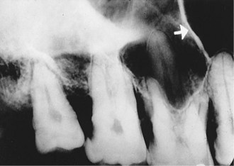
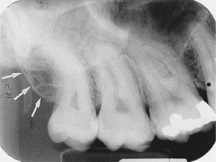
Description: The term inverted Y refers to the intersection of the maxillary sinus and the nasal cavity as viewed on a dental image.
Appearance: On a maxillary periapical image, the inverted Y appears as a radiopaque upside-down Y formed by the intersection of the lateral wall of the nasal fossa and the anterior border of the maxillary sinus (Figure 27-27). The lateral wall of the nasal cavity and the anterior border of the maxillary sinus are both composed of dense cortical bone and appear as a radiopaque line or band. The inverted Y is located superior to the maxillary canine.
Maxillary Tuberosity
Description: The maxillary tuberosity is a rounded prominence of bone that extends posterior to the third molar region (see Figure 27-8). Blood vessels and nerves enter the maxilla in this region and supply posterior teeth.
Appearance: On a maxillary periapical image, the maxillary tuberosity appears as a radiopaque bulge distal to the third molar region (Figure 27-28).
Hamulus
Description: The hamulus (also known as the hamular process) is a small, hooklike projection of bone extending from the medial pterygoid plate of the sphenoid bone (see Figure 27-8). The hamulus is located posterior to the maxillary tuberosity region.
Appearance: On a maxillary periapical image, the hamulus appears as a radiopaque hooklike projection posterior to the maxillary tuberosity area (Figure 27-29). The image appearance of the hamulus varies in length, shape, and density.
Zygomatic Process of Maxilla
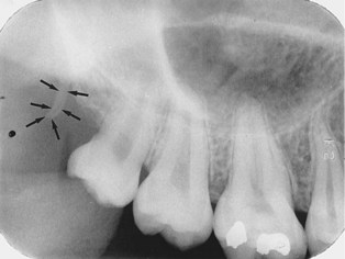
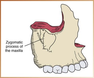
Description: The zygomatic process of the maxilla is a bony projection of the maxilla that articulates with the zygoma, or malar bone (Figure 27-30). The zygomatic process of the maxilla is composed of dense cortical bone.
Appearance: On a maxillary periapical image, the zygomatic process of the maxilla appears as a J-shaped or U-shaped radiopacity located superior to the maxillary first molar region (Figure 27-31).
Zygoma
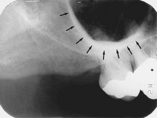
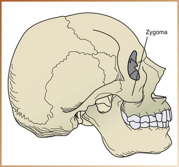
Description: The zygoma, or “cheekbone” (also referred to as the malar bone or zygomatic bone) articulates with the zygomatic process of the maxilla (Figure 27-32). The zygoma is composed of dense cortical bone.
Appearance: On a maxillary periapical image, the zygoma appears as a diffuse radiopaque band extending posteriorly from the zygomatic process of the maxilla (Figure 27-33).
Bony Landmarks of the Mandible
The mandible, the largest and strongest bone of the face, can be divided into three main parts: the ramus, the body, and the alveolar process (Figure 27-34).
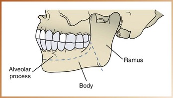
• Ramus. The ramus is the vertical portion of the mandible that is found posterior to the third molar. The mandible has two rami (rami is the plural of ramus), one on each side.
• Body of mandible. The body of the mandible is the horizontal, U-shaped portion that extends from ramus to ramus.
• Alveolar process. The alveolar process is the portion of the mandible that encases and supports teeth.
This section reviews the bony landmarks that frequently appear in mandibular periapical images.
Genial Tubercles
Description: Genial tubercles are tiny bumps of bone that serve as attachment sites for the genioglossus and geniohyoid muscles (see Figure 27-7). Genial tubercles are located on the lingual aspect of the mandible.
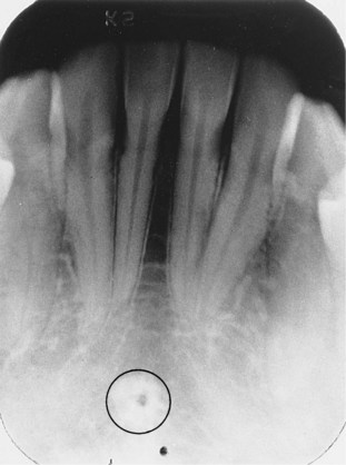
Appearance: On a mandibular periapical image, genial tubercles appear as a ring-shaped radiopacity inferior to the apices of the mandibular incisors (Figure 27-35).
Lingual Foramen
Description: The lingual foramen is a tiny opening or hole in bone located on the internal surface of the mandible (see Figure 27-5). The lingual foramen is located near the midline and is surrounded by genial tubercles.
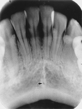
Appearance: On a mandibular periapical image, the lingual foramen appears as a small, radiolucent dot located inferior to the apices of mandibular incisors (Figure 27-36). The lingual foramen is surrounded by genial tubercles, which appear as a radiopaque ring.
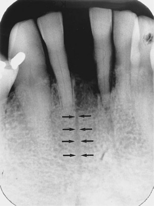
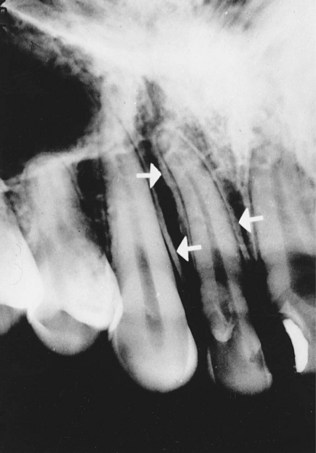
Nutrient Canals
Description: As described earlier, nutrient canals are tubelike passageways through bone that contain nerves and blood vessels that supply teeth. Interdental nutrient canals are most often seen in the anterior mandible, a region that typically has thin bone.
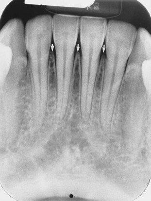
Appearance: On a mandibular periapical image, nutrient canals appear as vertical radiolucent lines (Figure 27-37). On a dental image, nutrient canals are readily seen in areas of thin bone. In the edentulous mandible, nutrient canals may be more prominent.
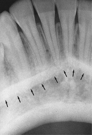
Mental Ridge
Description: The mental ridge is a linear prominence of cortical bone located on the external surface of the anterior portion of the mandible (see Figure 27-6). The mental ridge extends from the premolar region to the midline and slopes slightly upward.
Appearance: On a mandibular periapical image, the mental ridge appears as a thick radiopaque band that extends from the premolar region to the incisor region (Figure 27-38). On a dental image, the mental ridge often appears superimposed over mandibular anterior teeth.
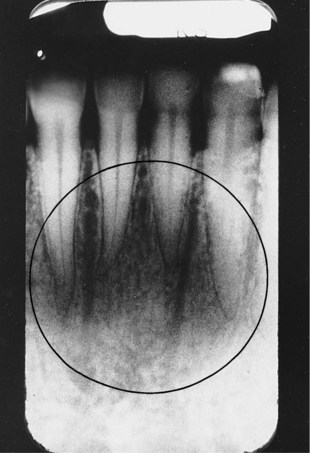
Mental Fossa
Description: The mental fossa is a scooped-out, depressed area of bone located on the external surface of the anterior mandible (see Figure 27-6). The mental fossa is located above the mental ridge in the mandibular incisor region.
Appearance: On a mandibular periapical image, the mental fossa appears as a radiolucent area above the mental ridge (Figure 27-39). On a dental image, the appearance of the mental fossa varies and is determined by the thickness of the bone in the anterior region of the mandible.
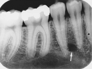
Mental Foramen
Description: The mental foramen is an opening or hole in bone located on the external surface of the mandible in the region of mandibular premolars (see Figure 27-6). Blood vessels and nerves that supply the lower lip exit through the mental foramen.
Appearance: On a mandibular periapical image, the mental foramen appears as a small, ovoid or round radiolucent area located in the apical region of mandibular premolars (Figure 27-40). The mental foramen may be misdiagnosed as a periapical lesion (periapical cyst, granuloma, or abscess) because of its apical location.
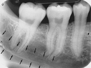
Mylohyoid Ridge
Description: The mylohyoid ridge is a linear prominence of bone located on the internal surface of the mandible (see Figure 27-5). The mylohyoid ridge extends from the molar region downward and forward toward the lower border of the mandibular symphysis. The mylohyoid ridge serves as an attachment site for a muscle of the same name.
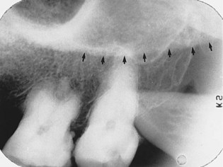
Appearance: On a mandibular periapical image, the mylohyoid ridge appears as a dense radiopaque band that extends downward and forward from the molar region (Figure 27-41). The mylohyoid ridge usually appears most prominently in the molar region and may be superimposed over the roots of mandibular teeth. The mylohyoid ridge may appear to be continuous with the internal oblique ridge.
Mandibular Canal
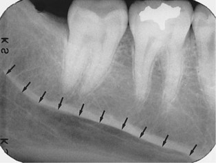
Description: The mandibular canal is a tubelike passageway through bone that travels the length of the mandible. The mandibular canal extends from the mandibular foramen to the mental foramen and houses the inferior alveolar nerve and blood vessels.
Appearance: On a mandibular periapical image, the mandibular canal appears as a radiolucent band (Figure 27-42). The mandibular canal is outlined by two thin radiopaque lines that represent the cortical walls of the canal. The mandibular canal appears below or superimposed over the apices of mandibular molar teeth.
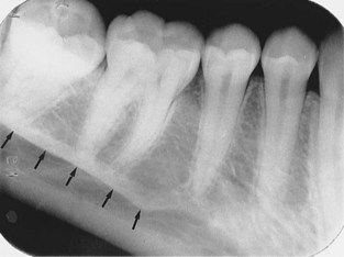
Internal Oblique Ridge
Description: The internal oblique ridge (also known as the internal oblique line) is a linear prominence of bone located on the internal surface of the mandible that extends downward and forward from the ramus (see Figure 27-5). The internal oblique ridge may end in the region of the mandibular third molar, or it may continue on as the mylohyoid ridge.
Appearance: On a mandibular periapical image, the internal oblique ridge appears as a radiopaque band that extends downward and forward from the ramus (Figure 27-43). Depending on the exposure technique used (bisecting versus paralleling), the internal and external oblique ridges may be superimposed on one another. When the ridges appear separate, the superior radiopaque band is the external oblique ridge, and the inferior radiopaque band is the internal oblique ridge.
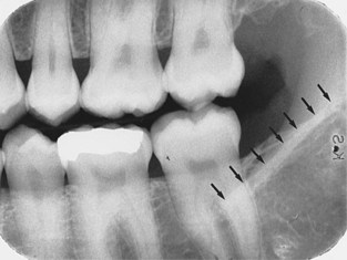
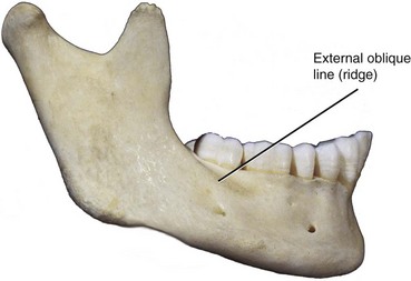
External Oblique Ridge
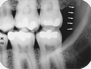
Description: The external oblique ridge (also known as the external oblique line) is a linear prominence of bone located on the external surface of the body of the mandible (see Figure 27-44). The anterior border of the ramus ends in the external oblique ridge.
Appearance: On a mandibular periapical image, the external oblique ridge appears as a radiopaque band extending downward and forward from the anterior border of the ramus of the mandible (Figure 27-45). The external oblique ridge typically ends in the mandibular third molar region.
Submandibular Fossa
Description: The submandibular fossa (also known as the mandibular fossa or submaxillary fossa) is a scooped-out, depressed area of bone located on the internal surface of the mandible inferior to the mylohyoid ridge (see Figure 27-5). The submandibular salivary gland is found in the submandibular fossa.
Appearance: On a mandibular periapical image, the submandibular fossa appears as a radiolucent area in the molar region below the mylohyoid ridge (Figure 27-46). Few bony trabeculae are usually seen in the region of the submandibular fossa. On some periapical images, the submandibular fossa may appear as a distinct radiolucency; in others, it may be slightly more radiolucent than the adjacent bone.
Coronoid Process
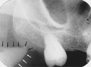
Description: The coronoid process is a marked prominence of bone on the anterior ramus of the mandible (see Figure 27-4). The coronoid process serves as an attachment site for one of the muscles of mastication.
Appearance: The coronoid process is not seen on a mandibular periapical image but does appear on a maxillary molar periapical image. The coronoid process appears as a triangular radiopacity superimposed over, or inferior to, the maxillary tuberosity region (Figure 27-47).
Normal Tooth Anatomy
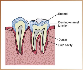
Tooth structures that can be viewed on dental images include the following: enamel, dentin, the dentino-enamel junction, and the pulp cavity (Figure 27-48).
Enamel
Enamel is the densest structure found in the human body. Enamel is the outermost radiopaque layer of the crown of a tooth (Figure 27-49).

Dentin
Dentin is found beneath the enamel layer of a tooth and surrounds the pulp cavity (see Figure 27-49). Dentin appears radiopaque and makes up the majority of the tooth structure. Dentin is not as radiopaque as enamel.
Dentino-Enamel Junction
The dentino-enamel junction (DEJ) is the junction between the dentin and the enamel of a tooth. The DEJ appears as a line where the enamel (very radiopaque) meets the dentin (less radiopaque) (see Figure 27-49).
Pulp Cavity
The pulp cavity consists of a pulp chamber and pulp canals. It contains blood vessels, nerves, and lymphatics and appears relatively radiolucent on a dental image (Figure 27-50). When viewed on a dental image, the pulp cavity is generally larger in children than in adults because it decreases in size with age due to the formation of secondary dentin. The size and shape of a pulp cavity vary with each tooth.
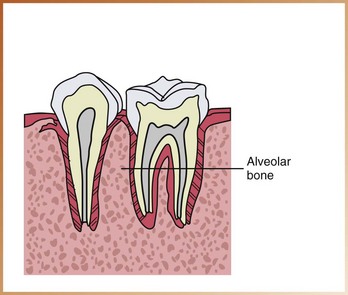
Supporting Structures
The alveolar process, or alveolar bone, serves as the supporting structure for teeth. The alveolar bone is the bone of the maxilla and the mandible that supports and encases the roots of teeth (Figure 27-51). Alveolar bone is composed of dense cortical bone and cancellous bone.
Anatomy of Alveolar Bone
The anatomic landmarks of the alveolar process include the lamina dura, the alveolar crest, and the periodontal ligament space (Figure 27-52).
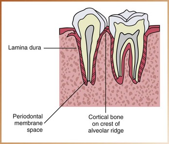
Lamina Dura
Description: The lamina dura is the wall of the tooth socket that surrounds the root of a tooth. The lamina dura is made up of dense cortical bone.
Appearance: On a dental image, the lamina dura appears as a dense radiopaque line that surrounds the root of a tooth (Figure 27-53).
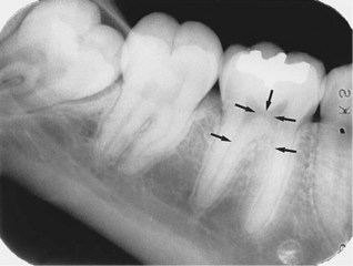
Alveolar Crest
Description: The alveolar crest is the most coronal portion of alveolar bone found between teeth. The alveolar crest is made up of dense cortical bone and is continuous with the lamina dura.
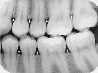
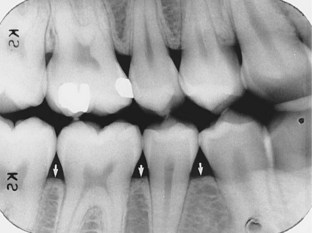
Appearance: On a dental image, the alveolar crest appears radiopaque and is typically located 1.5 to 2.0 mm below the junction of the crown and the root surfaces (the cemento-enamel junction) (Figure 27-54).
Periodontal Ligament Space
Description: The periodontal ligament space (PDL space) is the space between the root of the tooth and the lamina dura. The PDL space contains connective tissue fibers, blood vessels, and lymphatics.
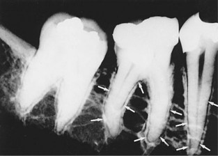
Appearance: On a dental image, the PDL space appears as a thin radiolucent line around the root of a tooth. In the healthy periodontium, the PDL space appears as a continuous radiolucent line of uniform thickness (Figure 27-55).
Shape and Density of Alveolar Bone
Alveolar bone located between the roots of teeth varies in shape and density.
Anterior Region: Normal alveolar crest located in the anterior region appears pointed and sharp between teeth (Figure 27-56). The alveolar crest appears as a dense radiopaque line in the anterior region.
Posterior Region: Normal alveolar crest located in the posterior region appears flat and smooth between teeth (Figure 27-57). The alveolar crest located in the posterior region tends to appear less dense and less radiopaque than the alveolar crest seen in the anterior region.
Summary
• The dental radiographer must have a thorough knowledge of the anatomy of the maxilla and the mandible; each normal anatomic landmark seen on a periapical image corresponds to that seen on the human skull. Knowledge of the anatomy of the maxilla and the mandible as viewed on an image of the human skull enables the dental radiographer to identify the normal anatomy that is found on a periapical image.
• Recognition of normal anatomic landmarks enables the dental radiographer to distinguish between maxillary and mandibular periapical and accurately mount dental images.
• Recognition of normal anatomic landmarks is also necessary for the accurate interpretation of dental images. Knowledge of the normal anatomy seen on periapical images is essential before the dental radiographer can begin to recognize abnormalities (e.g., diseases, lesions).
• Each normal anatomic landmark as viewed on a periapical image is described in this chapter.
Frommer, HH, Savage-Stabulas, JJ, Film mounting and radiographic anatomy. Radiology for the dental professional, ed 9, St. Louis, Mosby, 2011.
Haring, JI, Lind, LJ. Normal anatomy (periapical films). In: Radiographic interpretation for the dental hygienist. Philadelphia: Saunders; 1993.
Miles, DA, Van Dis, ML, Jensen, CW, Ferretti, A, Normal anatomy and film mounting. Radiographic imaging for dental auxiliaries, ed 3, St. Louis, Saunders, 2009.
White, SC, Pharaoh, MJ, Normal radiographic anatomy. Oral radiology: principles of interpretation, ed 6, St. Louis, Mosby, 2009.
Matching
Identification
For questions 9 to 16, refer to Figures 27-58 through 27-65. Identify the normal anatomic landmarks indicated by arrows (or circle) as required.
9. Identify the normal anatomic landmark shown in Figure 27-58.
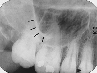
FIGURE 27-58
10. Identify the normal anatomic landmark shown in Figure 27-59.
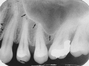
FIGURE 27-59
11. Identify the normal anatomic landmark shown in Figure 27-60.
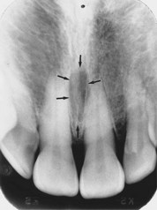
FIGURE 27-60
12. Identify the normal anatomic landmark shown in Figure 27-61.
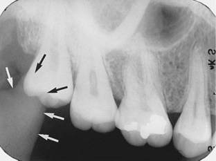
FIGURE 27-61
13. Identify the normal anatomic landmark shown in Figure 27-62.
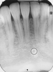
FIGURE 27-62
14. Identify the normal anatomic landmark shown in Figure 27-63.
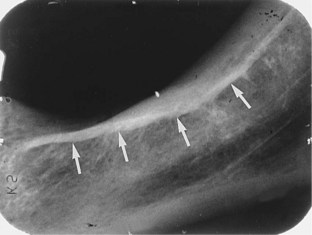
FIGURE 27-63
15. Identify the normal anatomic landmark shown in Figure 27-64.

FIGURE 27-64
16. Identify the normal anatomic landmark shown in Figure 27-65.
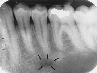
FIGURE 27-65