Chapter 20 Computed Tomography
Physics
Computed tomography (CT) is a well-established diagnostic imaging modality that has been in clinical use in medicine for several decades but only recently has become commonly used in veterinary medicine. The essential concept of a CT scanner is that an x-ray–generating tube is positioned across from a row of digital x-ray detectors in a circular gantry. The tube and detectors spin around the outside of a horse, creating a continuous radiographic image through 360 degrees. The detectors are linked to a computer system that manipulates the imaging data by a process called back projection, thereby generating cross-sectional images based on the subject density.1
Equipment
CT hardware, like most imaging technology, has undergone extensive revision since its inception. One of the most important advances in CT hardware was the advent of the slip ring, allowing for helical scanning. With helical scanning, the x-ray tube and detectors continuously spin around the horse while it translates or moves through the center of the gantry. The resultant path of the x-ray tube relative to the horse is helical, giving the technique its name. Another, equally important, major advance is the advent of multislice technology. Multislice CT is a modification of the aforementioned basic configuration whereby multiple detector rows are positioned opposite the x-ray generator. The x-ray generator exposes the subject, and the transmitted x-rays are detected by several rows of detectors on the opposite side of the gantry. Since the first appearance of a dual-slice CT scanner, this technology has burgeoned, and now up to 256-slice scanners are available. The number of detector rows determines the number of images that can be acquired per rotation of the gantry components, meaning that a four-slice scanner can acquire four images per rotation.
In order for horses to be imaged, careful consideration must be given both to the design of the CT table and to the size of the CT gantry opening. The CT table must not only support the weight of the horse but also move with speed and great precision. For a single-slice helical scanner acquiring 1-mm–thick images, the horse must move 1 mm per rotation of the gantry, which generally occurs in about 0.8 seconds. In order to accomplish this, equine CT tables have been custom-designed to work with those manufactured for scanning people. More recently, commercially available equine CT tables have come onto the market (Figure 20-1). An alternative style of CT scanner has recently resurfaced as an option for horses. This type of CT gantry can be equipped with multislice capabilities and is portable. The gantry translates around the outside of the horse with the requisite precision and speed. CT scanners have been built for human applications and as such typically have a circular gantry opening of around 70 cm, which determines the maximum size of the patient or area to be scanned. Currently scanners with 30- to 35-cm openings are commercially available and are appropriate for equine extremity work. There is a movement toward larger gantry sizes that will likely result in machines with >80-cm openings becoming available in the near future, which should increase the clinical utility of equine CT to include larger anatomical regions.
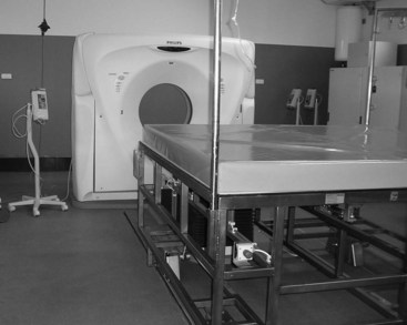
Image Display and Processing
Image Display
CT images map tissue density in the subject. Each pixel in the two-dimensional CT image actually represents a volume of tissue or volume element (voxel) defined by the pixel size in two dimensions and slice thickness in the third dimension. Typical slice thickness ranges from 1 to 10 mm, and now with multislice scanners, images less than 1 mm thick can be obtained. For each voxel, a value is recorded in Hounsfield units (HU) or CT units. This numerical value represents the density of the tissue within the voxel relative to water, which is arbitrarily set to equal zero. Density values of common tissues are listed in Box 20-1. Lesions can be described as hypodense or hyperdense.
BOX 20-1 Density Values of Different Tissues
| Tissue | Density (Hounsfield Units [HU]) |
|---|---|
| Gas | −1000 |
| Fat | −120 |
| Water | 0 |
| Muscle | 40 |
| Equine DDFT | 90-120 |
| Medullary bone | 400-600 |
| Cortical bone | 1500 |
DDFT, Deep digital flexor tendon.
The viewer, using routinely available image review software, can reversibly manipulate the displayed grayscale value of the tissues. Using a wide “window width” is appropriate for the evaluation of tissues with a wide density range such as bone (approximately 400 to 1500 HU). Viewing with a narrow window produces higher image contrast and is appropriate for the evaluation of tissues with a narrow density range such as soft tissue (approximately 40 to 120 HU). “Level” is to the midpoint of the grey shades that are displayed. Changing the level increases or decreases the brightness of the image. In order to perform a complete and thorough evaluation of CT images, the viewer should actively manipulate both window width and level to view all tissues (Figure 20-2).
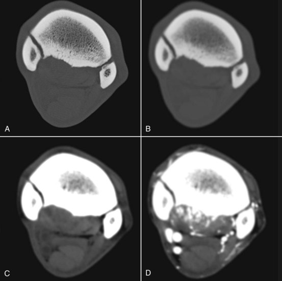
Figure 20-2 Transverse computed tomography images all acquired at the same location in the proximal metacarpal region, but processed and displayed differently. Medial is to the left. A has a wide window width and has been processed with an edge-enhancing algorithm to enable accurate assessment of bone. B has the same window, but a smoothing algorithm has been applied for evaluation of the soft tissues. C is a soft tissue algorithm with a narrow window width. D is the same location after the regional administration of contrast medium. This horse has suspensory ligament injury that is moderately contrast enhancing with associated entheous and endosteal new bone at its origin. Note the irregular contour of the palmar cortex of the third metacarpal bone, seen best in A and B, and the periarticular osteophyte bridging the articulation between the second and third metacarpal bones. In C, note the hypodense areas in the suspensory ligament corresponding to areas that show contrast enhancement in D. The superficial and deep digital flexor tendons and the accessory ligament of the deep digital flexor tendon have uniform density.
Image Processing
Image processing refers to mathematical manipulation of the images and is most often performed in the background at the time of acquisition. Processing is used to improve the appearance of an image or help the viewer to better evaluate one type of structure such as soft tissue versus bone (see Figure 20-2).2
Image Reconstruction
Image reformatting and reconstruction are routinely used to manipulate the imaging data to appear differently. Image reformatting is the simplest form of reconstruction and is the process by which the viewer can “reslice” the imaging information into a different orientation (Figure 20-3). The resultant images are two-dimensional cross-sections of anatomy. The quality of the reconstructed images is highly dependent on the original slice thickness and the slice interval. Thinner slices that overlap result in better images than thicker slices or slices that do not overlap. Helical scanners are capable of producing overlapping slices, and multislice scanners can acquire images that are less than 1 mm in thickness.

Figure 20-3 Tranverse computed tomography images on the right (medial to the left) correspond to the levels shown by the white lines on the sagittal plane image on the left, which is reformatted from the original series. A medial lobe lesion is present in the deep digital flexor tendon (DDFT) in the pastern (arrow), and biaxial dorsal lesions are present in the DDFT in the heel region, characterized by hypodense foci (arrows) and navicular bursa effusion laterally (*).
Three-dimensional (3D) reconstructions use the voxel density value (HU) to create models that represent anatomy in a completely different format. Two commonly used types of 3D reconstructions are termed surface rendering and volume rendering. In a surface-rendered image, the viewer selects a minimum density threshold so that only tissue of higher density than the threshold is displayed. This technique can be useful to create a topographical impression of a fractured bone. Volume rendering uses the same principle, but a color scheme is used to depict tissues within a specific density range. The resultant image depicts the color-coded structure from whichever external viewpoint the viewer chooses. Figure 20-4 shows an intraarterial CT angiogram, viewed from the palmaromedial aspect, in which the operator has progressively increased the minimum threshold so that all tissues of lower density are removed. The final image has a threshold of about 550 HU, and only the surface of the bone and the contrast medium within the major vessels are visible.
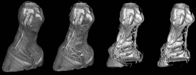
Figure 20-4 Three-dimensional volume-rendered images of a computed tomography angiogram. The operator has progressively increased the threshold from left to right. On the left, most of the soft tissues including the hoof capsule can be identified. Extending to the right, the soft tissues disappear first, followed by the hoof capsule and then the small-caliber laminar blood vessels. On the image on the right, only the larger blood vessels containing contrast media and bone surface are visible. This horse has erosion of the flexor cortex of the navicular bone.
Contrast Media
Contrast media are available for all diagnostic imaging modalities and are used to better identify or more thoroughly characterize either normal or abnormal structures. Routine radiographic contrast media (barium or iodine based) can be used to augment the clinical utility of CT. Most commonly, iodine-based injectable contrast media are given by the intravascular route to identify regions of increased blood flow or vascular permeability, as expected with injured or inflamed soft tissues. Regional intraarterial administration with concurrent CT scanning has been described to aid in the identification of soft tissue lesions of the foot.3,4 This technique is also useful for regions higher in the limb—for example, to evaluate the suspensory ligament of both forelimbs (see Figure 20-2) and hindlimbs and the structures within the carpal canal. In the early phases of tendon and ligament injury, contrast medium is present in increased quantity because of extravasation from abnormally permeable blood vessels. As a lesion heals, neovascularization develops; contrast medium is seen within small-caliber blood vessels.5 Alternatively, nonionic iodine-based contrast media can be injected into synovial spaces to surround and improve margin visibility of structures in or around joints, sheaths, and bursae. This allows for the evaluation of intraarticular ligaments (stifle, carpus) or the identification of adhesions (navicular bursa) or cartilage lesions. The systemic use of contrast medium in horses is impractical because of the large dose required and time-consuming administration.
Clinical Applications
Fracture Assessment
CT’s greatest strength is the detailed evaluation of osseous structures. The elimination of superimposition allows the viewer to detect small changes in bone density caused by osteolysis or proliferation that would go unnoticed on routine radiographs. This also applies to the detection of small fragments or comminuted fracture lines. These characteristics make CT an ideal choice to accurately characterize fractures, in order to establish prognosis or for preoperative planning. CT is particularly useful in evaluating fractures when they occur in complicated anatomical regions such as the carpus or tarsus (Figure 20-5). CT intraarterial angiography of the extremity can be performed to identify concurrent soft tissue and blood vessel trauma.
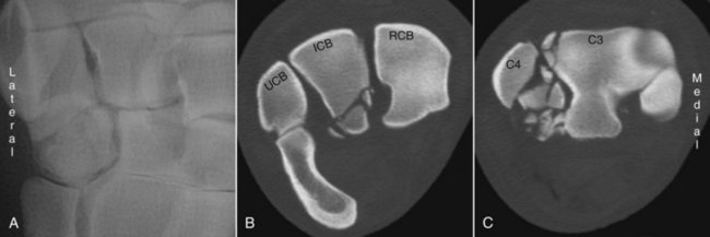
Figure 20-5 Three images from a horse that sustained carpal fractures. A is a dorsal 15-degree lateral-palmaromedial oblique radiographic image cropped to show fractures with mild displacement in the fourth carpal bone. B is a transverse computed tomography image at the level of the proximal row of carpal bones showing palmar, comminuted fractures of the intermediate carpal bone (ICB). C is obtained through the distal row of carpal bones. Marked fragmentation of the fourth carpal bone (C4) and a fracture of the lateral and dorsal aspects of the third carpal bone (C3) are present.
Lameness Diagnosis
The goal of diagnostic imaging is to accurately identify and thoroughly describe pathology. All diagnostic imaging techniques should be considered in the light of these goals. In some horses, it is difficult to identify lesions and to thoroughly describe underlying pathology using radiography and ultrasonography, the more routinely available imaging techniques. Advanced imaging should be used when either one of these goals is not met. In lameness diagnosis, advanced diagnostic imaging techniques will usually augment a clinical workup by providing additional or different information. The clinician must carefully evaluate each horse, weigh the cost-benefit ratio, and decide if additional diagnostic techniques are necessary to solve the clinical problem. Although CT scanning is rapid, limitations exist. CT should be used once the source of pain causing lameness is established, because it is largely impractical to “screen” numerous anatomical regions. Furthermore, general anesthesia, with its associated risks, is necessary in most horses to obtain high-quality diagnostic images.
At the Veterinary Medical Teaching Hospital of the University of California, Davis, the most common indication for using CT is the evaluation of lameness caused by foot pain. The addition of regional contrast medium improves the ability of CT to detect some of the commonly reported soft tissue injuries that occur deep within the hoof capsule. Lesions of the deep digital flexor tendon (DDFT) (Figure 20-6), and collateral ligaments of the distal interphalangeal joint, navicular bursa, collateral sesamoidean ligaments, and distal sesamoidean impar ligament are identified with similar frequency as those identified using magnetic resonance imaging (MRI).6,7 Only a few equine studies exist that directly compare CT with MRI in horses with foot pain.8,9 Recent studies show that contrast-enhanced CT compares favorably with MRI and pathology for the identification of DDFT lesions within the hoof capsule.10,11
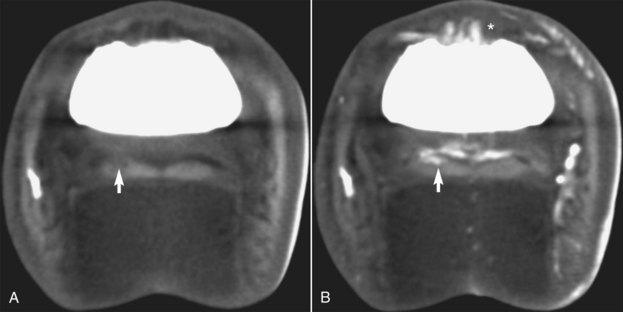
Figure 20-6 Transverse computed tomography (CT) images obtained at the level of the middle phalanx. A is a precontrast CT image, and B is an image obtained during an intraarterial infusion of contrast medium. A lesion (arrows) is present in one lobe of the deep digital flexor tendon. It is heterogeneous and hypodense on precontrast images (arrow) but has new vessel formation resulting in contrast enhancement of the lesion after contrast medium has been administered (arrow). There is also irregular enhancement of the synovium of the dorsal aspect of the distal interphalangeal joint (*).
CT is useful to identify conditions of bones and soft tissues, and its use is limited only by the physical configuration of the gantry and the size of horses. Most 70-cm gantry scanners are able to image up to the level of the distal diaphysis of the radius and tibia. CT is invaluable when routine diagnostic techniques are unable, because of inherent limitations of the technique, to thoroughly investigate an anatomical region. Valuable clinical information is gained from CT evaluation of subchondral bone, particularly the fetlock joint (Figure 20-7), the carpus and tarsus, and the origin of the suspensory ligament in both the forelimbs and hindlimbs (see Figure 20-2) and for evaluation of intracapsular soft tissue injury in the stifle. Contrast medium given through an intravascular route provides additional information about the underlying physiology of soft tissue structures. Tendon and ligament lesions appear hypodense, heterogeneous, and enlarged on plain CT, similar to other imaging modalities. After the administration of contrast material, soft tissue lesions typically enhance and appear hyperintense, thus helping the viewer to identify and characterize the abnormalities. CT is useful in regions where ultrasonographic evaluation is restricted by regional anatomy, such as the foot, carpal canal, or distal sesamoidean ligament attachments. Contrast medium administered into a synovial structure outlines the structures in contact with the synovial fluid. This has been particularly useful in the evaluation of intraarticular soft tissue structures such as the cruciate and meniscal ligaments and the menisci of the equine stifle.12 Arthrography also permits an indirect evaluation of the overlying articular cartilage. This can be effective in locations inaccessible to direct observation using arthroscopy.
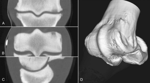
Figure 20-7 Computed tomography images from a horse with subchondral bone injury of the distal aspect of the third metacarpal bone and periarticular osteophyte formation of the metacarpophalangeal joint. A is in a dorsal plane, B is in a transverse plane, and C is in a sagittal plane. D is a three-dimensional reconstruction with the opacity of the proximal phalanx reduced to show the articular surface of the distal aspect of the third metacarpal bone (McIII). In A, B, and C, note the hypodense areas in the subchondral bone of the dorsal aspect of the medial condyle of the McIII.
Laminitis Evaluation
The role of CT in evaluating horses with laminitis has yet to be defined. The addition of intravascular contrast medium provides an unobstructed view of regional vasculature (see Figure 20-4). High bone detail provides an excellent way to evaluate the distal phalanx and its response to laminitis. Furthermore, quantitative techniques using dynamic contrast-enhanced CT for the measurement of blood flow have been developed and may play a role in evaluating horses with laminitis and in research studies.13
Interventional Computed Tomography
CT is able to accurately image metallic structures and can therefore be used to guide procedures. Most commonly this technique is used to guide the needle placement for tissue or fluid sampling or in therapeutics, such as for the delivery of medication. Intralesional medication can be accurately delivered to those structures inaccessible to ultrasonographic guidance such as the DDFT within the hoof capsule. CT is used to guide surgical procedures such as debridement of the distal phalanx, partial hoof wall resection, and subcapsular mass removal from the hoof.
Advantages and Disadvantages
Advantages
CT scanning is more rapid than high- and low-field MRI. This has several benefits. General anesthesia time is minimized, and imaging sequences can be performed during a breath hold to prevent image degradation by respiratory motion. Rapid scanning allows for the concurrent administration of contrast medium. Contrast medium allows the clinician to evaluate the soft tissues and underlying pathophysiology. The contrast-enhancing pattern of tendons and ligament lesions changes over time, and it is possible that this characteristic can be exploited to monitor lesion progression or regression. The ability to characterize bone morphology using CT far exceeds that achieved using planar modalities such as radiography and nuclear scintigraphy. Metal can be imaged using CT, so interventional procedures can be guided, thereby extending CT from a diagnostic to a therapeutic technique. Lastly, CT scanners are more affordable than high-field MRI scanners, yet provide high-quality images.
Disadvantages
CT does not provide information regarding bone activity or bone fluid accumulation, unlike nuclear scintigraphy and fluid-sensitive MRI sequences (STIR). This information can be inferred by evaluation of the imaging characteristics such as irregular bone margination that likely represents a higher level of activity. CT images of soft tissue structures have less image contrast when compared with high-field MRI, making small lesions of tendons and ligaments more difficult to identify. CT does require special facilities and trained personnel, and although the availability of CT is increasing, it still is available only in referral and university hospitals.