MOBILE RADIOGRAPHY
Principles of Mobile Radiography
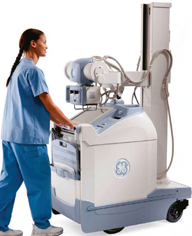
Mobile radiography using transportable radiographic equipment allows imaging services to be brought to the patient. In contrast to the large stationary machines found in radiographic rooms, compact mobile radiography units can produce diagnostic images in virtually any location (Fig. 28-1). Mobile radiography is commonly performed in patient rooms, emergency departments, intensive care units, surgery and recovery rooms, and nursery and neonatal units. Some machines are designed for transport by automobile or van to nursing homes, extended care facilities, or other off-site locations requiring radiographic imaging services.
Mobile radiography was first used by the military for treating battlefield injuries during World War I. Small portable units were designed to be carried by soldiers and set up in field locations. Although mobile equipment is no longer “carried” to the patient, the term portable has persisted and is often used in reference to mobile procedures.
This chapter focuses on the most common projections performed with mobile radiography machines. The basic principles of mobile radiography are described in detail, and helpful hints are provided for successful completion of the examinations. An understanding of common projections enables the radiographer to perform most mobile examinations ordered by the physician.
Mobile X-Ray Machines
Mobile x-ray machines are not as sophisticated as the larger stationary machines in the radiology department. Although mobile units are capable of producing images of most body parts, they vary in their exposure controls and power sources (or generators).
A typical mobile x-ray machine has controls for setting kilovolt (peak) (kVp) and milliampere-seconds (mAs). The mAs control automatically adjusts milliamperage (mA) and time to preset values. Maximum settings differ among manufacturers, but mAs typically range from 0.04 to 320 and kVp from 40 to 130. The total power of the unit ranges from 15 to 25 kilowatts (kW), which is adequate for most mobile projections. By comparison, the power of a stationary radiography unit can reach 150 kW (150 kVp, 1000 mA) or more.
Some mobile x-ray machines have preset anatomic programs (APRs) similar to stationary units. The anatomic programs use exposure techniques with predetermined values based on the selected examination. The radiographer can adjust these settings as needed to compensate for differences in the size or condition of a patient. Automatic exposure control (AEC) may be available for some mobile machines. A paddle containing an ionization chamber is placed behind the image receptor (IR) and is used to determine the exposure time. With the increasing use of computed radiography (CR), however, AEC may not be as useful. The much wider dynamic range available with CR and the ability to manipulate the final image with computer software results in images of proper density without the use of automatic systems.
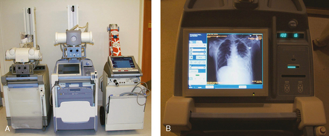
Some mobile units have direct digital capability, where the image is acquired immediately on the unit. These machines have a flat panel detector, similar to those found in a DR table Bucky. The detector either is connected to the portable unit by a tethered cord or communicates through wireless technology (Fig. 28-2).
Technical Considerations
Mobile radiography presents the radiographer with challenges different from those associated with performing examinations with stationary equipment in the radiology department. Although the positioning of the patient and placement of the central ray are essentially the same, three important technical matters must be clearly understood to perform optimal mobile examinations: the grid, the anode heel effect, and the source–to–image receptor distance (SID). In addition, exposure technique charts must be available (see Fig. 28-5).
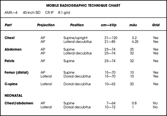
Fig. 28-5 Sample radiographic technique chart showing manual technical factors used for the 10 common mobile projections described in this chapter. The kVp and mAs factors are for the specific centimeter measurements indicated. Factors vary depending on the actual centimeter measurement.
GRID
Because the phosphor material used in CR imaging plates has higher absorption in the scattered x-ray energy range compared with screen-film, image quality degradation from scatter is more pronounced when using CR. Grid use is crucial in portable CR imaging.
For optimal imaging, a grid must be level, centered to the central ray, and correctly used at the recommended focal distance, or radius. When a grid is placed on an unstable surface such as the mattress of a bed, the weight of the patient can cause the grid to tilt “off-level.” If the grid tilts transversely while using a longitudinal grid, the central ray forms an angle across the long axis. Image density is lost as a result of grid “cutoff” (Fig. 28-3). If the grid tilts longitudinally, the central ray angles through the long axis. In this case, grid cutoff is avoided, but the image may be distorted or elongated.
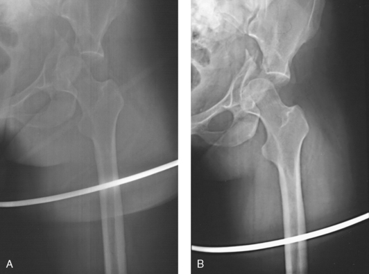
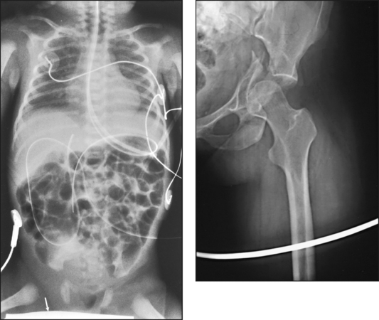
Fig. 28-3 Mobile radiograph of proximal femur and hip, showing comminuted fracture of left acetabulum. A, Poor-quality radiograph resulted when grid was transversely tilted far enough to produce significant grid cutoff. B, Excellent-quality repeat radiograph on the same patient, performed with grid accurately positioned perpendicular to central ray.
A grid positioned under a patient can be difficult to center. If the central ray is directed to a point transversely off the midline of a grid more than 1 to 1½ inches (2.5 to 3.8 cm), a cutoff effect similar to that produced by an off-level grid results. The central ray can be centered longitudinally to any point along the midline of a grid without cutoff. Depending on the procedure, beam-restriction problems may occur. If this happens, a portion of the image is “collimated off,” or patient exposure is excessive because of an oversized exposure field.
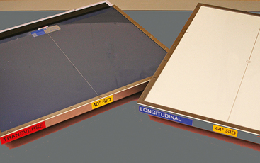
Grids used for mobile radiography are often of the focused type. Some radiology departments continue to use the older, parallel-type grids, however. All focused grids have a recommended focal range, or radius, that varies with the grid ratio. Projections taken at distances greater or less than the recommended focal range can produce cutoff in which image density is reduced on lateral margins. Grids with a lower ratio have a greater focal range, but they are less efficient for cleaning up scatter radiation. The radiographer must be aware of the exact focal range for the grid used. Most focused grids used for mobile radiography have a ratio of 6:1 or 8:1 and a focal range of about 36 to 44 inches (91 to 112 cm). This focal range allows mobile examinations to be performed efficiently. Inverting a focused grid causes a pronounced cutoff effect similar to that produced by improper distance.
Today most grids are mounted on a protective frame, and the IR is easily inserted behind the grid (Fig. 28-4). A final concern regarding grids relates to the use of “tape-on” grids. If a grid is not mounted on an IR holder frame but instead is manually fastened to the surface of the IR with tape, care must be taken to ensure that the tube side of the grid faces the x-ray tube. The examinations described in this chapter present methods of ensuring proper grid and IR placement for projections that require a grid.
ANODE HEEL EFFECT
Another consideration in mobile radiography is the anode heel effect. The heel effect causes a decrease of image density under the anode side of the x-ray tube. The heel effect is more pronounced with the following:
Short SIDs and large field sizes are common in mobile radiography. In mobile radiography, the radiographer has control of the anode-cathode axis of the x-ray tube relative to the body part. Correct placement of the anode-cathode axis with regard to the anatomy is essential. When performing a mobile examination, the radiographer may not always be able to orient the anode-cathode axis of the tube to the desired position because of limited space and maneuverability in the room. For optimal mobile radiography, the anode and cathode sides of the x-ray tube should be clearly marked to indicate where the high-tension cables enter the x-ray tube, and the radiographer should use the heel effect maximally (Table 28-1).
TABLE 28-1
Cathode placement for mobile projections
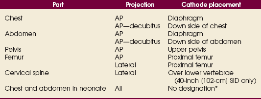
Note: The cathode side of the beam has the greatest intensity.
*Not necessary because of small field size of the collimator.
SOURCE–TO–IMAGE RECEPTOR DISTANCE
The SID should be maintained at 40 inches (102 cm) for most mobile examinations. A standardized distance for all patients and projections helps to ensure consistency in imaging. Longer SIDs—40 to 48 inches (102 to 122 cm)—require increased mAs to compensate for the additional distance. The mA limitations of a mobile unit necessitate longer exposure times when the SID exceeds 40 inches (102 cm). Despite the longer exposure time, a radiograph with motion artifacts may result if the SID is greater than 40 inches (102 cm). In addition, motion artifacts may occur in the radiographs of critically ill adult patients and infants or small children who require chest and abdominal examinations but may be unable to hold their breath.
RADIOGRAPHIC TECHNIQUE CHARTS
A radiographic technique chart should be available for use with every mobile machine. The chart should display, in an organized manner, the standardized technical factors for all the radiographic projections done with the machine (Fig. 28-5). A caliper should also be available; this device is used to measure the thickness of body parts to ensure that accurate and consistent exposure factors are used. Measuring the patient also allows the radiographer to determine the optimal kVp level for all exposures (Fig. 28-6).
Radiation Safety
Radiation protection for the radiographer, others in the immediate area, and the patient is of paramount importance when mobile examinations are performed. Mobile radiography produces some of the highest occupational radiation exposures for radiographers. The radiographer should wear a lead apron and stand as far away from the patient, x-ray tube, and useful beam as the room and the exposure cable allow. The recommended minimal distance is 6 ft (2 m). For a horizontal (cross-table) x-ray beam or for an upright anteroposterior (AP) chest projection, the radiographer should stand at a right angle (90 degrees) to the primary beam and the object being radiographed. The least amount of scatter radiation occurs at this position (Fig. 28-7). Shielding and distance have a greater effect on exposure reduction, however, and should always be considered first.
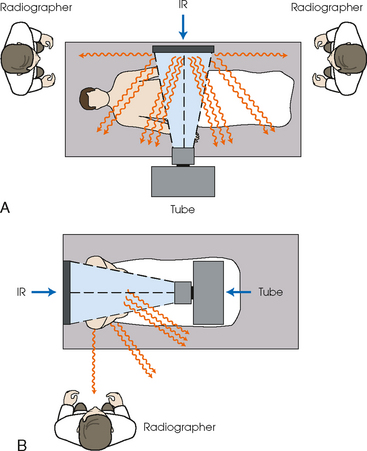
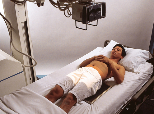
Fig. 28-7 Whenever possible, the radiographer should stand at least 6 ft (2 m) from the patient and useful beam. The lowest amount of scatter radiation occurs at a right angle (90 degrees) from the primary x-ray beam. A, Note radiographer standing at either the head or the foot of the patient at a right angle to the x-ray beam for dorsal decubitus position lateral projection of the abdomen. B, Radiographer standing at right angle to the x-ray beam for AP projection of the chest. IR, image receptor.
The most effective means of radiation protection is distance. The radiographer should inform all persons in the immediate area that an x-ray exposure is about to occur so that they may leave to avoid exposure. Lead protection should be provided for any individuals who are unable to leave the room and for individuals who may have to hold a patient or IR.
The patient’s gonads should be shielded with appropriate radiation protection devices for any of the following situations:
• X-ray examinations performed on children
• X-ray examinations performed on patients of reproductive age
• Any examination for which the patient requests protection
• Examinations in which the gonads lie in or near the useful beam
• Examinations in which shielding would not interfere with imaging of the anatomy that must be shown (Fig. 28-8)
In addition, the source-to-skin distance (SSD) cannot be less than 12 inches (30 cm), in accordance with federal safety regulations.1
Isolation Considerations
Two types of patients are often cared for in isolation units: (1) patients who have infectious microorganisms that could be spread to health care workers and visitors and (2) patients who need protection from potentially lethal microorganisms that may be carried by health care workers and visitors. Optimally, a radiographer entering an isolation room should have a full knowledge of the patient’s disease, the way it is transmitted, and the proper way to clean and disinfect equipment before and after use in the isolation unit. Because of the confidentiality of patient records, the radiographer may be unable to obtain information about a patient’s specific disease, however. All patients must be treated with universal precautions. If isolation is used to protect the patient from receiving microorganisms (reverse isolation), a different protocol may be required. Institutional policy regarding isolation procedures should be available and strictly followed.
When performing mobile procedures in an isolation unit, the radiographer should wear the required protective apparel for the specific situation—gown, cap, mask, shoe covers, and gloves. All of this apparel is not needed for every isolation patient. All persons entering a strict isolation unit wear a mask, a gown, and gloves, but only gloves are worn for drainage secretion precautions. Radiographers should always wash their hands with warm, soapy water before putting on gloves. The x-ray machine is taken into the room and moved into position. The IR is placed into a clean, protective cover. Pillowcases would not protect the IR or the patient if body fluids soak through them. A clean, impermeable cover should be used in situations in which body fluids may come into contact with the IR. For examinations of patients in strict isolation, two radiographers may be required to maintain a safe barrier (see Chapter 1).
After finishing the examination, the radiographer should remove and dispose of the mask, cap, gown, shoe covers, and gloves according to institutional policies. All equipment that touched the patient or the patient’s bed must be wiped with a disinfectant according to appropriate aseptic technique. The radiographer should wear new gloves, if necessary, while cleaning equipment. Handwashing is repeated before the radiographer leaves the room.
Performing Mobile Examinations
The radiographer should plan for the trip out of the radiology department. Ensuring that all of the necessary devices (e.g., IR, grid, tape, caliper, markers, blocks) are transported with the mobile x-ray machine provides greater efficiency in performing examinations. Many mobile x-ray machines are equipped with a storage area for transporting IRs and supplies. If a battery-operated machine is used, the radiographer should check the machine to ensure that it is acceptably charged. An inadequately charged machine can interfere with performance and affect the quality of the radiograph.
Before entering the patient’s room with the machine, the radiographer should follow several important steps (Box 28-1). The radiographer begins by checking that the correct patient is going to be examined. After confirming the identity of the patient, the radiographer enters, makes an introduction as a radiographer, and informs the patient about the x-ray examinations to be performed. While in the room, the radiographer observes any medical appliances, such as chest tube boxes, catheter bags, and intravenous (IV) poles, that may be positioned next to or hanging on the sides of the patient’s bed. The radiographer should ask family members or visitors to step out of the room until the examination is finished. If necessary, the nursing staff should be alerted that assistance is required.
Communication and cooperation between the radiographer and nursing staff members are essential for proper patient care during mobile radiography. In addition, communication with the patient is imperative, even if the patient is or appears to be unconscious or unresponsive.
EXAMINATION
Chairs, stands, IV poles, wastebaskets, and other obstacles should be moved from the path of the mobile machine. Lighting should be adjusted if necessary. If the patient is to be examined in the supine position, the base of the mobile machine should be positioned toward the middle of the bed. If a seated patient position is used, the base of the machine should be toward the foot of the bed.
For lateral and decubitus radiographs, positioning the base of the mobile machine parallel to or directly perpendicular to the bed allows the greatest ease in positioning the x-ray tube. Room size can also influence the base position used.
The radiographer sometimes may have difficulty accurately aligning the x-ray tube parallel to the IR while standing at the side of the bed. When positioning the tube above the patient, the radiographer may need to check the x-ray tube and IR alignment from the foot of the bed to ensure that the tube is not tilted.
For all projections, the primary x-ray beam must be collimated no larger than the size of the IR. When the central ray is correctly centered to the IR, the light field coincides with or fits within the borders of the IR.
A routine and consistent system for labeling and separating exposed and unexposed IRs should be developed and maintained. It is easy to “double expose” IRs during mobile radiography, particularly if many examinations are performed at one time. Most institutions require additional identification markers for mobile examinations. Typically the time of examination (especially for chest radiographs) and technical notes such as the position of the patient are indicated. A log may be maintained for each patient and kept in the patient’s room. The log should contain the exposure factors used for the projections and other notes regarding the performance of the examination.
PATIENT CONSIDERATIONS
Patients requiring mobile radiography often are in extended care facilities or are immobile and among the most sick. They may be awake and lying in bed in traction because of a broken limb, or they may be critically ill and unconscious. A brief but total assessment of the patient must be conducted before and during the examination. Some specific considerations to keep in mind are described in the following sections.
Assessment of the patient’s condition
A thorough assessment of the patient’s condition and room allows the radiographer to make necessary adaptations to ensure the best possible patient care and imaging outcome. The radiographer assesses the patient’s level of alertness and respiration and determines the extent to which the patient is able to cooperate and the limitations that may affect the procedure. Some patients may have varying degrees of drowsiness because of their medications or medical condition. Many mobile examinations are performed in patients’ rooms immediately after surgery; these patients may be under the influence of various anesthetics.
Patient mobility
The radiographer must never move a patient or part of the patient’s body without assessing the patient’s ability to move or tolerate movement. Gentleness and caution must prevail at all times. If unsure, the radiographer should always check with the nursing staff or physician. Many patients who undergo total joint replacement may be unable to move the affected joint for many days or weeks, but this may not be evident to the radiographer. Some patients may be able to indicate verbally their ability to move or their tolerance for movement. The radiographer should never move a limb that has been operated on or is broken, unless the nurse, the physician, or sometimes the patient grants permission. Inappropriate movement of the patient by the radiographer during the examination may harm the patient.
Fractures
Patients can have various fractures and fracture types, ranging from one simple fracture to multiple fractures of many bones. A patient lying awake in a traction bed with a simple femur fracture may be able to assist with a radiographic examination. Another patient may be unconscious and have multiple broken ribs, spinal fractures, or a severe closed head injury.
Few patients with multiple fractures are able to move or tolerate movement. The radiographer must be cautious, resourceful, and work in accordance with the patient’s condition and pain tolerance. If a patient’s trunk or limb must be raised into position for a projection, the radiographer should have ample assistance so that the part can be raised safely without causing harm or intense pain.
Interfering devices
Patients who are in intensive care units or orthopedic beds because of fractures may be attached to various devices, wires, and tubing. These objects may be in the direct path of the x-ray beam and consequently produce artifacts on the image. Experienced radiographers know which of these objects can be moved out of the x-ray beam. When devices such as fracture frames cannot be moved, it may be necessary to angle the central ray or adjust the IR to obtain the best radiograph possible. In many instances, the objects have to be radiographed along with the body part (Fig. 28-9). The radiographer must exercise caution when handling any of these devices and should never remove traction devices without the assistance of a physician.
Positioning and asepsis
During positioning, the IR (with or without a grid) often is perceived by the patient as cold, hard, and uncomfortable. Before the IR is put in place, the patient should be warned of possible discomfort and assured that the examination will be for as short a time as possible. The patient appreciates the radiographer’s concern and efficiency in completing the examination as quickly as possible.
If the surface of the IR touches bare skin, it can stick, making positioning adjustments difficult. The skin of older patients may be thin and dry and can be torn by manipulation of the IR if care is not taken. A cloth or paper cover over the IR can protect the patient’s skin and alleviate some of the discomfort by making it feel less cold. The cover also helps to keep the IR clean. IRs that contact the patient directly should be wiped off with a disinfectant for asepsis and infection control.
The IR must be enclosed in an appropriate, impermeable barrier in any situation in which it may come in contact with blood, body fluids, and other potentially infectious material. A contaminated IR can be difficult and sometimes impossible to clean. Approved procedures for disposing of used barriers must be followed.
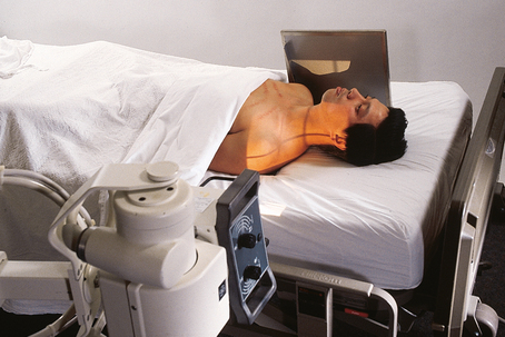
Chest
AP PROJECTION*
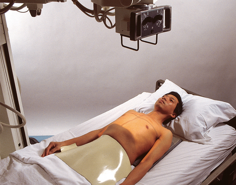
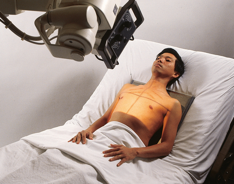
Upright or supine
Image receptor: 14 × 17 inch (35 × 43 cm) lengthwise or crosswise, depending on body habitus
Position of patient: Depending on the condition of the patient, elevate the head of the bed to a semierect or sitting position. The projection should be performed with the patient in the upright position or to the greatest angle tolerated by the patient whenever possible. Use the supine position for critically ill or injured patients.
• Center the midsagittal plane to the IR.
• To include the entire chest, position the IR under the patient with the top about 2 inches (5 cm) above the relaxed shoulders. The exact distance depends on the size of the patient. When the patient is supine, the shoulders may move to a higher position relative to the lungs. Adjust accordingly.
• Ensure that the patient’s shoulders are relaxed; then internally rotate the patient’s arms to prevent scapular superimposition of the lung field, if not contraindicated.
• Ensure that the patient’s upper torso is not rotated or leaning toward one side (Fig. 28-10).
• Respiration: Inspiration, unless otherwise requested. If the patient is receiving respiratory assistance, carefully watch the patient’s chest to determine the inspiratory phase for the exposure.

A grid must be used for all mobile computed radiography chest examinations if the exposure technique is more than 90 kVp. (Review the manufacturer’s protocol for the exact kVp levels for the unit that is used.) When a crosswise-positioned grid is used, the central ray must be perpendicular to the grid to prevent grid cutoff.
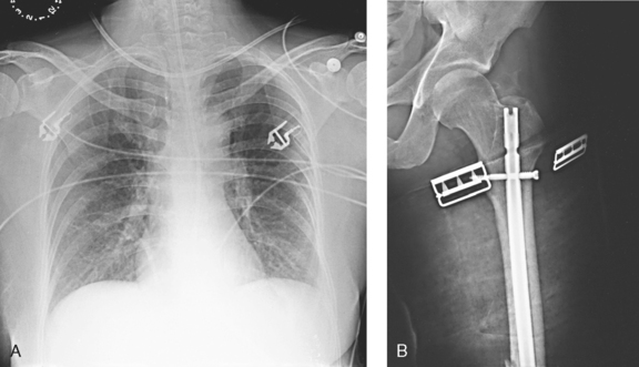
Structures shown: This projection shows the anatomy of the thorax, including the heart; trachea; diaphragmatic domes; and, most importantly, the entire lung fields, including vascular markings (Fig. 28-11).
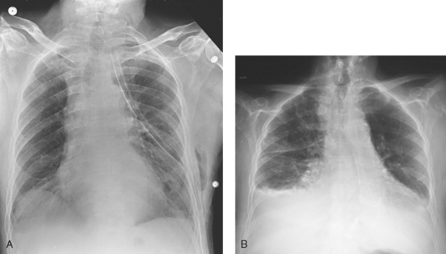
Fig. 28-11 Mobile AP chest radiographs in critically ill patients. A, Patient with postoperative left thoracotomy and chest tube, infiltrate or atelectasis in the left base, segmental elevation of the right hemidiaphragm, and soft tissue emphysema on the left. B, Patient with small left pleural effusion and moderate right effusion, cardiomegaly, mild pulmonary vascular congestion, and calcification and torsion of the aorta.
The following should be clearly shown:
 Evidence of proper collimation
No motion; well-defined (not blurred) diaphragmatic domes and lung fields
Lung fields in their entirety, including costophrenic angles
Ribs and thoracic intervertebral disk spaces faintly visible through heart shadow
No rotation, with medial portion of clavicles and lateral border of ribs equidistant from vertebral column
NOTE: To ensure the proper angle from the x-ray tube to the IR, the radiographer can double-check the shadow of the shoulders from the field light projected onto the IR. If the shadow of the shoulders is thrown far above the upper edge of the IR, the angle of the tube must be corrected.
AP OR PA PROJECTION*
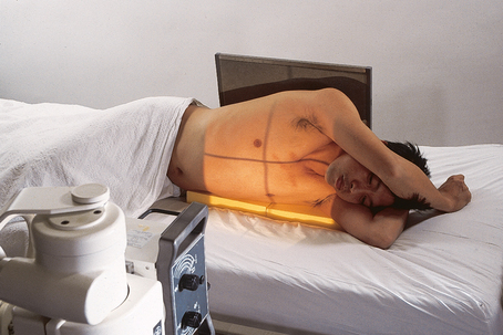
Right or left lateral decubitus position
Image receptor: 14 × 17 inch (35 × 43 cm) lengthwise grid IR
• Place the patient in the lateral recumbent position.
• Flex the patient’s knees to provide stabilization, if possible.
• Place a firm support under the patient to elevate the body 2 to 3 inches (5 to 8 cm) and prevent the patient from sinking into the mattress.
• Raise both of the patient’s arms up and away from the chest region, preferably above the head. An arm lying on the patient’s side can imitate a region of free air.
• Position the patient for the AP projection whenever possible. It is much easier to position an ill patient (particularly the arms) for an AP.
• Adjust the patient to ensure a lateral position. The coronal plane passing through the shoulders and hips should be vertical.
• Place the IR behind the patient and below the support so that the lower margin of the chest is visualized.
• Adjust the grid so that it extends approximately 2 inches (5 cm) above the shoulders. The IR should be supported in position and not leaning against the patient to avoid distortion (Fig. 28-12).
Structures shown: This projection shows the anatomy of the thorax, including the entire lung fields and any air or fluid levels that may be present (Fig. 28-13).
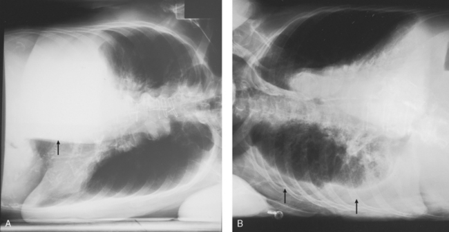
Fig. 28-13 Mobile AP chest radiographs performed in lateral decubitus positions in critically ill patients. A, Left lateral decubitus position. The patient has a large right pleural effusion (arrow) and no left effusion. Complete left side of thorax is visualized because of elevation on a block. B, Right lateral decubitus position. The patient has right pleural effusion (arrows), cardiomegaly, and mild pulmonary vascular congestion. Complete right side of thorax is visualized because of elevation on a block.
The following should be clearly shown:
Evidence of proper collimation
Affected side in its entirety (upper lung for free air and lower lung for fluid)
Patient’s arms out of region of interest
Proper identification to indicate that decubitus position was used
NOTE: Fluid levels in the pleural cavity are best visualized with the affected side down, which also prevents mediastinal overlapping. Air levels are best visualized with the unaffected side down. The patient should be in position for at least 5 minutes before the exposure is made to allow air to rise and fluid levels to settle.
Abdomen
AP PROJECTION*
Image receptor: 14 × 17 inch (35 × 43 cm) lengthwise grid
• Position the grid under the patient to show the abdominal anatomy from the pubic symphysis to the upper abdominal region.
• Keep the grid from tipping side to side by placing it in the center of the bed and stabilizing it with blankets or towels if necessary.
• Use the patient’s draw sheet to roll the patient; this makes it easier to shift the patient from side to side during positioning of the IR, and it provides a barrier between the patient’s skin and the grid.
• Center the midsagittal plane of the patient to the midline of the grid.
• Center the grid to the level of the iliac crests. If the emphasis is on the upper abdomen, center the grid 2 inches (5 cm) above the iliac crests or high enough to include the diaphragm.
• Adjust the patient’s shoulders and pelvis to lie in the same plane (Fig. 28-14).
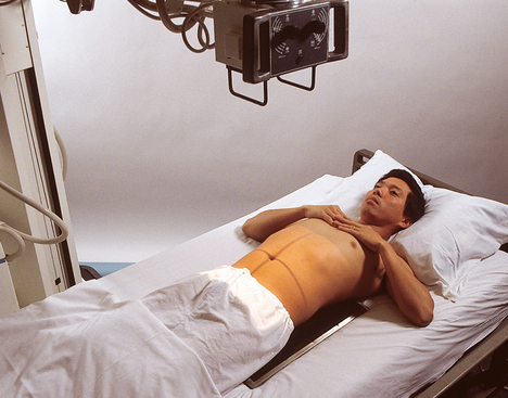
• Move the patient’s arms out of the region of the abdomen.
• Shield gonads. This may not be possible in a female patient.
Structures shown: This projection shows the following: the inferior margin of the liver; the spleen, kidneys, and psoas muscles; calcifications; and evidence of tumor masses. If the image includes the upper abdomen and diaphragm, the size and shape of the liver may be seen (Fig. 28-15).
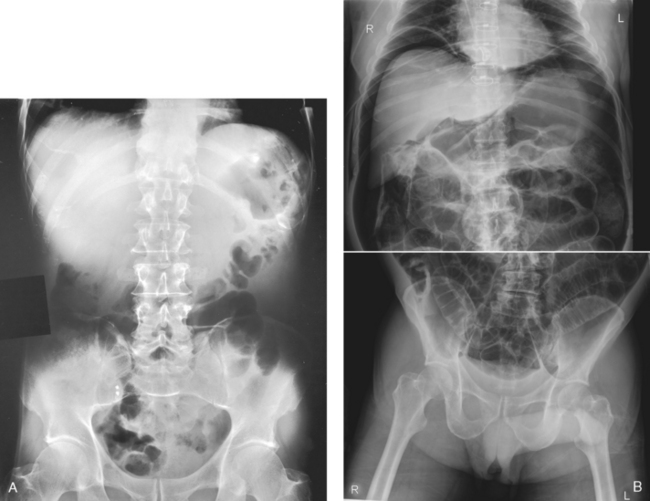
Fig. 28-15 Mobile AP abdomen radiographs. A, Abdomen without pathology. The entire abdomen is seen in this patient. B, Because of this patient’s increased body habitus, two crosswise (landscape) images of the abdomen were necessary to include all abdominal structures. Counting vertebral bodies ensures adequate overlap. Note large amount of free air indicative of a perforated bowel.
The following should be clearly shown:
Evidence of proper collimation
Outlines of the abdominal viscera
Abdominal region, including pubic symphysis or diaphragm (both may be seen on some patients)
Vertebral column in center of image
NOTE: Hypersthenic patients may require two separate projections using a crosswise grid. One grid is positioned for the upper abdomen, and the other is positioned for the lower abdomen.
AP OR PA PROJECTION*
Left lateral decubitus position
Image receptor: 14 × 17 inch (35 × 43 cm) lengthwise grid
• Place the patient in the left lateral recumbent position unless requested otherwise.
• Flex the patient’s knees slightly to provide stabilization.
• If necessary, place a firm support under the patient to elevate the body and keep the patient from sinking into the mattress.
• Raise both of the patient’s arms away from the abdominal region, if possible. The right arm lying on the side of the abdomen may imitate a region of free air.
• Use the PA or AP projection, depending on the room layout.
• Adjust the patient to ensure a true lateral position. The coronal plane passing through the shoulders and hips should be vertical.
• Place the grid vertically in front of the patient for a PA projection and behind the patient for an AP projection. The grid should be supported in position and not leaned against the patient; this position prevents grid cutoff.
• Position the grid so that its center is 2 inches (5 cm) above the iliac crests to ensure that the diaphragm is included. The pubic symphysis and lower abdomen do not have to be visualized (Fig. 28-16).
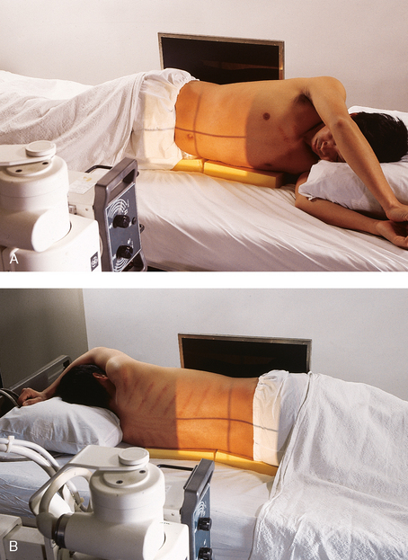
Fig. 28-16 Mobile AP abdomen: left lateral decubitus position. A, AP projection. B, PA projection. Note yellow blocks placed under abdomen to level abdomen and keep the patient from sinking into the mattress.
• Before making the exposure, ensure that the patient has been in the lateral recumbent position for at least 5 minutes to allow air to rise and fluid levels to settle.
Structures shown: Air or fluid levels within the abdominal cavity are shown. These projections are especially helpful in assessing free air in the abdomen. The right border of the abdominal region must be visualized (Fig. 28-17).
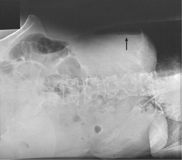
Fig. 28-17 Mobile AP abdomen: left lateral decubitus position. Free intraperitoneal air is seen on the upper or right side of the abdomen (arrow). The radiograph is slightly underexposed to show free air more easily.
The following should be clearly shown:
Evidence of proper collimation
Well-defined diaphragm and abdominal viscera
Air or fluid levels, if present
NOTE: Hypersthenic patients may require two projections with the 14- × 17-inch (35- × 43-cm) grid positioned crosswise to visualize the entire abdominal area. A patient with a long torso may require two projections with the grid lengthwise to visualize the entire abdominal region.
Pelvis
AP PROJECTION*
Image receptor: 14 × 17 inch (35 × 43 cm) grid crosswise
• Position the grid under the pelvis so that the center is midway between the anterior superior iliac spine (ASIS) and the pubic symphysis. This is about 2 inches (5 cm) inferior to the ASIS and 2 inches (5 cm) superior to the pubic symphysis.
• Center the midsagittal plane of the patient to the midline of the grid. The pelvis should not be rotated.
• Rotate the patient’s legs medially approximately 15 degrees when not contraindicated (Fig. 28-18).
• Shield gonads: This may not be possible in female patients.
Structures shown: This projection shows the pelvis, including the following: both hip bones; the sacrum and coccyx; and the head, neck, trochanters, and proximal portion of the femora (Fig. 28-19).
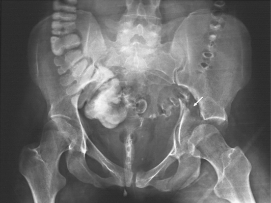
Fig. 28-19 Mobile AP pelvis. This patient has a comminuted fracture of the left acetabulum with medial displacement of medial acetabular wall (arrow). Residual barium is seen in the colon, sigmoid, and rectum.
The following should be clearly shown:
Evidence of proper collimation
Entire pelvis, including proximal femora and both hip bones
Symmetric appearance of iliac wings and obturator foramina
Both greater trochanters and ilia equidistant from edge of radiograph
Femoral necks not foreshortened and greater trochanters in profile
NOTE: It is common for the weight of the patient to cause the bottom edge of the grid to tilt upward. The x-ray tube may need to be angled caudally to compensate and maintain proper grid alignment, preventing grid cutoff. The exact angle needed is not always known, however, or easy to determine. The radiographer may want to lower the foot of the bed slightly (Fowler position), shifting the patient’s weight more evenly on the grid and allowing it to be flat. A rolled-up towel or blanket placed under the grid also may be useful to prevent lateral tilting. If the bed is equipped with an inflatable air mattress, the maximum inflate mode is recommended. Tilting the bottom edge of the grid downward is another possibility. Check the level of the grid carefully and compensate accordingly.
Femur
AP PROJECTION*
Most mobile AP and lateral projections of the femur may be radiographs of the middle and distal femur taken while the patient is in traction. The femur cannot be moved, which presents a challenge to the radiographer.
Image receptor: 14 × 17 inch (35 × 43 cm) grid lengthwise
• Cautiously place the grid lengthwise under the patient’s femur, with the distal edge of the grid low enough to include the fracture site, pathologic region, and knee joint.
• Elevate the grid with towels, blankets, or blocks under each side, if necessary, to ensure proper grid alignment with the x-ray tube.
• Center the grid to the midline of the affected femur.
• Ensure that the grid is placed parallel to the plane of the femoral condyles (Fig. 28-20).
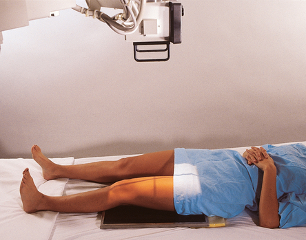
• Adjust to top at ASIS for hip, bottom at tibial tuberosity for knee, 1 inch (2.5 cm) on side of the shadow of the femur, and 17 inches (43 cm) in length.
The thickest portion of the femur (proximal area) must be carefully measured, and an appropriate kVp must be selected to penetrate this area. The computer cannot form an image of the anatomy in this area if penetration does not occur. A light area of the entire proximal femur would result. Positioning the cathode over the proximal femur would improve CR image quality.
Structures shown: The distal two thirds of the femur, including the knee joint, are shown (Fig. 28-21).
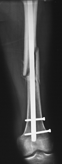
Fig. 28-21 Mobile AP femur radiograph showing a fracture of the midshaft with femoral rod placement. The knee joint is included on the image.
The following should be clearly shown:
Evidence of proper collimation
Most of femur, including knee joint
NOTE: If the entire length of the femur needs to be visualized, an AP projection of the proximal femur can be performed by placing a 14- × 17-inch (35- × 43-cm) grid lengthwise under the proximal femur and hip. The top of the grid is placed at the level of the ASIS to ensure that the hip joint is included. The central ray is directed to the center of the grid and long axis of the femur (see Fig. 28-3).
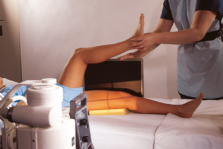
LATERAL PROJECTION*
Mediolateral projection
• Visualize the optimal length of the patient’s femur by placing the grid in a vertical position next to the lateral aspect of the femur.
• Place the distal edge of the grid low enough to include the patient’s knee joint.
• Have the patient, if able, hold the upper corner of the grid for stabilization; otherwise, support the grid firmly in position.
• Support the unaffected leg by using the patient’s support (a trapeze bar if present) or a support block.
• Elevate the unaffected leg until the femur is nearly vertical. An assistant may need to elevate and hold the leg of a critically ill patient. The assistant may also steady the grid and must wear a lead apron for protection (Fig. 28-22).
Lateromedial projection
• Place the grid next to the medial aspect of the affected femur (between the patient’s legs), and ensure that the knee joint is included (Fig. 28-23).
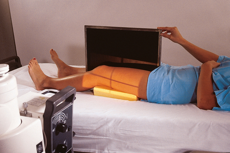
Fig. 28-23 Mobile lateromedial left femur. Grid is placed between the legs and steadied by the patient.
• Ensure that the grid is placed perpendicular to the epicondylar plane.
• Adjust to top at ASIS for hip, bottom at tibial tuberosity for knee, 1 inch (2.5 cm) on side of the shadow of the femur, and 17 inches (43 cm) in length.
The thickest portion of the femur (proximal area) must be measured carefully, and an appropriate kVp must be selected to penetrate this area. The computer cannot form an image of any anatomy in this area if penetration does not occur. A light area of the entire proximal femur would result. Positioning the cathode over the proximal femur would improve CR image quality.
Structures shown: This projection shows the distal two thirds of the femur, including the knee joint, without superimposition of the opposite thigh (Fig. 28-24).
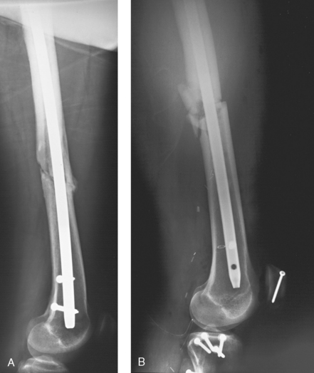
Fig. 28-24 Mobile lateral femur radiographs showing midshaft fractures and femoral rod placement. The knee joints are included on the image. A, Mediolateral. B, Lateromedial.
Cervical Spine
LATERAL PROJECTION*
Right or left dorsal decubitus position
Image receptor: 10 × 12 inch (24 × 30 cm) grid lengthwise; may be performed with a nongrid IR on smaller patients
• Ensure that the upper torso, cervical spine, and head are not rotated.
• Place the grid lengthwise on the right or left side, parallel to the neck.
• Place the top of the grid approximately 1 inch (2.43 cm) above the external acoustic meatus (EAM) so that the grid is centered to C4 (upper thyroid cartilage).
• Raise the chin slightly. In a patient with new trauma, suspected fracture, or known fracture of the cervical region, check with the physician before elevating the chin. Improper movement of a patient’s head can disrupt a fractured cervical spine.
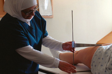
• Immobilize the grid in a vertical position. The grid can be immobilized in multiple ways if a holding device is unavailable. The best method is to use the measuring caliper. Slide the long portion of the caliper under the shoulders of the patient, with the short end of the caliper pointing toward the ceiling and the grid held between the ends of the caliper (Fig. 28-25). Another method is to place pillows or a cushion between the side rail of the bed and the IR, holding the IR next to the patient. Tape also works well in many instances (Fig. 28-26).
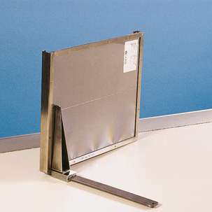
Fig. 28-25 Measuring caliper used to hold a 10- × 12-inch (24- × 30-cm) grid in place for mobile lateral cervical spine radiography.
• Have the patient relax the shoulders and reach for the feet, if possible.
• Respiration: Full expiration to obtain maximum depression of the shoulders.
• Horizontal and perpendicular to the center of the grid. This should place the central ray at the level of C4 (upper thyroid cartilage).
• Ensure that proper alignment of the central ray and grid is maintained to prevent grid cutoff.
• Because of the great object–to–image receptor distance (OID), SID of 60 to 72 inches (158 to 183 cm) is recommended. This also helps show C7.
• Adjust top at top of ear attachment (TEA), bottom to jugular notch, and 1 inch (2.5 cm) on sides of neck.
To ensure that the lower cervical vertebrae are fully penetrated, the kVp must be set to penetrate the C7 area.
Structures shown: This projection shows the seven cervical vertebrae, including the base of the skull and the soft tissues surrounding the neck (Fig. 28-27).
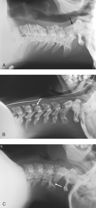
Fig. 28-27 Mobile lateral cervical spine radiographs performed at the patient’s bedside several weeks after trauma. A, Entire cervical spine shows slight anterior subluxation of the dens on the body of C2 (arrow). B, Entire cervical spine shows nearly vertical fracture through the body of C5 with slight displacement (arrow). C, First five cervical vertebrae show vertical fractures through posterior aspects of C2 laminae (arrow) with 4-mm displacement of the fragments. Earlier radiographs showed that C6 and C7 were unaffected and did not need to be included in this follow-up radiograph.
The following should be clearly shown:
Evidence of proper collimation
All seven cervical vertebrae, including interspaces and spinous processes
Neck extended when possible so that rami of mandible are not overlapping C1 or C2
NOTE: It is essential that C6 and C7 be included on the image. To accomplish this, the radiographer should instruct the patient to relax the shoulders toward the feet as much as possible. If the examination involves pulling down on the patient’s arms, the radiographer should exercise extreme caution and evaluate the patient’s condition carefully to determine whether pulling of the arms can be tolerated. Fractures or injuries of the upper limbs, including the clavicles, must be considered. Applying a strong pull to the arms of a patient in a hurried or jerking manner can disrupt a fractured cervical spine. If the lateral projection does not adequately visualize the lower cervical region, the Twining method, sometimes referred to as the “swimmer’s” position, which eliminates pulling of the arms, may be recommended for patients who have experienced trauma or have a known cervical fracture. One arm must be placed above the patient’s head (see description of Twining method in Chapter 8, Vol 1).
Chest and Abdomen: Neonate
The chest and abdomen combination described here is typically ordered for premature newborn infants who are in the neonatal intensive care unit. If a chest or abdomen projection is ordered separately, the radiographer should adjust the central ray and collimator accordingly.
Image receptor: 8 × 10 inch (20 × 24 cm) or 10 × 12 inch (24 × 30 cm) lengthwise
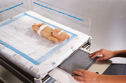
Position of patient: Position the infant supine in the center of the IR. Some bassinets have a special tray to hold the IR. Positioning numbers along the tray permits accurate placement of the IR (Fig. 28-28). If the IR is directly under the infant, cover the IR with a soft, warm blanket.
• Carefully position the x-ray tube over the infant (Fig. 28-29).

Fig. 28-29 Neonatal intensive care unit bassinet with a premature infant. Overhead heating unit (arrow) is moved out of the way to accommodate mobile x-ray machine tube head.
• Ensure that the chest and abdomen are not rotated.
• Move the infant’s arms away from the body or over the head and bring the legs down and away from the abdomen. The arms and legs may have to be held by a nurse, who should wear a lead apron.
• Leave the head of the infant rotated. (See note at end of this section.)
• Adjust the collimators closely to the chest and abdomen (Fig. 28-30).
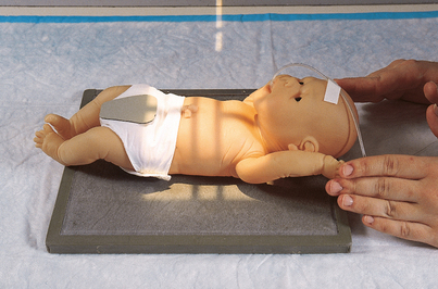
Fig. 28-30 Mobile chest and abdomen radiograph of a neonate. Note the male gonadal shield. (In actual practice, the IR is covered with a soft, warm blanket.)
• Respiration: Inspiration. Neonates have an extremely fast respiratory rate and cannot hold their breath. Make the best attempt possible to perform the exposure on full inspiration (Fig. 28-31).
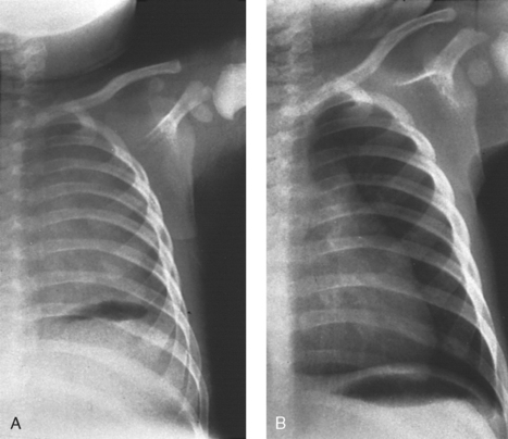
Fig. 28-31 Radiographs on inspiration and expiration in a neonate. A, Left side of chest is shown at full expiration. Note the lack of normal lung markings and the illusion of massive pulmonary disease. Diaphragm is not seen, and heart appears enlarged. B, Repeat radiograph of the same patient performed correctly at full inspiration. Diaphragm may be seen correctly at the level of the 10th posterior rib. The same technical factors were used for both exposures. (Courtesy Department of Radiology, Rochester General Hospital, Rochester, NY; from Cullinan AM, Cullinan JE: Producing quality radiographs, ed 2, Philadelphia, 1994, Lippincott.) Lippincott
Structures shown: The anatomy of the entire chest and abdomen is shown (Fig. 28-32).
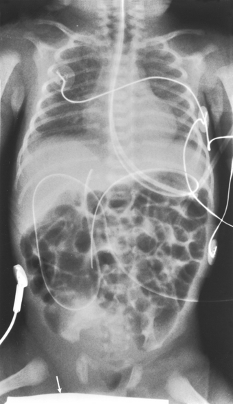
Fig. 28-32 Mobile AP chest and abdomen radiograph of a neonate. Exposure technique shows the anatomy of entire chest and abdomen. Note gonadal shield accurately positioned on this male infant (arrow).
The following should be clearly shown:
Evidence of proper collimation
Anatomy from apices to pubic symphysis in the thoracic and abdominal regions
NOTE: When performing an AP or lateral projection of the chest, the radiographer should keep the head and neck of the infant straight so that the anatomy in the upper chest and airway is accurately visualized. Straightening the head of a neonate in the supine position can inadvertently advance an endotracheal tube too far into the trachea, however. It is sometimes more important to leave the head of an intubated neonatal patient rotated in the position in which the infant routinely lies to obtain accurate representation of the position of the endotracheal tube on the radiograph.
LATERAL PROJECTION
Image receptor: 8 × 10 inch (20 × 24 cm) or 10 × 12 inch (24 × 30 cm) lengthwise. Most premature neonates cannot be turned on their sides or placed upright for a lateral projection.
• Ensure that the infant’s chest and abdomen are centered to the IR and not rotated.
• Move the infant’s arms above the head. The infant’s arms have to be held up by a nurse, who should wear a lead apron.
• Place the IR lengthwise and vertical beside the patient and immobilize it.
• Leave the head of the infant rotated. (See note on p. 196.)
• Adjust the collimators closely to the chest and abdomen (Fig. 28-33).
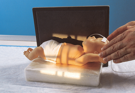
Fig. 28-33 Mobile lateral chest and abdomen radiograph of a neonate in dorsal decubitus position. The infant is positioned on a raised block with the IR below the block.
• Respiration: Inspiration. Neonates have an extremely fast respiratory rate and cannot hold their breath. Make the best attempt possible to perform the exposure on full inspiration.
Structures shown: This projection shows the anatomy of the entire chest and abdomen, with special attention to the costophrenic angles in the posterior chest. If present, air and fluid levels are visualized (Fig. 28-34).
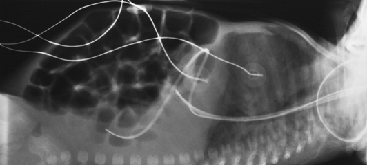
Fig. 28-34 Mobile lateral chest and abdomen radiograph of a neonate in dorsal decubitus position. Exposure technique shows the anatomy of the entire chest and abdomen.
Adler, AM, Carlton, RR. Introduction to radiography and patient care, ed 4. Philadelphia: Saunders, 2007.
Bontrager, KL. Textbook of radiographic positioning, ed 7. St Louis: Mosby, 2010.
Bushong, SC. Radiologic science for technologists, ed 9. St Louis: Mosby, 2008.
Ehrlich, RA, McClosky, ED. Patient care in radiography, ed 7. St Louis: Mosby, 2009.
Hall-Rollins, J, Winters, R. Mobile chest radiography: improving image quality. Radiol Technol. 2000;71:5.
Statkiewicz-Sherer, MA, et al. Radiation protection in medical radiography, ed 6. St Louis: Mosby, 2011.
Tucker, DM, et al. Scatter in computed radiography. Radiology. 1993;188:271.
1National Council on Radiation Protection: Report 102: Medical x-ray, electron beam and gamma ray protection for energies up to 50 MeV, Bethesda, MD, 1989.
*The nonmobile projection is described in Chapter 10.
*The nonmobile projection is described in Chapter 10.
*The nonmobile projection is described in Chapter 16.
*The nonmobile projection is described in Chapter 16.
*The nonmobile projection is described in Chapter 7.
*The nonmobile projection is described in Chapter 6.
*The nonmobile projection is described in Chapter 6.
*The nonmobile projection is described in Chapter 8.