ABDOMEN
SUMMARY OF PROJECTIONS

Abdominopelvic Cavity
The abdominopelvic cavity consists of two parts: (1) a large superior portion, the abdominal cavity, and (2) a smaller inferior part, the pelvic cavity. The abdominal cavity extends from the diaphragm to the superior aspect of the bony pelvis. The abdominal cavity contains the stomach, small and large intestines, liver, gallbladder, spleen, pancreas, and kidneys. The pelvic cavity lies within the margins of the bony pelvis and contains the rectum and sigmoid of the large intestine, the urinary bladder, and the reproductive organs.
The abdominopelvic cavity is enclosed in a double-walled seromembranous sac called the peritoneum. The outer portion of this sac, termed the parietal peritoneum, is in close contact with the abdominal wall, the greater (false) pelvic wall, and most of the undersurface of the diaphragm. The inner portion of the sac, known as the visceral peritoneum, is positioned over or around the contained organs. The peritoneum forms folds called the mesentery and omenta, which serve to support the viscera in position. The space between the two layers of the peritoneum is called the peritoneal cavity and contains serous fluid (Fig. 16-1). Because there are no mesenteric attachments of the intestines in the pelvic cavity, pelvic surgery can be performed without entry into the peritoneal cavity.
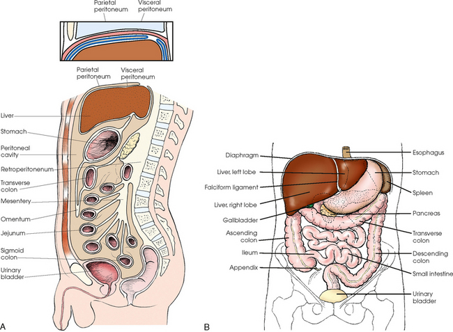
Fig. 16-1 A, Lateral aspect of abdomen showing peritoneal sac and its components. B, Anterior aspect of abdominal viscera in relation to surrounding structures.
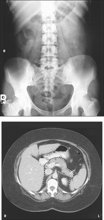
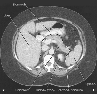
The retroperitoneum is the cavity behind the peritoneum. Organs such as the kidneys and pancreas lie in the retroperitoneum (Fig. 16-2).
Abdominal Radiographic Procedures
In examinations without a contrast medium, it is imperative to obtain maximal soft tissue differentiation throughout the different regions of the abdomen. Because of the wide range in the thickness of the abdomen and the delicate differences in physical density between the contained viscera, it is necessary to use a more critical exposure technique than is required to show the difference in density between an opacified organ and the structures adjacent to it. The exposure factors should be adjusted to produce a radiograph with moderate gray tones and less black-and-white contrast. If the kilovolt peak (kVp) is too high, the possibility of not showing small or semiopaque gallstones increases (Fig. 16-3, A).
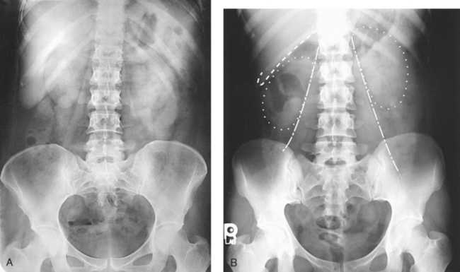
Fig. 16-3 A, AP abdomen showing proper positioning and collimation. B, AP abdomen showing kidney shadows (dotted line), margin of liver (dashed line), and psoas muscles (dot-dash lines).
Sharply defined outlines of the psoas muscles, the lower border of the liver, the kidneys, the ribs, and the transverse processes of the lumbar vertebrae are the best criteria for judging the quality of an abdominal radiograph (Fig. 16-3, B).
IMMOBILIZATION
A prime requisite in abdominal examinations is to prevent voluntary and involuntary movement. The following steps are observed:
• To prevent muscle contraction caused by tension, adjust the patient in a comfortable position so that he or she can relax.
• Explain the breathing procedure, and ensure the patient understands exactly what is expected.
• If necessary, apply a compression band across the abdomen for immobilization but not compression.
• Do not start the exposure for 1 to 2 seconds after the suspension of respiration to allow the patient to come to rest and involuntary movement of the viscera to subside.
Voluntary motion produces a blurred outline of the structures that do not have involuntary movement, such as the liver, psoas muscles, and spine. Patient breathing during exposure results in blurring of bowel gas outlines in the upper abdomen as the diaphragm moves (Fig. 16-4). Involuntary motion caused by peristalsis may produce either a localized or a generalized haziness of the image. Involuntary contraction of the abdominal wall or the muscles around the spine may cause movement of the entire abdominal area and produce generalized radiographic haziness.
Abdomen
Radiography of the abdomen may include one or more radiographic projections. The most commonly performed projection is the supine AP projection, often called a KUB because it includes the kidneys, ureters, and bladder. Projections used to complement the supine AP include an upright AP abdomen or an AP projection in the lateral decubitus position (the left lateral decubitus is most often preferred), or both. Both radiographs are useful in assessing the abdomen in patients with free air (pneumoperitoneum) and in determining the presence and location of air-fluid levels. Other abdominal projections include a lateral projection or a lateral projection in the supine (dorsal decubitus) body position. Many institutions also obtain a PA chest radiograph to include the upper abdomen and diaphragm. The PA chest radiograph is indicated because any air escaping from the gastrointestinal tract into the peritoneal space rises to the highest level, usually just beneath the diaphragm.
POSITIONING PROTOCOLS
Radiographs obtained to evaluate the patient’s abdomen vary considerably depending on the institution and physician. Some physicians consider the preliminary evaluation radiograph to consist of only the AP (supine) projection. Others obtain two projections: a supine and an upright AP abdomen (often called a flat and an upright). A three-way or acute abdomen series may be requested to rule out free air, bowel obstruction, and infections. The three projections usually include (1) AP with the patient supine, (2) AP with the patient upright, and (3) PA chest. If the patient cannot stand for the upright AP projection, the projection is performed using the left lateral decubitus position. The PA chest projection can be used to detect free air that may accumulate under the diaphragm.
Positioning for radiographs of the abdomen is described in the following pages. (For a description of positioning for the PA chest, see Chapter 10.)
Abdominal Sequencing
To show small amounts of intraperitoneal gas in acute abdominal cases, Miller1,2 recommended that the patient be kept in the left lateral position on a stretcher for 10 to 20 minutes before abdominal radiographs are obtained. This position allows gas to rise into the area under the right hemidiaphragm, where the image would not be superimposed by the gastric gas bubble. If larger amounts of free air are present, many radiology departments suggest that the patient lie on the side for a minimum of 5 minutes before the radiograph is produced.
Projections of the abdomen are taken as follows:
• Perform an AP or PA projection of the chest and upper abdomen with the patient in the left lateral decubitus position.
• Use the chest exposure technique for this radiograph (Fig. 16-5).
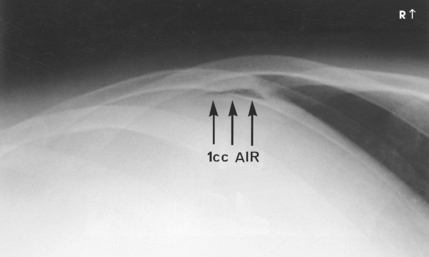
Fig. 16-5 Enlarged portion of AP abdomen, left lateral decubitus position in a patient injected with 1 mL of air into abdominal cavity.
• Maintain the patient in the left lateral decubitus position while the patient is being moved onto a horizontally placed table. Tilt the table and patient to the upright position.
• Turn the patient to obtain AP or PA projections of the chest and abdomen (Figs. 16-6 and 16-7).
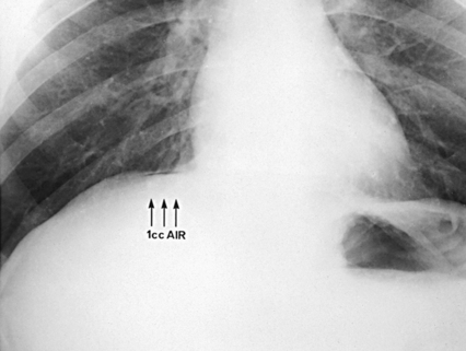
Fig. 16-6 Enlarged portion of upright AP chest showing free air in same patient as in Fig. 16-5.
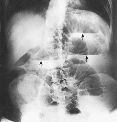
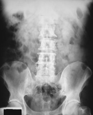
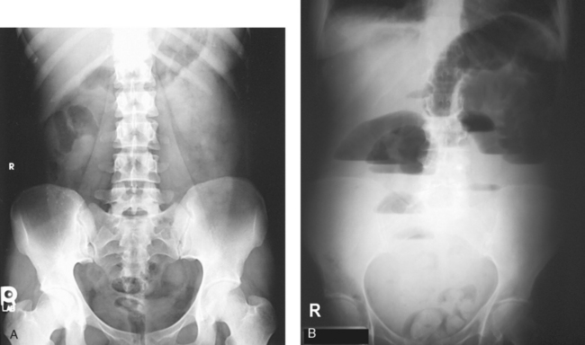
Fig. 16-7 AP abdomen, upright position, showing air-fluid levels (arrows) in intestine (same patient as in Fig. 16-8).
• Return the table back to the horizontal position for a supine AP or PA projection of the abdomen (Fig. 16-8).
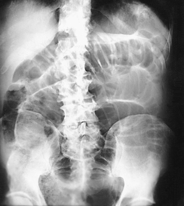
Fig. 16-8 AP abdomen. Supine study showing intestinal obstruction in same patient as in Fig. 16-7.
 AP PROJECTION
• Center the midsagittal plane of the body to the midline of the grid device.
• If the patient is upright, distribute the weight of the body equally on the feet.
• Place the patient’s arms where they do not cast shadows on the image.
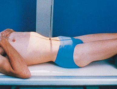
• With the patient supine, place a support under the knees to relieve strain.
• For the supine position, center the IR at the level of the iliac crests, and ensure that the pubic symphysis is included (Fig. 16-9).
• For the upright position, center the IR 2 inches (5 cm) above the level of the iliac crests or high enough to include the diaphragm (Fig. 16-10).
• If the bladder is to be included on the upright radiograph, center the IR at the level of the iliac crests.
• If a patient is too tall to include the entire pelvic area, obtain a second radiograph to include the bladder on a 10 × 12 inch (24 × 30 cm) IR if necessary. The 10 × 12 inch (24 × 30 cm) IR is placed crosswise and centered 2 to 3 inches (5 to 7.6 cm) above the upper border of the pubic symphysis.
• If necessary, apply a compression band across the abdomen with moderate pressure for immobilization.
• Shield gonads: Use local gonad shielding for examinations of male patients (not shown for illustrative purposes).
• Respiration: Suspend at the end of expiration so that the abdominal organs are not compressed.
Structures shown: AP projection of the abdomen shows the size and shape of the liver, the spleen, and the kidneys and intra-abdominal calcifications or evidence of tumor masses (Fig. 16-11). Additional examples of supine and upright abdomen projections are shown in Figs. 16-7 and 16-8.
The following should be clearly shown:
 Evidence of proper collimation
Area from the pubic symphysis to the upper abdomen (two radiographs may be necessary if the patient is tall)
Proper patient alignment, as ensured by the following:
No rotation of patient, as indicated by the following:
 Spinous processes in the center of the lumbar vertebrae
Soft tissue gray tones showing the following:
Lateral abdominal wall and preperitoneal fat layer (flank stripe)
Psoas muscles, lower border of the liver, and kidneys
Transverse processes of the lumbar vertebrae
Right or left marker visible but not lying over abdominal contents
Diaphragm without motion on upright abdominal examinations (crosswise IR placement is appropriate if the patient is large).
Density on upright abdominal examination, similar to supine examination; however, reduce density if pneumoperitoneum suspected
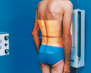
PA PROJECTION
When the kidneys are not of primary interest, the upright PA projection should be considered. Compared with the AP projection, the PA projection of the abdomen greatly reduces patient gonadal dose.
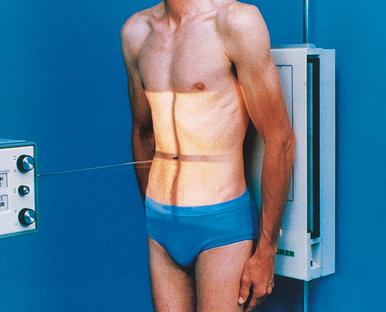
• With the patient in the upright position, place the anterior abdominal surface in contact with the vertical grid device.
• Center the abdominal midline to the midline of the IR.
• Center the IR 2 inches (5 cm) above the level of the iliac crests (Fig. 16-12), as previously described for the upright AP projection. The central ray, structures shown, and evaluation criteria are the same as for the upright AP projection.
AP PROJECTION
• If the patient is too ill to stand, place him or her in a lateral recumbent position lying on a radiolucent pad on a transportation cart. Use a left lateral decubitus position in most situations.
• If possible, have the patient lie on the side for several minutes before the exposure to allow air to rise to its highest level within the abdomen.
• Place the patient’s arms above the level of the diaphragm so that they are not projected over any abdominal contents.
• Flex the patient’s knees slightly to provide stabilization.
• Exercise care to ensure that the patient does not fall off the cart; if a cart is used, lock all wheels securely in position.
• Adjust the height of the vertical grid device so that the long axis of the IR is centered to the midsagittal plane.
• Position the patient so that the level of the iliac crests is centered to the IR. A slightly higher centering point, 2 inches (5 cm) above the iliac crests, may be necessary to ensure that the diaphragms are included in the image (Fig. 16-13).
• Adjust the patient to ensure that a true lateral position is attained.
 COMPENSATING FILTER
For patients with large abdomens, a compensating filter improves image quality by preventing overexposure of the upper-side abdominal area.
• Adjust to 14 × 17 inches (35 × 43 cm) on the collimator. For smaller patients, collimate to within 1 inch (2.5 cm) of shadow of the abdomen.
NOTE: A right lateral decubitus position is often requested or may be required when the patient cannot lie on the left side.
Structures shown: In addition to showing the size and shape of the liver, spleen, and kidneys, the AP abdomen with the patient in the left decubitus position is most valuable for showing free air and air-fluid levels when an upright abdomen projection cannot be obtained (Fig. 16-14).
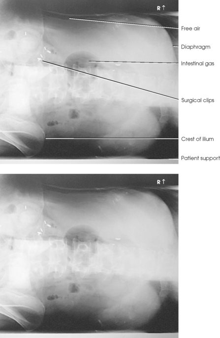
Fig. 16-14 AP abdomen, left lateral decubitus position showing free air collection along right flank. Note correct marker placement.
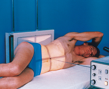
LATERAL PROJECTION
• Flex the patient’s knees to a comfortable position, and adjust the body so that the midcoronal plane is centered to the midline of the grid.
• Place supports between the knees and the ankles.
• Flex the elbows, and place the hands under the patient’s head (Fig. 16-15).

• Center the IR at the level of the iliac crests or 2 inches (5 cm) above the crests to include the diaphragm.
• Place a compression band across the pelvis for stability if necessary.
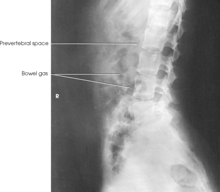
Structures shown: A lateral projection of the abdomen shows the prevertebral space occupied by the abdominal aorta and any intra-abdominal calcifications or tumor masses (Fig. 16-16).
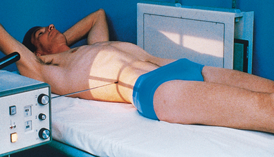
LATERAL PROJECTION
R or L dorsal decubitus position
• When the patient cannot stand or lie on the side, place the patient in the supine position on a transportation cart or other suitable support with the right or left side in contact with the vertical grid device.
• Place the patient’s arms across the upper chest to ensure they are not projected over any abdominal contents, or place them behind the patient’s head.
• Flex the patient’s knees slightly to relieve strain on the back.
• Exercise care to ensure that the patient does not fall from the cart or table; if a cart is used, lock all wheels securely in position.
• Adjust the height of the vertical grid device so that the long axis of the IR is centered to the midcoronal plane.
• Position the patient so that a point approximately 2 inches (5 cm) above the level of the iliac crests is centered to the IR (Fig. 16-17).
• Adjust the patient to ensure no rotation from the supine position occurs.
Structures shown: The lateral projection of the abdomen is valuable in showing the prevertebral space and is quite useful in determining air-fluid levels in the abdomen (Fig. 16-18).
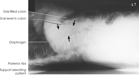
Fig. 16-18 Lateral abdomen, left dorsal decubitus position, showing calcified aorta (arrows). Note correct marker placement.