URINARY SYSTEM AND VENIPUNCTURE
SUMMARY OF PROJECTIONS
Urinary System
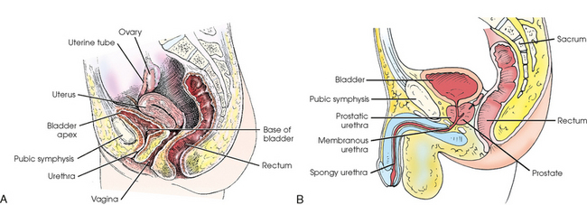
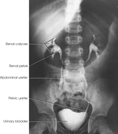
The urinary system includes two kidneys, two ureters, one urinary bladder, and one urethra (Figs. 18-1 and 18-2). The functions of the kidneys include removing waste products from the blood, maintaining fluid and electrolyte balance, and secreting substances that affect blood pressure and other important body functions. The kidneys normally excrete 1 to 2 L of urine per day. Urine is expelled from the body via the excretory system, as the urinary system is often called. The excretory system consists of the following:
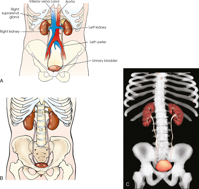
Fig. 18-1 Anterior aspect of urinary system in relation to surrounding structures. A, Abdominal structures. B, Bony structures. C, Three-dimensional CT image of urinary system in relation to bony structures.
• A variable number of urine-draining branches in the kidney called the calyces and an expanded portion called the renal pelvis, which together are known as the pelvicaliceal system
• Two long tubes called ureters, with one ureter extending from the pelvis of each kidney
• A saclike portion, the urinary bladder, which receives the distal portion of the ureters and serves as a reservoir
• A third and smaller tubular portion, the urethra, which conveys the urine to the exterior of the body
Suprarenal Glands
Closely associated with the urinary system are the two suprarenal, or adrenal, glands. These ductless endocrine glands have no functional relationship with the urinary system but are included in this chapter because of their anatomic relationship with the kidneys. Each suprarenal gland consists of a small, flattened body composed of an internal medullary portion and an outer cortical portion. Each gland is enclosed in a fibrous sheath and is situated in the retroperitoneal tissue in close contact with the fatty capsule overlying the medial and superior aspects of the upper pole of the kidney. The suprarenal glands furnish two important substances: (1) epinephrine, which is secreted by the medulla, and (2) the cortical hormones, which are secreted by the cortex. These glands are subject to malfunction and numerous diseases. They are not usually shown on preliminary radiographs but are delineated when computed tomography (CT) is used. The suprarenal circulation may be shown by selective catheterization of a suprarenal artery or vein in angiographic procedures.
Kidneys
The kidneys are bean-shaped bodies. The lateral border of each kidney is convex, and the medial border is concave. They have slightly convex anterior and posterior surfaces, and they are arbitrarily divided into upper and lower poles. The kidneys are approximately 4½ inches (11.5 cm) long, 2 to 3 inches (5 to 7.6 cm) wide, and about 1¼ inches (3 cm) thick. The left kidney usually is slightly longer and narrower than the right kidney.
The kidneys are situated behind the peritoneum (retroperitoneal) and are in contact with the posterior wall of the abdominal cavity, one kidney lying on each side of and in the same coronal plane with L3. The superior aspect of the kidney lies more posterior than the inferior aspect (see Fig. 18-2). Each kidney lies in an oblique plane and is rotated about 30 degrees anteriorly toward the aorta, which lies on top of the vertebral body (Fig. 18-3). When the body is rotated 30 degrees for the AP oblique projection (LPO or RPO position), the lower kidney lies perpendicular and the upper kidney lies parallel to the IR. The kidneys normally extend from the level of the superior border of T12 to the level of the transverse processes of L3 in sthenic individuals; they are higher in individuals with a hypersthenic habitus and lower in persons with an asthenic habitus. Because of the large space occupied by the liver, the right kidney is slightly lower in position than the left kidney.
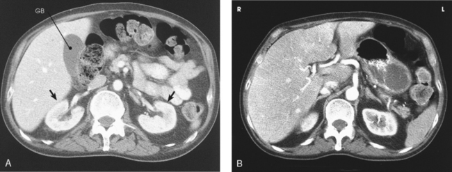
Fig. 18-3 A, Axial CT image through center of kidney. Note 30-degree anterior angulation of kidneys (arrows). GB, gallbladder. B, Axial CT image of upper abdomen. Note superior aspect of right kidney and midportion of left kidney showing lower placed left kidney. (From Kelley LL, Petersen CM: Sectional anatomy for imaging professionals, ed 2, St Louis, 2007, Mosby.)
The outer covering of the kidney is called the renal capsule. The capsule is a semitransparent membrane that is continuous with the outer coat of the ureter. Each kidney is embedded in a mass of fatty tissue called the adipose capsule. The capsule and kidney are enveloped in a sheath of superficial fascia, the renal fascia, which is attached to the diaphragm, lumbar vertebrae, peritoneum, and other adjacent structures. The kidneys are supported in a fairly fixed position, partially through the fascial attachments and partially by the surrounding organs. They have a respiratory movement of approximately 1 inch (2.5 cm) and normally drop no more than 2 inches (5 cm) in the change from supine to upright position.
The concave medial border of each kidney has a longitudinal slit, or hilum, for transmission of the blood and lymphatic vessels, nerves, and ureter (Fig. 18-4). The hilum expands into the body of the kidney to form a central cavity called the renal sinus. The renal sinus is a fat-filled space surrounding the renal pelvis and vessels.
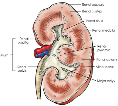
Each kidney has an outer renal cortex and an inner renal medulla. The renal medulla, composed mainly of the collecting tubules that give it a striated appearance, consists of 8 to 15 cone-shaped segments called the renal pyramids. The apices of the segments converge toward the renal sinus to drain into the pelvicaliceal system. The more compact renal cortex lies between the periphery of the organ and the bases of the medullary segments and extends medially between the pyramids to the renal sinus. These extensions of the cortex are called renal columns.
The essential microscopic components of the parenchyma of the kidney are called nephrons (Fig. 18-5). Each kidney contains approximately 1 million of these tubular structures. The individual nephron is composed of a renal corpuscle and a renal tubule. The renal corpuscle consists of a double-walled membranous cup called the glomerular capsule (Bowman capsule) and a cluster of blood capillaries called the glomerulus. The glomerulus is formed by a minute branch of the renal artery entering the capsule and dividing into capillaries. The capillaries turn back and, as they ascend, unite to form a single vessel leaving the capsule.
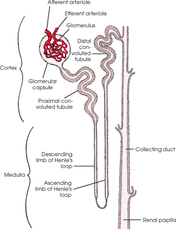
The vessel entering the capsule is called the afferent arteriole, and the one leaving the capsule is termed the efferent arteriole. After exiting the glomerular capsules, the efferent arterioles form the capillary network surrounding the straight and convoluted tubules, and these capillaries reunite and continue on to communicate with the renal veins.
The thin inner wall of the capsule closely adheres to the capillary coils and is separated by a comparatively wide space from the outer layer, which is continuous with the beginning of a renal tubule. The glomerulus serves as a filter for the blood, permitting water and finely dissolved substances to pass through the walls of the capillaries into the capsule. The change from filtrate to urine is caused in part by the water and the usable dissolved substances being absorbed through the epithelial lining of the tubules into the surrounding capillary network.
Each renal tubule continues from a glomerular capsule in the cortex of the kidney and then travels a circuitous path through the cortical and medullary substances, becoming the proximal convoluted tubule, the nephron loop (loop of Henle), and the distal convoluted tubule. The distal convoluted tubule opens into the collecting ducts that begin in the cortex. The collecting ducts converge toward the renal pelvis and unite along their course so that each group within the pyramid forms a central tubule that opens at a renal papilla and drains its tributaries into the minor calyx.
The calyces are cup-shaped stems arising at the sides of the papilla of each renal pyramid. Each calyx encloses one or more papillae, so that there are usually fewer calyces than pyramids. The beginning branches are called the minor calyces (numbering from 4 to 13), and they unite to form two or three larger tubes called the major calyces. The major calyces unite to form the expanded, funnel-shaped renal pelvis. The wide, upper portion of the renal pelvis lies within the hilum, and its tapering lower part passes through the hilum to become continuous with the ureter. This area where the renal pelvis transitions to the ureter is called the ureteropelvic junction (UPJ).
Ureters
Each ureter is 10 to 12 inches (25 to 30 cm) long. The ureters descend behind the peritoneum and in front of the psoas muscle and the transverse processes of the lumbar vertebrae, pass inferiorly and posteriorly in front of the sacral wing, and then curve anteriorly and medially to enter the posterolateral surface of the urinary bladder at approximately the level of the ischial spine. The ureters convey the urine from the renal pelves to the bladder by slow, rhythmic peristaltic contractions.
Urinary Bladder
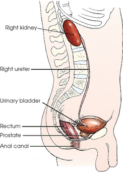
The urinary bladder is a musculomembranous sac that serves as a reservoir for urine. The bladder is situated immediately posterior and superior to the pubic symphysis and is directly anterior to the rectum in the male and anterior to the vaginal canal in the female. The apex of the bladder is at the anterosuperior aspect and is adjacent to the superior aspect of the pubic symphysis. The most fixed part of the bladder is the neck, which rests on the prostate in the male and on the pelvic diaphragm in the female.
The bladder varies in size, shape, and position according to its content. It is freely movable and is held in position by folds of the peritoneum. When empty, the bladder is located in the pelvic cavity. As the bladder fills, it gradually assumes an oval shape while expanding superiorly and anteriorly into the abdominal cavity. The adult bladder can hold approximately 500 mL of fluid when completely full. The urge for micturition (urination) occurs when about 250 mL of urine is in the bladder.
The ureters enter the posterior wall of the bladder at the lateral margins of the superior part of its base and pass obliquely through the wall to their respective internal orifices (Fig. 18-6). This portion of each ureter, where it joins the bladder, is called the ureterovesical junction (UVJ). These two openings are about 1 inch (2.5 cm) apart when the bladder is empty and about 2 inches (5 cm) apart when the bladder is distended. The openings are equidistant from the internal urethral orifice, which is situated at the neck (lowest part) of the bladder. The triangular area between the three orifices is called the trigone. The mucosa over the trigone is always smooth, whereas the remainder of the lining contains folds, called rugae, when the bladder is empty.
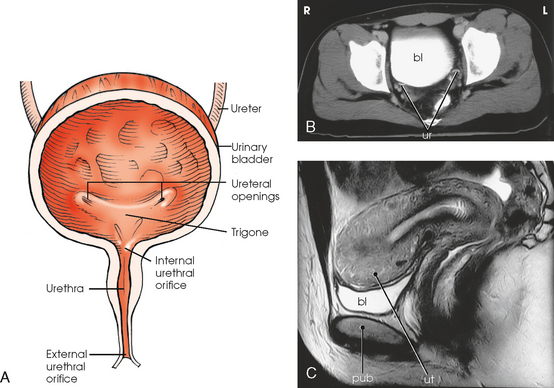
Fig. 18-6 A, Anterior view of urinary bladder. B, Axial CT image of pelvis showing contrast medium–filled bladder (bl) and ureters (ur). C, Sagittal MRI of female pelvis showing contrast medium–filled bladder (bl) and relationship to uterus (ut) and pubis (pub). (B and C, From Kelley LL, Petersen CM: Sectional anatomy for imaging professionals, ed 2, St Louis, 2007, Mosby.)
Urethra
The urethra, which conveys the urine out of the body, is a narrow, musculomembranous tube with a sphincter type of muscle at the neck of the bladder. The urethra arises at the internal urethral orifice in the urinary bladder and extends about 1½ inches (3.8 cm) in the female and 7 to 8 inches (17.8 to 20 cm) in the male.
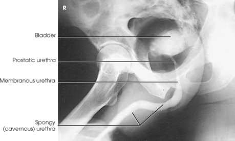
The female urethra passes along the thick anterior wall of the vagina to the external urethral orifice, which is located in the vestibule about 1 inch (2.5 cm) anterior to the vaginal opening (see Fig. 18-6). The male urethra extends from the bladder to the the penis and is divided into prostatic, membranous, and spongy portions (Fig. 18-7). The prostatic portion is about 1 inch (2.5 cm) long, reaches from the bladder to the floor of the pelvis, and is completely surrounded by the prostate. The membranous portion of the canal passes through the urogenital diaphragm; it is slightly constricted and about ½ inch (1.3 cm) long. The spongy portion passes through the shaft of the penis, extending from the floor of the pelvis to the external urethral orifice. The distal prostatic, membranous, and spongy parts of the male urethra also serve as the excretory canal of the reproductive system.
Prostate
The prostate is a small glandular body surrounding the proximal part of the male urethra and is situated just posterior to the inferior portion of the pubic symphysis. The prostate is considered part of the male reproductive system, but because of its close proximity to the bladder it is commonly described with the urinary system. The conical base of the prostate is attached to the inferior surface of the urinary bladder, and its apex is in contact with the pelvic diaphragm. The prostate measures about 1½ inches (3.8 cm) transversely and ¾ inch (1.9 cm) anteroposteriorly at its base; vertically the prostate is approximately 1 inch (2.5 cm) long. The prostate gland secretes a milky fluid that combines with semen from the seminal vesicles and vas deferens. These secretions enter the urethra via ducts in the prostatic urethra.
SUMMARY OF PATHOLOGY
| Condition | Definition |
| Benign prostatic hyperplasia (BPH) | Enlargement of prostate |
| Calculus | Abnormal concretion of mineral salts, often called a stone |
| Carcinoma | Malignant new growth composed of epithelial cells |
| Bladder | Carcinoma located in the bladder |
| Renal cell | Carcinoma located in the kidney |
| Congenital anomaly | Abnormality present since birth |
| Duplicate collecting system | Two renal pelves or ureters from the same kidney |
| Horseshoe kidney | Fusion of the kidneys, usually at the lower poles |
| Pelvic kidney | Kidney that fails to ascend and remains in the pelvis |
| Cystitis | Inflammation of the bladder |
| Fistula | Abnormal connection between two internal organs or between an organ and the body surface |
| Glomerulonephritis | Inflammation of the capillary loops in the glomeruli of the kidney |
| Hydronephrosis | Distention of renal pelvis and calyces with urine |
| Polycystic kidney | Massive enlargement of the kidney with the formation of many cysts |
| Pyelonephritis | Inflammation of the kidney and renal pelvis |
| Renal hypertension | Increased blood pressure to the kidneys |
| Renal obstruction | Condition preventing normal flow of urine through the urinary system |
| Stenosis | Narrowing or contraction of a passage |
| Tumor | New tissue growth where cell proliferation is uncontrolled |
| Wilms | Most common childhood abdominal neoplasm affecting the kidney |
| Ureterocele | Ballooning of the lower end of the ureter into bladder |
| Vesicoureteral reflux | Backward flow of urine from the bladder into the ureters |
EXPOSURE TECHNIQUE CHART ESSENTIAL PROJECTIONS
Overview
The role of radiography in evaluation of the urinary system is changing, as other imaging modalities are increasing in use. Multidetector CT, with three-dimensional reconstruction capabilities, has improved visualization of small pathologies that were difficult or impossible to see on radiographs. Radiography of the urinary system comprises numerous specialized procedures, each of which requires the use of an iodinated contrast medium and each of which was developed to serve a specific purpose.
The specialized procedures are preceded by a plain, or scout, radiograph of the abdominopelvic areas for the detection of abnormalities that can be shown on plain radiography. The preliminary examination may consist of only an AP projection of the abdomen. When indicated, oblique or lateral projections or both are taken to localize calcifications, such as urinary calculi or phleboliths (pelvic vein calcifications), and tumor masses, and an upright position may be used to show the mobility of the kidneys.
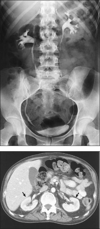
Preliminary radiography can usually show the position and mobility of the kidneys and usually their size and shape because of the contrast furnished by the radiolucent fatty capsule surrounding the kidneys. In addition, properly selected CT soft tissue windows can show the renal parenchyma without contrast media (Fig. 18-8). Visualization of the thin-walled drainage, or collecting, system (calyces and pelves, ureters, urinary bladder, and urethra) requires that the canals be filled with a contrast medium. The urinary bladder is outlined when it is filled with urine, but it is not adequately shown. The ureters and the urethra cannot be distinguished on preliminary radiographs. A CT “stone protocol” without contrast medium can clearly show calcified renal stones (Fig. 18-9).
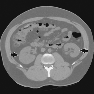
Fig. 18-8 CT of abdomen without contrast media showing parenchyma and renal pelvis of both kidneys (arrows). (Courtesy Karl Mockler, RT[R].)
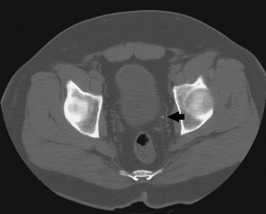
Fig. 18-9 CT “stone protocol” without contrast media showing renal calculus in left distal ureter (arrow). (Courtesy Karl Mockler, RT[R].)
CONTRAST STUDIES
To delineate and differentiate cysts and tumor masses situated within the kidney, the renal parenchyma is opacified by an intravenously introduced organic, iodinated contrast medium and then radiographed by tomography (Fig. 18-10) or CT (Fig. 18-11). The contrast solution may be introduced into the vein by rapid injection or by infusion.
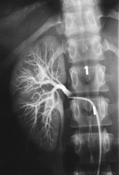
Angiographic procedures are used to investigate the blood vessels of the kidneys and the suprarenal glands (see Chapter 25, Volume 3). An example of the direct injection of contrast medium into the renal artery is shown in Fig. 18-12.
Radiologic investigations of the renal drainage, or collecting, system are performed by various procedures classified under the general term urography. This term embraces two regularly used techniques for filling the urinary canals with a contrast medium. Imaging of cutaneous urinary diversions has been described by Long.1
Antegrade filling
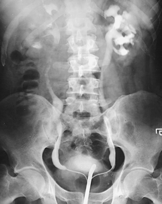
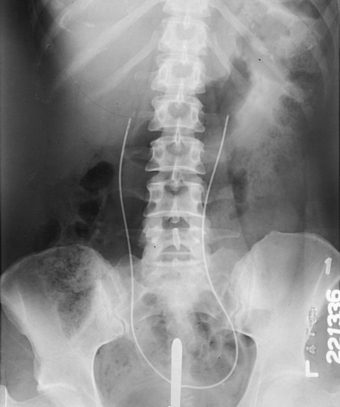
Antegrade filling techniques allow the contrast medium to enter the kidney in the normal direction of blood flow. In selective patients, this is done by introducing the contrast material directly into the kidney through a percutaneous puncture of the renal pelvis—a technique called percutaneous antegrade urography. Much more commonly used is the physiologic technique, in which the contrast agent is generally administered intravenously. This technique is called excretory or intravenous urography (IVU) and is shown in Fig. 18-13.
IVU is used in examinations of the upper urinary tract in infants and children and is generally considered to be the preferred technique in adults unless use of the retrograde technique is definitely indicated. Because the contrast medium is administered intravenously and all parts of the urinary system are normally shown, the excretory technique is correctly referred to as IVU. The term pyelography refers to the radiographic demonstration of the renal pelves and calyces. This examination has been erroneously called an intravenous pyelogram (IVP).
After the opaque contrast medium enters the bloodstream, it is conveyed to the renal glomeruli and is discharged into the capsules with the glomerular filtrate, which is excreted as urine. With the reabsorption of water, the contrast material becomes sufficiently concentrated to render the urinary canals radiopaque. The urinary bladder is well outlined by this technique, and satisfactory voiding urethrograms may be obtained.
Retrograde filling
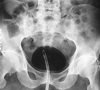
In some procedures involving the urinary system, the contrast material is introduced against the normal flow. This is called retrograde urography (Fig. 18-14). The contrast medium is injected directly into the canals via ureteral catheterization for contrast filling of the upper urinary tract and via urethral catheterization for contrast filling of the lower part of the urinary tract. Cystoscopy is required to localize the vesicoureteral orifices for the passage of ureteral catheters.
Retrograde urographic examination of the proximal urinary tract is primarily a urologic procedure. Catheterization and contrast filling of the urinary canals are performed by the attending urologist in conjunction with a physical or endoscopic examination. This technique enables the urologist to obtain catheterized specimens of urine directly from each renal pelvis. Because the canals can be fully distended by direct injection of the contrast agent, the retrograde urographic examination sometimes provides more information about the anatomy of the different parts of the collecting system than can be obtained by the excretory technique. For the retrograde procedure, an evaluation of kidney function depends on an intravenously administered dye substance to stain the color of the urine that subsequently trickles through the respective ureteral catheters. The antegrade and retrograde techniques of examination are occasionally required for a complete urologic study.
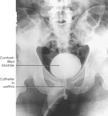
Investigations of the lower urinary tract—bladder, lower ureters, and urethra—are usually done by the retrograde technique, which requires no instrumentation beyond passage of a urethral catheter. Investigations may also be done by the physiologic technique (Figs. 18-15 and 18-16). Bladder examinations are usually denoted by the general term cystography (Fig. 18-17). A procedure that includes inspection of the lower ureters is cystoureterography (Fig. 18-18), and a procedure that includes inspection of the urethra is cystourethrography (Fig. 18-19).
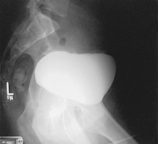
Fig. 18-15 Voiding study after routine injection IVU. Dilation of proximal urethra (arrows) is the result of urethral stricture.
Fig. 18-16 Voiding studies of same patient as in Fig. 18-15 after infusion nephrourography. Note increase in opacification of contrast medium–filled cavities by this method and bladder diverticulum (arrows).
Contrast media
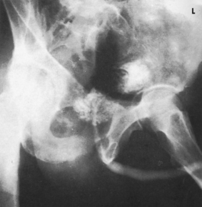
Retrograde urography (Figs. 18-20 and 18-21) was first performed in 1904 with the introduction of air into the urinary bladder. In 1906, retrograde urography and cystography were performed with the first opaque medium, a colloidal silver preparation that is no longer used. Silver iodide, which is a nontoxic inorganic compound, was introduced in 1911. Sodium iodide and sodium bromide, also inorganic compounds, were first used for retrograde urography in 1918. The bromides and iodides are no longer widely used for examinations of the renal pelves and ureters because they irritate the mucosa and commonly cause considerable patient discomfort.
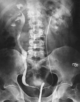
Fig. 18-20 Retrograde urogram with contrast medium–filled right renal pelvis and catheter in left renal pelvis.
Because a large quantity of solution is required to fill the urinary bladder, iodinated salts in concentrations of 30% or less are used in cystography. A large selection of commercially available contrast media may be used for all types of radiographic examinations of the urinary system. It is important to review the product insert packaged with every contrast agent.
Excretory urography (Figs. 18-22 and 18-23) was first reported by Rowntree et al. in 1923.1 These investigators used a 10% solution of chemically pure sodium iodide as the contrast medium. This agent was excreted too slowly, however, to show the renal pelves and ureters satisfactorily, and it proved too toxic for functional distribution. Early in 1929, Roseno and Jepkins2 introduced a compound containing sodium iodide and urea. The latter constituent, which is one of the nitrogenous substances removed from the blood and eliminated by the kidneys, served to accelerate excretion and to fill the renal pelves with opacified urine quickly. Although satisfactory renal images were obtained with this compound, patients experienced considerable distress as a result of its toxicity.
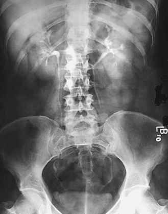
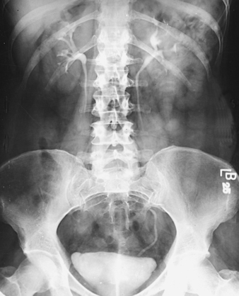
Fig. 18-23 Excretory urogram on same patient as in Fig. 18-22, 25 minutes after contrast medium injection.
In 1929, Swick developed the organic compound Uroselectan, which had an iodine content of 42%. The present-day ionic contrast media for excretory urography are the result of extensive research by many investigators. These media are available under various trade names in concentrations ranging from approximately 50% to 70%. Sterile solutions of the media are supplied in dose-size ampules or vials.
In the early 1970s, research was initiated to develop nonionic contrast media. Development progressed, and several nonionic contrast agents are currently available for urographic, vascular, and intrathecal injection. Although nonionic contrast media are generally less likely to cause a reaction in the patient, they are twice as expensive as ionic agents.
Many institutions have developed criteria to determine which patient receives which contrast medium. The choice of whether to use an ionic or nonionic contrast medium depends on patient risk and economics.
Adverse reactions to iodinated media
The iodinated organic preparations that are compounded for urologic examinations are of low toxicity. Consequently, adverse reactions are usually mild and of short duration. Common reactions are a feeling of warmth and flushing. Occasionally, nausea, vomiting, a few hives, and edema of the respiratory mucous membrane result. Severe and serious reactions occur only rarely but are always a possibility. The clinical history of each patient must be carefully checked, and the patient must be kept under careful observation for any sign of systemic reactions. According to the 2008 version of the American College of Radiology (ACR) Manual on Contrast Media, “nearly all life-threatening reactions occur immediately or within 20 minutes after contrast media injection.” The patient should not be left unattended during this time period. Emergency equipment and medication (diphenhydramine, epinephrine) to treat adverse reactions must be readily available. The ACR additionally states that the radiologist on-site during the procedure must be prepared and able to treat these reactions.
Preparation of intestinal tract
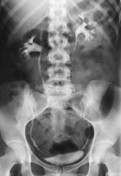
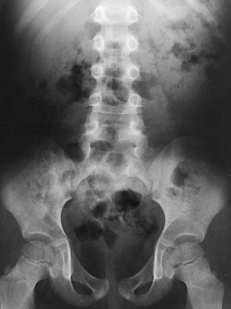
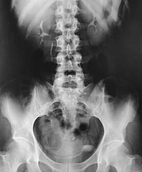
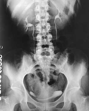
Although unobstructed visualization of the urinary tracts requires that the intestinal tract be free of gas and solid fecal material (Fig. 18-24), bowel preparation is not attempted in infants and children. The use of cleansing measures in adults depends on the condition of the patient. Gas (particularly swallowed air, which is quickly dispersed through the small bowel) rather than fecal material usually interferes with the examination.
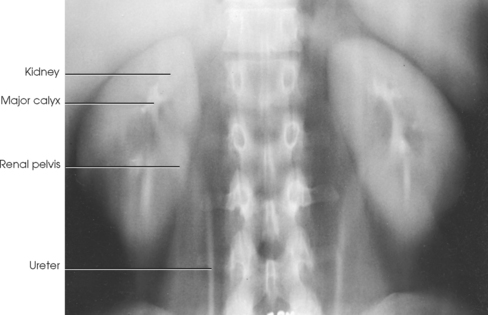
Hope and Campoy1 recommended that infants and children be given a carbonated soft drink to distend the stomach with gas. By this maneuver, the gas-containing intestinal loops are usually pushed inferiorly, and the upper urinary tracts, particularly on the left side of the body, are clearly visualized through the outline of the gas-filled stomach. Hope and Campoy stated that the aerated drink should be given in an amount adequate to inflate the stomach fully: at least 2 oz. is required for a newborn infant, and 12 oz. is required for a 7-year-old child. In conjunction with the carbonated drink, Hope and Campoy recommended using a highly concentrated contrast medium. A gas-distended stomach is shown in Fig. 18-25.
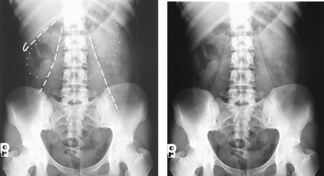
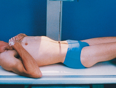
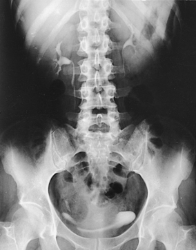
Berdon et al.2 stated that the prone position resolves the problem of obscuring gas in most patients (Figs. 18-26 and 18-27). It is unnecessary to inflate the stomach with air alone or with air as part of an aerated drink. By exerting pressure on the abdomen, the prone position moves the gas laterally away from the pelvicaliceal structures. Gas in the antral portion of the stomach is displaced into its fundic portion, gas in the transverse colon shifts into the ascending and descending segments, and gas in the sigmoid colon shifts into the descending colon and rectum. These investigators noted, however, that the prone position occasionally fails to produce the desired result in small infants when the small intestine is dilated. Gastric inflation also fails in these patients because the dilated small intestine merely elevates the gas-filled stomach and does not improve visualization. They recommended examination of such infants after the intestinal gas has passed.
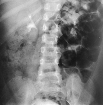
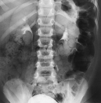
Fig. 18-27 Urogram: prone position, in the same patient as in Fig. 18-26. Visualization of left kidney and ureter is markedly improved.
Preparation of patient
Medical opinion concerning patient preparation varies widely. With modifications as required, the following procedure seems to be in general use:
• When time permits, have the patient follow a low-residue diet for 1 to 2 days to prevent gas formation caused by excessive fermentation of the intestinal contents.
• Have the patient eat a light evening meal on the day before the examination.
• When indicated by costive bowel action, administer a non–gas-forming laxative the evening before the examination.
• Have the patient take nothing by mouth after midnight on the day of the examination. The patient should not be dehydrated, however. Patients with multiple myeloma, high uric acid levels, or diabetes must be well hydrated before IVU is performed; these patients are at increased risk for contrast medium– induced renal failure if they are dehydrated.
• In preparation for retrograde urography, have the patient drink a large amount of water (4 or 5 cups) several hours before the examination to ensure excretion of urine in an amount sufficient for bilateral catheterized specimens and renal function tests.
• No patient preparation is usually necessary for examinations of the lower urinary tract.
Outpatients should be given explicit directions regarding any order from the physician pertaining to diet, fluid intake, and laxatives or other medication. The patient should also be given a suitable explanation for each preparative measure to ensure cooperation.
EQUIPMENT
A combination cystoscopic-radiographic unit facilitates retrograde urographic procedures requiring cystoscopy. Any standard radiographic table is suitable to perform preliminary excretory urography and most retrograde studies of the bladder and urethra. The cystoscopic unit is also used for these procedures; however, for the patient’s comfort, the table should have an extensible leg rest.
Infusion nephrourography requires a table equipped with tomographic apparatus. Tomography should be performed when intestinal gas obscures some of the underlying structures or when hypersthenic patients are being examined (Figs. 18-28 to 18-30).
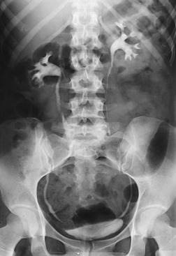
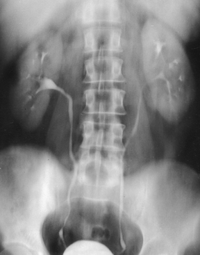
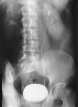
Fig. 18-30 Urogram: AP oblique projection, LPO position, using tomography. Note left kidney is perpendicular to IR.
For the patient’s comfort and to prevent delays during the examination, all preparations for the examination should be completed before the patient is placed on the table. In addition to an identification and side marker, excretory urographic studies require a time interval marker for each postinjection study. Body position markers (supine, prone, upright or semiupright, Trendelenburg, decubitus) should also be used.
Some institutions perform excretory urograms (proximal urinary tract studies) using a 10- × 12-inch (24- × 30-cm) IR placed crosswise, but these studies can also be made on 14- × 17-inch (35- × 43-cm) IRs placed lengthwise. The upright study is made on a 14- × 17-inch (35- × 43-cm) IR because it is taken to show the mobility of the kidneys and to outline the lower ureters and bladder. Studies of the bladder before and after voiding are usually taken on 10- × 12-inch (24- × 30-cm) IRs.
The following guidelines are observed in preparing additional equipment for the examination:
• Have an emergency cart fully equipped and conveniently placed.
• Arrange the instruments for injection of the contrast agent on a small, movable table or on a tray.
• Have frequently used sterile items readily available. Disposable syringes and needles are available in standard sizes and are widely used in this procedure.
• Have required nonsterile items available: a tourniquet, a small waste basin, an emesis basin, general disposable wipes, one or two bottles of contrast medium, and a small prepared dressing for application to the puncture site.
• Have iodine or alcohol wipes available.
• Provide a folded towel or a small pillow that can be placed under the patient’s elbow to relieve pressure during the injection.
PROCEDURE
Image quality and exposure technique
Urograms should have the same contrast, density, and degree of soft tissue density as abdominal radiographs. The radiographs must show a sharply defined outline of the kidneys, lower border of the liver, and lateral margin of the psoas muscles. The amount of bone detail visible in these studies varies according to the thickness of the abdomen (Fig. 18-31).
Motion control
An immobilization band usually is not applied over the upper abdomen in urographic examinations because the resultant pressure may interfere with the passage of fluid through the ureters and may cause distortion of the canals. The elimination of motion in urographic examinations depends on the exposure time and on securing the full cooperation of the patient.
The examination procedure should be explained so that the adult patient is prepared for any transitory distress caused by the injection of contrast solution or by the cystoscopic procedure. The patient should be assured that everything possible will be done for the patient’s comfort. The success of the examinations depends in large part on the ability of the radiographer to gain the confidence of the patient.
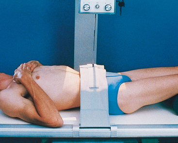
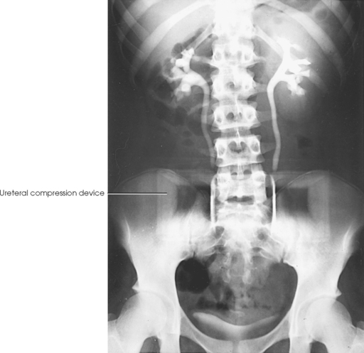
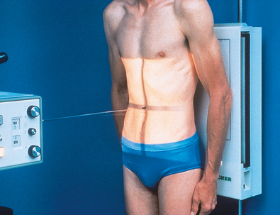
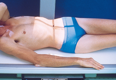
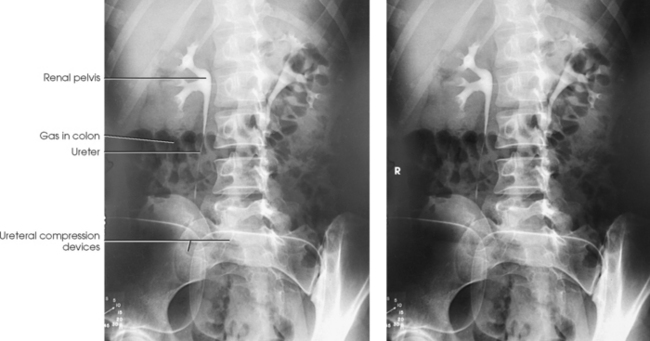
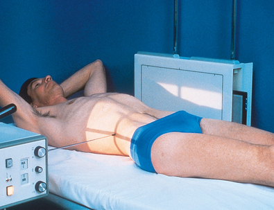
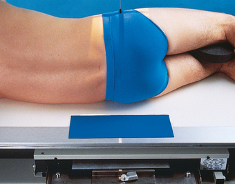
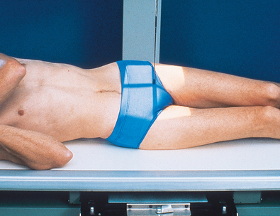
Ureteral compression
In excretory urography, compression is sometimes applied over the distal ends of the ureters. This compression is applied to retard flow of the opacified urine into the bladder and ensure adequate filling of the renal pelves and calyces. If compression is used, it must be placed so that the pressure over the distal ends of the ureters is centered at the level of the anterior superior iliac spine (ASIS). As much pressure as the patient can comfortably tolerate is applied with the immobilization band (Figs. 18-32 and 18-33). The pressure should be released slowly when the compression device is removed to reduce pain caused by rapid change in intraabdominal pressure. Compression is generally contraindicated if a patient has urinary stones, an abdominal mass or aneurysm, a colostomy, a suprapubic catheter, traumatic injury, or recent abdominal surgery.
As a result of improvements in contrast agents, ureteral compression is not routinely used in most health care facilities. With the increased doses of contrast medium now employed, most of the ureteral area is usually shown over a series of radiographs. In addition, a prone radiograph is an adequate substitute to ureteral compression, for filling the pyelocalyceal system and mid-ureters.
Respiration
For the purpose of comparison, all exposures are made at the the same phase of breathing—at the end of expiration unless otherwise requested. Because the normal respiratory excursion of the kidneys varies from ½ to 1½ inches (1.3 to 3.8 cm), it is occasionally possible to differentiate renal shadows from other shadows by making an exposure at a different phase of arrested respiration. When an exposure is made at a respiratory phase different from what is usually used, the image should be so marked.
PRELIMINARY EXAMINATION
A preliminary examination of the abdomen is made before a specialized investigation of the urinary tract is conducted. This examination sometimes reveals extrarenal lesions that are responsible for the symptoms attributed to the urinary tract and renders the urographic procedure unnecessary. An upright AP projection may also be required to show the mobility of the kidneys. An oblique or lateral projection, or both, in the dorsal decubitus position may be required to localize a tumor mass or to differentiate renal stones from gallstones or calcified mesenteric nodes.
The scout radiograph—an AP projection with the patient recumbent—shows the contour of the kidneys; their location in the supine position; and the presence of renal calculi or calcifications outside the renal collecting system, such as phleboliths, which are small calcifications in the wall of pelvic veins (see Fig. 18-31). This radiograph also serves to check the preparation of the gastrointestinal tract and to enable the radiographer to make any necessary alteration in the exposure factors.
Radiation Protection
It is the responsibility of the radiographer to observe the following guidelines concerning radiation protection:
• Apply a gonadal shield if it does not overlap the area under investigation.
• Restrict radiation to the area of interest by close collimation.
• Work carefully so that repeat exposures are unnecessary.
• Shield males for all examinations except examinations of the urethra by using a shadow shield or by placing a piece of lead just below the pubic symphysis.
• When excretory urography IRs are centered to the kidneys, place lead over the female pelvis for shielding. Unless the procedure is considered an emergency, perform radiography of the abdomen and pelvis only if there is no chance of patient pregnancy. For most projections in this chapter, females generally cannot be shielded without obscuring a portion of the urinary system. (Gonad shielding is not shown on the patient radiographs in this atlas for illustrative purposes.) Carefully follow department guidelines regarding gonad shielding.
Intravenous Urography
IVU shows the function and structure of the urinary system. Function is shown by the ability of the kidneys to filter contrast medium from the blood and concentrate it with the urine. Anatomic structures are usually visualized as the contrast material follows the excretion route of the urine.
Indications for IVU include the following:
• Evaluation of abdominal masses, renal cysts, and renal tumors
• Urolithiasis—calculi or stones of the kidneys or urinary tract
• Pyelonephritis—infection of the upper urinary tract, which can be acute or chronic
• Hydronephrosis—abnormal dilation of the pelvicaliceal system (urography is used to help determine the cause of the dilation)
• Evaluation of the effects of trauma
• Preoperative evaluation of the function, location, size, and shape of the kidneys and ureters
• Renal hypertension (urography is commonly performed to evaluate functional symmetry of the renal collecting systems)
The most common contraindications for IVU relate to (1) the ability of the kidneys to filter contrast medium from the blood and (2) the patient’s allergic history. Some contraindications can be overcome by the use of nonionic contrast agents. Patients with conditions in which the kidneys are unable to filter waste or excrete urine (renal failure, anuria) should have the kidneys evaluated by some technique other than excretory urography. Older patients or patients with any of the following risk factors are strong candidates to receive a nonionic contrast medium or should be examined using another modality: asthma, previous contrast media reaction, circulatory or cardiovascular disease, elevated creatinine level, sickle cell disease, diabetes mellitus, or multiple myeloma.
RADIOGRAPHIC PROCEDURE
Before the procedure begins, the patient should be instructed to empty the bladder and change into an appropriate radiolucent gown. Emptying the bladder prevents dilution of the contrast medium with urine. The patient’s clinical history, allergic history, and blood creatinine levels should be reviewed. The normal creatinine level is 0.6 to 1.2 mg/100 mL. The glomerular filtration rate (GFR), a calculation using the creatinine level (plus age, race, gender, and body size), is the best overall index of kidney function. The National Kidney Foundation considers a normal GFR range to be 120 to 125 mL/min and a value of 90 mL/min or less as an indicator of renal dysfunction. A below-normal GFR should be reviewed by the radiologist or the physician before the contrast media procedure is continued. The radiographer then takes the following steps:
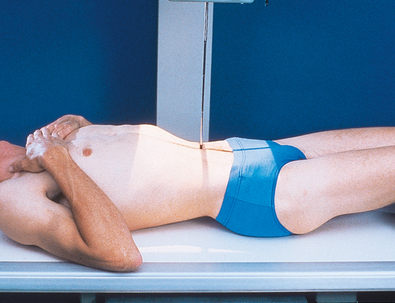
• Place the patient on the table in the supine position, and adjust the patient to center the midsagittal plane of the body to the midline of the grid.
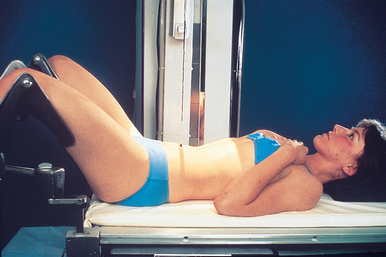
• Place a support under the patient’s knees to reduce the lordotic curvature of the lumbar spine and to provide more comfort for the patient (Fig. 18-34).
• Attach the footboard in preparation for a possible upright or semiupright position.
• If the head of the table is to be lowered farther to enhance pelvicaliceal filling, attach the shoulder support and adjust it to the patient’s height.
• When ureteric compression is to be used, place the compression device so that it is ready for immediate application at the specified time.
• Obtain a preliminary, or scout, radiograph of the abdomen. Then prepare for the first postinjection exposure before the contrast medium is injected.
• Place the IR in the Bucky tray; position the identification, side, and time interval markers; and make any change in centering or exposure technique as indicated by the scout radiograph.
• Have ready a folded towel or other suitable support and the tourniquet for placement under the selected elbow.
• Prepare the contrast medium for injection using aseptic technique.
• According to the preference of the examining physician, administer 30 to 100 mL of the contrast medium to an adult patient of average size. The dose administered to infants and children is regulated according to age and weight.
• Produce radiographs at specified intervals from the time of the completion of the injection of contrast medium. (This may depend on the protocol of the department.) These time intervals must be included on each radiograph. Depending on the patient’s hydration status and the speed of the injection, the contrast agent normally begins to appear in the pelvicaliceal system within 2 to 8 minutes.
The uptake of contrast medium is seen in the nephrons of the kidney if a radiograph is exposed as the kidneys start to filter the contrast medium from the blood. The initial contrast “blush” of the kidney is termed the nephrogram phase. Nephrotomography, if a component of the routine IVU procedure, is usually performed during the nephrogram phase. As the kidneys continue to filter and concentrate the contrast medium, it is directed to the pelvicaliceal system. The greatest concentration of contrast medium in the kidneys normally occurs 15 to 20 minutes after injection. Immediately after each IR is exposed, it is processed and reviewed to determine, according to the kidney function of the individual patient, the time intervals at which the most intense kidney image can be obtained.
The most commonly recommended radiographs for IVU are AP projections at time intervals ranging from 3 to 20 minutes (Figs. 18-35 to 18-37). Some physicians prefer bolus injection of the contrast medium followed by a 30-second image to obtain a nephrogram. AP oblique projections (30-degree) may be taken at 5- to 10-minute intervals. In some patients, supplemental radiographs are required to show better all parts of the urinary system and to differentiate normal anatomy from pathologic conditions. These may include an AP projection with the patient in the Trendelenburg or upright position, oblique or lateral projections, or a lateral projection with the patient in the dorsal or ventral decubitus position.
Unless further study of the bladder is indicated or voiding urethrograms are to be made, the patient is sent to the lavatory to void. A postvoid radiograph of the bladder (Figs. 18-38 and 18-39) may be taken to detect, by the presence of residual urine, conditions such as small tumor masses or enlargement of the prostate gland in men. When all the necessary radiographs have been obtained, the patient is released from the imaging department. Any contrast medium remaining in the body is filtered from the blood by the kidneys and eventually excreted in the urine. Some physicians suggest having the patient drink extra fluids for a few days to help flush out the contrast medium.
 AP PROJECTION
• Place the patient supine on the radiographic table for the AP projection of the urinary system. Preliminary (scout) and postinjection radiographs are most commonly obtained with the patient supine (Fig. 18-40).
• Place a support under the patient’s knees to relieve strain on the back.
• Place the patient in an upright or a semiupright position for an AP projection to show the opacified bladder and the mobility of the kidneys (Fig. 18-41).
• To show the lower ends of the ureters, it may be helpful to use the Trendelenburg position and an AP projection with the head of the table lowered 15 to 20 degrees and the central ray directed perpendicular to the IR. In this angled position, the weight of the contained fluid stretches the bladder fundus superiorly, providing an unobstructed image of the lower ureters and the vesicoureteral orifice areas.
• If needed, apply ureteral compression (see p. 202).
• Center the midsagittal plane of the patient’s body to the midline of the grid device.
• Place the patient’s arms where they do not cast shadows on the IR.
• Center the IR at the level of the iliac crests. If the patient is too tall to include the entire urinary system, take a second exposure on a 10- × 12-inch (24- × 30-cm) IR centered to the bladder. The 10- × 12-inch (24- × 30-cm) IR is placed crosswise and centered 2 to 3 inches (5 to 7.6 cm) above the upper border of the pubic symphysis.
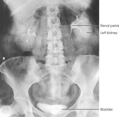
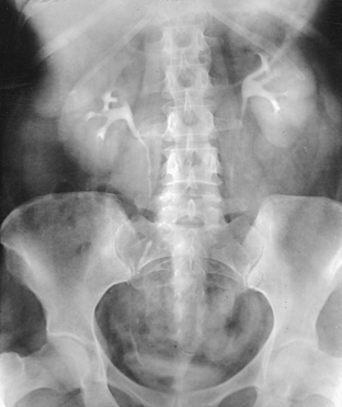
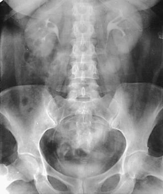
Structures shown: AP projection of the urinary system shows the kidneys, ureters, and bladder filled with the contrast medium (Figs. 18-42 to 18-44).
NOTE: The prone position may be recommended to show the ureteropelvic region and to fill the obstructed ureter in the presence of hydronephrosis. The ureters fill better in the prone position, which reverses the curve of their inferior course. The kidneys are situated obliquely, slanting anteriorly in the transverse plane, so the opacified urine tends to collect in and distend the dependent part of the pelvicaliceal system. The supine position allows the more posteriorly placed upper calyces to fill more readily, and the anterior and inferior parts of the pelvicaliceal system fill more easily in the prone position.
The following should be clearly shown:
 Bladder and pubic symphysis (a separate radiograph of the bladder area is needed if the bladder was not included)
Short scale of radiographic contrast clearly showing contrast medium in the renal area, ureters, and bladder
Compression devices, if used, centered over the upper sacrum and resulting in good renal filling
Vertebral column centered on the radiograph
No artifacts from elastic in the patient’s underclothing
Prostatic region inferior to the pubic symphysis on older male patients
PA projection showing the lower kidneys and entire ureters (bladder included if patient size permits)
Superimposing intestinal gas in the AP projection moved for the PA projection
AP OBLIQUE PROJECTION
• Place the patient supine on the radiographic table for oblique projections of the urinary system. The kidneys are situated obliquely, slanting anteriorly in the transverse plane.
• When performing AP oblique projections, remember that the kidney closer to the IR is perpendicular to the plane of the IR and the kidney farther from the IR is parallel with this plane.
• Turn the patient so that the midcoronal plane forms an angle of 30 degrees from the IR plane.
• Adjust the patient’s shoulders and hips so that they are in the same plane, and place suitable supports under the elevated side as needed.
• Place the arms so that they are not superimposed on the urinary system.
• Center the spine to the grid (Fig. 18-45).
Structures shown: An AP oblique projection of the urinary system shows the kidneys, ureters, and bladder filled with contrast medium. The elevated kidney is parallel with the IR, and the downside kidney is perpendicular with the IR (Fig. 18-46).
LATERAL PROJECTION
• Flex the patient’s knees to a comfortable position, and adjust the body so that the midcoronal plane is centered to the midline of the grid.
• Place supports between the patient’s knees and ankles.
• Flex the patient’s elbows, and place the hands under the patient’s head (Fig. 18-47).
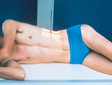
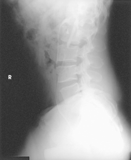
Structures shown: A lateral projection of the abdomen shows the kidneys, ureters, and bladder filled with contrast material. Lateral projections are used to show conditions such as rotation or pressure displacement of a kidney and to localize calcareous areas and tumor masses (Fig. 18-48).
LATERAL PROJECTION
• Place the patient in the supine position on a radiographic cart with the side in question in contact with the vertical grid device. Ensure that the wheels are locked.
• Place the patient’s arms across the upper chest to ensure that they are not projected over any abdominal contents, or place them behind the head.
• Flex the patient’s knees slightly to relieve strain on the back.
• Adjust the height of the vertical grid device so that the long axis of the IR is centered to the midcoronal plane of the patient’s body.
• Position the patient so that a point approximately at the level of the iliac crests is centered to the IR (Fig. 18-49).
• Adjust the patient to ensure no rotation from the supine or prone position is present.
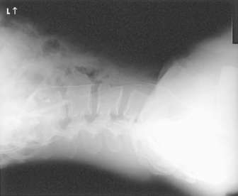
Structures shown: Rolleston and Reay1 recommended the ventral decubitus position to show the UPJ in the presence of hydronephrosis. Cook et al.2 advocated this position to determine whether an extrarenal mass in the flank is intraperitoneal or extraperitoneal, and they stated that the position makes it easy to screen kidneys and ureters for abnormal anterior displacement (Fig. 18-50).
Nephrotomography
The renal parenchyma (nephrons and collecting tubes) is best visualized by performing tomography immediately after the introduction of contrast medium. Evans et al.,1,2 who introduced nephrotomography, found that by using tomography rather than stationary projections they could eliminate superimpositions of intestinal contents and more clearly define small intrarenal lesions.
Indications and contraindications
Nephrotomography is primarily performed to evaluate renal hypertension. It is also useful in delineating renal cysts and renal tumors. Contraindications are mainly related to renal failure and contrast media sensitivity, as noted for IVU.
Examination procedure
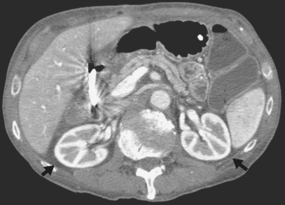
After contrast medium has been injected for IVU, the first AP projection of the abdomen is performed during the arterial phase of opacification (Fig. 18-51), and multiple tomograms of the upper abdomen are obtained during the nephrographic phase after the renal parenchyma becomes opacified—hence the term nephrotomography (Fig. 18-52). The nephrotic phase normally occurs within 5 minutes after completion of the injection or infusion.
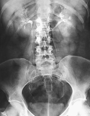
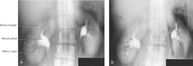
Fig. 18-52 Nephrotomogram: A and B, AP projection at level of 9 cm (A) and 10 cm (B) in the same patient as in Fig. 18-51.
PERCUTANEOUS RENAL PUNCTURE
Percutaneous renal puncture, introduced by Lindblom,1,2 is a radiologic procedure for the investigation of renal masses. Specifically, it is used to differentiate cysts and tumors of the renal parenchyma. This procedure is performed by direct injection of a contrast medium into the cyst under fluoroscopic control (Figs. 18-53 and 18-54). Ultrasonography of the kidney has practically eliminated the need for percutaneous renal puncture. Most masses that are clearly diagnosed as cystic by ultrasound examination are not surgically managed.
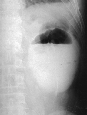
Fig. 18-53 Upright AP left kidney: percutaneous injection of iodinated contrast material and gas into renal cyst.
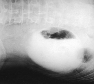
Fig. 18-54 AP projection left kidney, left lateral decubitus position, in the same patient as in Fig. 18-53.
In a similar procedure, the renal pelvis is entered percutaneously for direct contrast filling of the pelvicaliceal system in selected patients with hydronephrosis.1 23 This procedure, called percutaneous antegrade pyelography3 to distinguish it from the retrograde technique of direct pelvicaliceal filling, is usually restricted to the investigation of patients with marked hydronephrosis and patients with suspected hydronephrosis for which conclusive information is not gained by excretory or retrograde urography (Fig. 18-55). This procedure may also be called a nephrostogram because the contrast media injection is frequently made through a percutaneous nephrostomy catheter. Normally, AP abdominal radiographs are obtained for this procedure, although other projections may be requested.
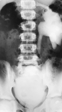
Fig. 18-55 AP projection left kidney, left lateral decubitus position, in the same patient as in Fig. 18-53.
Retrograde Urography
Retrograde urography requires that the ureters be catheterized so that a contrast agent can be injected directly into the pelvicaliceal system. This technique provides improved opacification of the renal collecting system but little physiologic information about the urinary system.
Indications and contraindications
Retrograde urography is indicated for evaluation of the collecting system in patients who have renal insufficiency or who are allergic to iodinated contrast media. Because the contrast medium is not introduced into the circulatory system, the incidence of reactions is reduced.
Examination procedure
Similar to all examinations requiring instrumentation, retrograde urography is classified as an operative procedure. This combined urologic-radiologic examination is performed under careful aseptic conditions by the attending urologist with the assistance of a nurse and radiographer. The procedure is performed in a specially equipped cystoscopic-radiographic examining room that, because of its collaborative nature, may be located in the urology department or the radiology department. A nurse is responsible for the preparation of the instruments and the care and draping of the patient. A responsibility of the radiographer is to ensure that the overhead parts of the radiographic equipment are free of dust for the protection of the operative field and the sterile layout.
The radiographer positions the patient on the cystoscopic table with knees flexed over the stirrups of the adjustable leg supports (Fig. 18-56). This is a modified lithotomy position; the true lithotomy position requires acute flexion of the hips and knees.
If a general anesthetic is not used, the radiographer explains the breathing procedure to the patient and checks the patient’s position on the table. The kidneys and the full extent of the ureters in patients of average height are included on a 14- × 17-inch (35- × 43-cm) IR when the third lumbar vertebra is centered to the grid.
If elevation of the thighs does not reduce the lumbar curve, a pillow is adjusted under the patient’s head and shoulders so that the back is in contact with the table. Most cystoscopic-radiographic tables are equipped with an adjustable leg rest to permit extension of the patient’s legs for certain radiographic studies.
The urologist performs catheterization of the ureters through a ureterocystoscope, which is a cystoscope with an arrangement that aids insertion of the catheters into the vesicoureteral orifices. After the endoscopic examination, the urologist passes a ureteral catheter well into one or both ureters (Fig. 18-57) and, leaving the catheters in position, usually withdraws the cystoscope.
After taking two catheterized specimens of urine from each kidney for laboratory tests—one specimen for culture and one for microscopic examination—the urologist tests kidney function. For this test, a color dye is injected intravenously, and the function of each kidney is determined by the specified time required for the dye substance to appear in the urine as it trickles through the respective catheters.
Immediately after the kidney function test, the radiographer rechecks the position of the patient and exposes the preliminary IR (if this has not been done previously) so that the radiographs are ready for inspection by the time the kidney function test has been completed. After reviewing the image, the urologist injects the contrast medium and proceeds with the urographic examination. When a bilateral examination is to be performed, both sides are filled simultaneously to avoid subjecting the patient to unnecessary radiation exposure. Additional studies in which only one side is refilled may be made as indicated.
The most commonly used retrograde urographic series usually consists of three AP projections: the preliminary radiograph showing the ureteral catheters in position (see Fig. 18-57), the pyelogram, and the ureterogram. Some urologists recommend that the head of the table be lowered 10 to 15 degrees for the pyelogram to prevent the contrast solution from escaping into the ureters. Other urologists recommend that pressure be maintained on the syringe during the pyelographic exposure to ensure complete filling of the pelvicaliceal system. The head of the table may be elevated 35 to 40 degrees for the ureterogram to show any tortuosity of the ureters and the mobility of the kidneys.
Filling of the average normal renal pelvis requires 3 to 5 mL of contrast solution; however, a larger quantity is required when the structure is dilated. The best index of complete filling, and the one most commonly used, is an indication from the patient as soon as a sense of fullness is felt in the back.
When both sides are to be filled, the urologist injects the contrast solution through the catheters in an amount sufficient to fill the renal pelves and calyces. When signaled by the physician, the patient suspends respiration at the expiration, and the exposure for the pyelogram is made (Fig. 18-58).
After the pyelographic exposure, the IR is quickly changed, and the head of the table may be elevated in preparation for the ureterogram. For this exposure, the patient is instructed to inspire deeply and then to suspend respiration at the full expiration. Simultaneously with the breathing procedure, the catheters are slowly withdrawn to the lower ends of the ureters as the contrast solution is injected into the canals. At a signal from the urologist, the ureterographic exposure is made (Fig. 18-59).
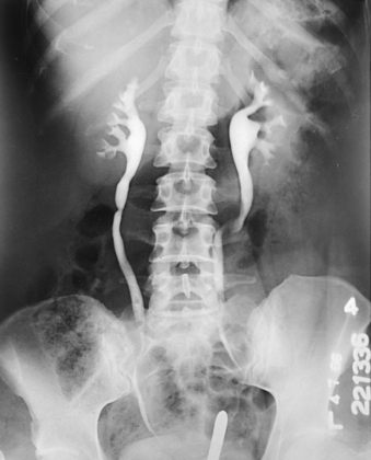
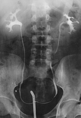
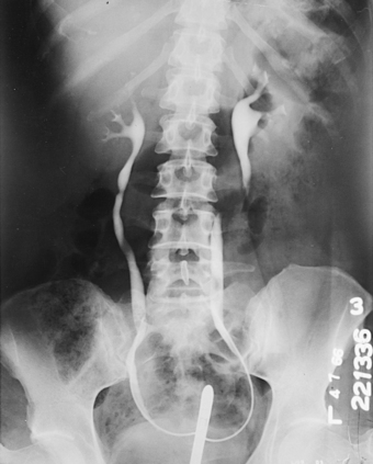
Fig. 18-59 Retrograde urogram showing renal pelves and contrast medium–filled ureters: AP projection.
Additional projections are sometimes required. RPO or LPO (AP oblique) projections are often necessary. Occasionally, a lateral projection, with the patient turned onto the affected side, is performed to show anterior displacement of a kidney or ureter and to delineate a perinephric abscess. Lateral projections with the patient in the ventral or dorsal decubitus position (as required) are also useful, showing the ureteropelvic region in patients with hydronephrosis.
Urinary Bladder, Lower Ureters, Urethra, and Prostate
With few exceptions, radiologic examinations of the lower urinary tract are performed with the retrograde technique of introducing contrast material. These examinations are identified, according to the specific purpose of the investigation, by the terms cystography, cystoureterography, cystourethrography, and prostatography. Most often, they are denoted by the general term cystography. Cystoscopy is not required before retrograde contrast filling of the lower urinary canals, but when both examinations are indicated, they are usually performed in a single-stage procedure to spare the patient preparation and instrumentation for separate examinations. When cystoscopy is not indicated, these examinations are best carried out on an all-purpose radiographic table unless the combination table is equipped with an extensible leg rest.
Indications and contraindications
Retrograde studies of the lower urinary tract are indicated for vesicoureteral reflux, recurrent lower urinary tract infection, neurogenic bladder, bladder trauma, lower urinary tract fistulae, urethral stricture, and posterior urethral valves. Contraindications to lower urinary tract studies are related to catheterization of the urethra.
Contrast media
The contrast agents used for contrast studies of the lower urinary tracts are ionic solutions of either sodium or meglumine diatrizoates or the newer nonionic contrast media mentioned previously. These are the same organic compounds used for IVU, but their concentration is reduced, usually to 30%, for retrograde urography.
Injection equipment
Examinations are performed under careful aseptic conditions. Infants, children, and, usually, adults may be catheterized before they are brought to the radiology department. When the patient is to be catheterized in the radiology department, a sterile catheterization tray must be set up to specifications. Because of the danger of contamination in transferring a sterile liquid from one container to another, the use of commercially available premixed contrast solutions is recommended.
Preliminary preparations
The following guidelines are observed in preparing the patient for the examination:
• Protect the examination table from urine soilage with radiolucent plastic sheeting and disposable underpadding. Correctly arranged disposable padding does much to reduce soilage during voiding studies and consequently eliminates the need for extensive cleaning between patients. A suitable disposal receptacle should be available.
• A few minutes before the examination, accompany the patient to a lavatory. Give the patient supplies for perineal care, and instruct the patient to empty the bladder.
• When the patient is prepared, place the patient on the examination table for the catheterization procedure.
Patients are usually tense, primarily because of embarrassment. It is important that they be given as much privacy as possible. Only the required personnel should be present during the examination, and patients should be properly draped and covered according to room temperature.
Contrast injection
For retrograde cystography (Figs. 18-60 and 18-61), cystourethrography, and voiding cystourethrography, the contrast material is introduced into the bladder by injection or infusion through a catheter passed into position via the urethral canal. A small, disposable Foley catheter is used to occlude the vesicourethral orifice in the examination of infants and children, and this catheter may be used in the examination of adults when interval studies are to be made for the detection of delayed ureteral reflux.
Studies are made during voiding to delineate the urethral canal and to detect ureteral reflux, which may occur only during urination (Fig. 18-62). When urethral studies are to be made during injection of contrast material, a soft rubber urethral-orifice acorn is fitted directly onto a contrast-loaded syringe for female patients and is usually fitted onto a cannula attached to a clamp device for male patients.
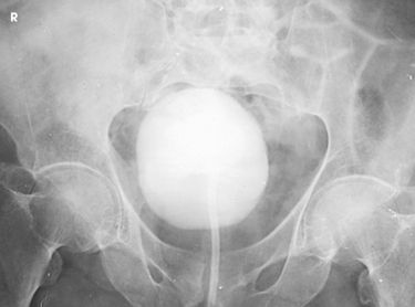
RETROGRADE CYSTOGRAPHY
In preparing for this examination, the following steps are taken:
• With the urethral catheter in place, adjust the patient in the supine position for a preliminary radiograph and the first cystogram.
• Usually, take cystograms of adult patients on 10- × 12-inch (24- × 30-cm) IRs placed lengthwise.
• Center the IR at the level of the soft tissue depression just above the most prominent point of the greater trochanters. This centering coincides with the middle area of a filled bladder of average size. The 12-inch (30-cm) IR includes the region of the distal the ureters to show ureteral reflux and the prostate and proximal part of the male urethra.
• Have large IRs nearby for use when ureteral reflux is shown. Some radiologists request studies during contrast filling of the bladder and during voiding.
After the preliminary radiograph is taken, the physician removes the catheter clamp, and the bladder is drained in preparation for the introduction of the contrast material. After introducing the contrast agent, the physician clamps the catheter and tapes it to the thigh to keep it from being displaced during position changes.
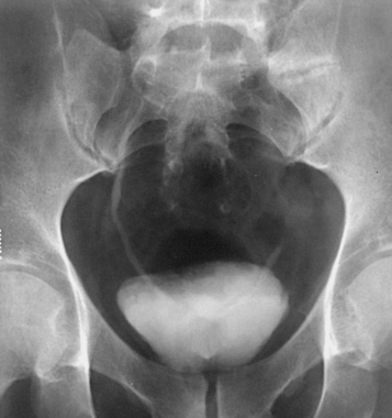
The initial cystographic images generally consist of four projections: one AP, two AP obliques, and one lateral. Additional studies, including voiding cystourethrograms, are obtained as indicated. The Chassard-Lapiné method (see Chapter 7, Volume 1), often called the “squat shot,” is sometimes used to obtain an axial projection of the posterior surface of the bladder and the lower the ureters when they are opacified. These projections of the bladder are also made when it is opacified by the excretory technique of urography.
Urinary Bladder
AP AXIAL OR PA AXIAL PROJECTION
NOTE: Preliminary (scout) and postinjection radiographs are most commonly obtained with the patient supine. The prone position is sometimes used to image areas of the bladder not clearly seen on the AP axial projection. An AP axial projection using the Trendelenburg position at 15 to 20 degrees and with the central ray directed vertically is sometimes used to show the distal ends of the ureters. In this angled position, the weight of the contained fluid stretches the bladder fundus superiorly, giving an unobstructed projection of the lower ureters and the vesicoureteral orifice areas.
• Center the midsagittal plane of the patient’s body to the midline of the grid device.
• Adjust the patient’s shoulders and hips so that they are equidistant from the IR.
• Place the patient’s arms where they do not cast shadows on the IR.
• If the patient is positioned for a supine radiograph, have the patient’s legs extended so that the lumbosacral area of the spine is arched enough to tilt the anterior pelvic bones inferiorly. In this position, the pubic bones can more easily be projected below the bladder neck and proximal urethra (Fig. 18-63).
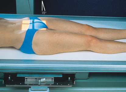
• Center the IR 2 inches (5 cm) above the upper border of the pubic symphysis (or at the pubic symphysis for voiding studies).
• Angled 10 to 15 degrees caudal to the center of the IR. The central ray should enter 2 inches (5 cm) above the upper border of the pubic symphysis. When the bladder neck and proximal urethra are the main areas of interest, a 5-degree caudal angulation of the central ray is usually sufficient to project the pubic bones below them. More or less angulation may be necessary, depending on the amount of lordosis of the lumbar spine. With greater lordosis, less angulation may be needed (see Fig. 18-63).
• When performing PA axial projections of the bladder, direct the central ray through the region of the bladder neck at an angle of 10 to 15 degrees cephalad, entering about 1 inch (2.5 cm) distal to the tip of the coccyx and exiting a little above the superior border of the pubic symphysis. If the prostate is the area of interest, the central ray is directed 20 to 25 degrees cephalad to project it above the pubic bones. For PA axial projections, the IR is centered to the central ray.
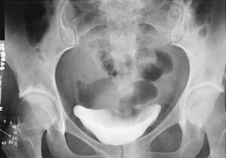
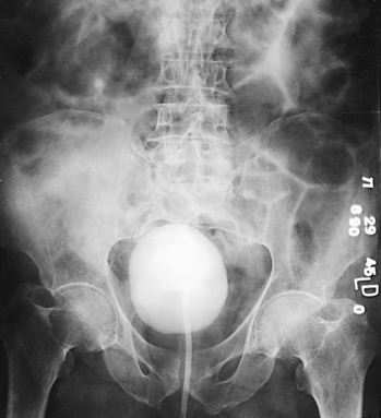
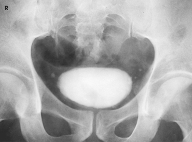
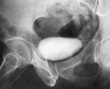
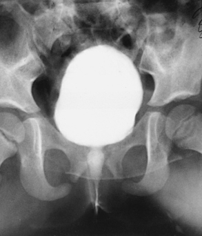
Structures shown: AP axial and PA axial projections show the bladder filled with contrast medium (Figs. 18-64 and 18-65). If reflux is present, the distal ureters are also visualized.
AP OBLIQUE PROJECTION
• Rotate the patient 40 to 60 degrees RPO or LPO, according to the preference of the examining physician (Fig. 18-66).
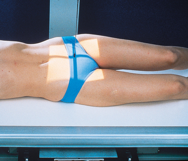
• Adjust the patient so that the pubic arch closest to the table is aligned over the midline of the grid.
• Extend and abduct the uppermost thigh enough to prevent its superimposition on the bladder area.
• Center the IR 2 inches (5 cm) above the upper border of the pubic symphysis and approximately 2 inches (5 cm) medial to the upper ASIS (or at the pubic symphysis for voiding studies).
• Perpendicular to the center of the IR. The central ray falls 2 inches (5 cm) above the upper border of the pubic symphysis and 2 inches (5 cm) medial to the upper ASIS. When the bladder neck and proximal urethra are the main areas of interest, a 10-degree caudal angulation of the central ray is usually sufficient to project the pubic bones below them.
• Perpendicular at the level of the pubic symphysis for voiding studies
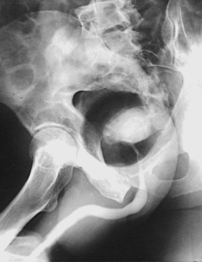
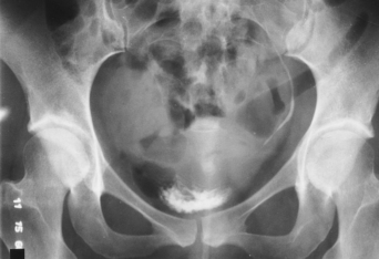
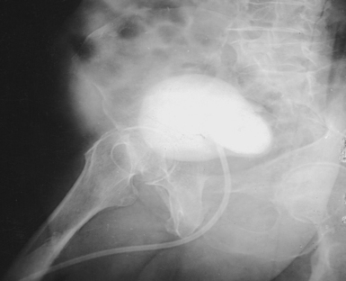
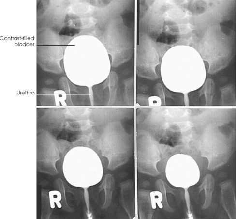
Structures shown: Oblique projections show the bladder filled with contrast medium. If reflux is present, the distal ureters are also visualized (Figs. 18-67 and 18-68).
LATERAL PROJECTION
Image receptor: 10 × 12 inch (24 × 30 cm) lengthwise
• Slightly flex the patient’s knees to a comfortable position, and adjust the body so that the midcoronal plane is centered to the midline of the grid.
• Flex the patient’s elbows, and place the hands under the head (Fig. 18-69).
• Center the IR 2 inches (5 cm) above the upper border of the pubic symphysis at the midcoronal plane.
Structures shown: A lateral image shows the bladder filled with the contrast medium. If reflux is present, the distal ureters are also visualized. Lateral projections shows the anterior and posterior bladder walls and the base of the bladder (Fig. 18-70).
Male Cystourethrography
RPO or LPO position
Male cystourethrography may be preceded by an endoscopic examination, after which the bladder is catheterized so that it can be drained just before contrast material is injected.
The following steps are taken:
• Use 10- × 12-inch (24- × 30-cm) IRs placed lengthwise for cystourethrograms in men.
• The patient is adjusted on the combination table so that the IR can be centered at the level of the superior border of the pubic symphysis. This centering coincides with the root of the penis, and a 12-inch (30-cm) IR includes the bladder and the external urethral orifice.
• After inspecting the preliminary radiograph, the physician drains the bladder and withdraws the catheter.
• The supine patient is adjusted in an oblique position so that the bladder neck and the entire urethra are delineated as free of bony superimposition as possible. Rotate the patient’s body 35 to 40 degrees, and adjust it so that the elevated pubis is centered to the midline of the grid. The superimposed pubic and ischial rami of the down side and the body of the elevated pubis usually are projected anterior to the bladder neck, proximal urethra, and prostate (Fig. 18-71).
• The patient’s lower knee is flexed only slightly to keep the soft tissues on the medial side of the thigh as near to the center of the IR as possible.
• The elevated thigh is extended and retracted enough to prevent overlapping.
• With the patient in the correct position, the physician inserts the contrast medium–loaded urethral syringe or the nozzle of a device such as the Brodney clamp into the urethral orifice. The physician extends the penis along the soft tissues of the medial side of the lower thigh to obtain a uniform density of the deep and the cavernous portions of the urethral canal.
• At a signal from the physician, instruct the patient to hold still; make the exposure while the injection of the contrast material is continued to ensure filling of the entire urethra (Fig. 18-72).
• The bladder may be filled with a contrast material so that a voiding study can be performed (Fig. 18-73). This is usually done without changing the patient’s position. When a standing-upright voiding study is required, the patient is adjusted before a vertical grid device and is supplied with a urinal. (Further information on positioning is provided on pp. 218-222 of this volume.)
Female Cystourethrography
The female urethra averages 1½ inches (3.5 cm) in length. Its opening into the bladder is situated at the level of the superior border of the pubic symphysis. From this point, the vessel slants obliquely inferiorly and anteriorly to its termination in the vestibule of the vulva, about 1 inch (2.5 cm) anterior to the vaginal orifice. The female urethra is subject to conditions such as tumors, abscesses, diverticula, dilation, and strictures. It is also subject to urinary incontinence during the stress of increased intraabdominal pressure, such as occurs during sneezing or coughing. In the investigation of abnormalities other than stress incontinence, contrast studies are made during the injection of contrast medium or during voiding.
Cystourethrography is usually preceded by an endoscopic examination. For this reason, it may be performed by the attending urologist or gynecologist with the assistance of a nurse and a radiographer.
The following steps are observed:
• After the physical examination, the cystoscope is removed, and a catheter is inserted into the bladder so that the bladder can be drained just before injection of the contrast solution.
• The patient is adjusted in the supine position on the table.
• An 8- × 10-inch (18- × 24-cm) or 10- × 12-inch (24- × 30-cm) IR is placed lengthwise and centered at the level of the superior border of the pubic symphysis.
• A 5-degree caudal angulation of the central ray is usually sufficient to free the bladder neck of superimposition.
• After inspecting the preliminary radiograph, the physician drains the bladder and withdraws the catheter. The physician uses a syringe fitted with a blunt-nosed, soft rubber acorn, which is held firmly against the urethral orifice to prevent reflux as the contrast solution is injected during the exposure.
• Oblique projections may be required in addition to the AP projection. For oblique projections, the patient is rotated 35 to 40 degrees so that the urethra is posterior to the pubic symphysis. The uppermost thigh is extended and abducted enough to prevent overlapping.
• Further information on positioning is provided on pp. 220 of this volume.
• The physician fills the bladder for each voiding study to be made.
• For an AP projection (Figs. 18-74 and 18-75), the patient is maintained in the supine position, or the head of the table is elevated enough to place the patient in a semiseated position.
• A lateral voiding study of the female vesicourethral canal is performed with the patient recumbent or upright. In either case, the IR is centered at the level of the superior border of the pubic symphysis.
Metallic bead chain cystourethrography
The metallic bead chain technique of investigating anatomic abnormalities responsible for stress incontinence in women was described by Stevens and Smith1 in 1937 and by Barnes2 in 1940. This technique is used to delineate anatomic changes that occur in the shape and position of the bladder floor, in the posterior urethrovesical angle, in the position of the proximal urethral orifice, and in the angle of inclination of the urethral axis under the stress of increased intraabdominal pressure as exerted by the Valsalva maneuver.
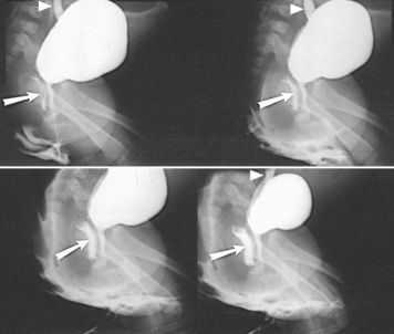
Comparison AP and lateral projections are made with the patient standing at rest (Figs. 18-76 and 18-77) and straining (Figs. 18-78 and 18-79).
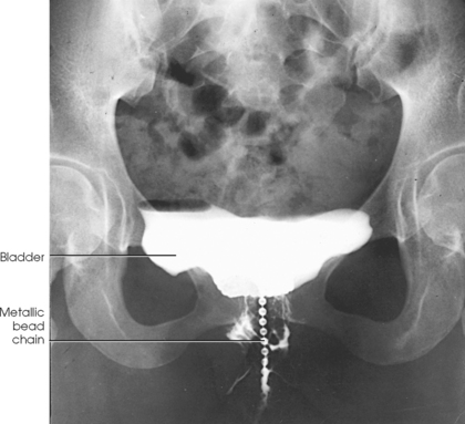
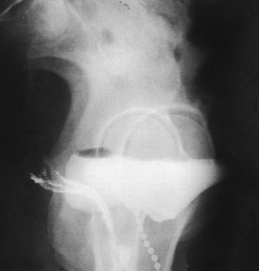
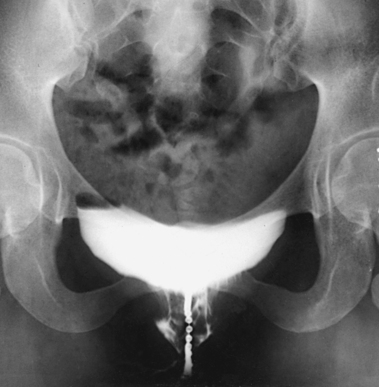
Fig. 18-78 Upright cystourethrogram: stress AP projection in the same patient as in Fig. 18-76.
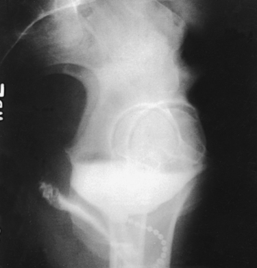
For this examination, the physician extends a flexible metallic bead chain through the urethral canal. The proximal portion of the chain rests within the bladder, and the distal end is taped to the thigh. To show the length of the urethra, a small metal marker is attached with a piece of tape to the vaginal mucosa just lateral to the urethral orifice. After instillation of the metallic chain, a catheter is passed into the bladder, the contents of the bladder are drained, and an opaque contrast solution is injected. The catheter is removed for the imaging procedure.
Hodgkinson et al.1 recommended the upright position, which uses gravity and simulates normal body activity. Two sets of images (AP and lateral projections) are obtained, and the rest of the studies must be exposed before the stress studies are made because the bladder does not immediately return to its normal resting position after straining.
After the metallic chain and contrast solution are instilled, the patient is usually prepared for upright radiographs. The examining room should be readied in advance so that the patient, who will be uncomfortable, can be given immediate attention. The patient must be given kind reassurance and must be examined in privacy. Klawon1 found that the fear of involuntary voiding can be relieved by placing a folded towel or disposable pad between the patient’s thighs before the stress radiographs are taken. Thus protected, the patient willingly applies full pressure during the stress studies.
The IR size and centering point are the same as for other female cystourethrograms. (Further information on positioning of the lower urinary tract is provided on p. 224 of this volume.)
Steven C. Jensen and Eric P. Matthews
Advances in medical science and modern technology are creating tremendous changes and improvements in IV therapy, especially for clinicians who perform diagnostic imaging. As IV therapy has evolved over the years, radiologic technologists are being assigned roles in the patient-focused, cost-effective collaborative team concept of modern health care. An estimated 80% of patients in acute-care settings require some type of IV medication. Administering medications accurately and safely is an important responsibility that must not be taken lightly.1
The principles of IV therapy include restoring and maintaining fluid and electrolyte balance, administering medication, transfusing blood, and delivering parenteral nutrition solutions. Although the need for technologist-performed venipuncture is decreasing, particularly as the number of renal imaging studies declines in the routine diagnostic radiology department, there is still a need for the technologist to be familiar with the techniques required to attain and sustain venous access, particularly as the use of CT increases in diagnosing renal pathologies. The radiologic technologist may initiate venipuncture and administer medications by physician order for specific indications in certain types of IV therapy related to radiographic procedures; commonly, this medication consists of some type of radiographic contrast medium.1
Professional and Legal Considerations
Because of patient risk and legal liabilities, the radiologic technologist must follow professional recommendations, state regulations, and institutional policies for the administration of medications. The information presented in this section is meant to be an introduction to IV therapy. Competency in this area requires the completion of a formal course of instruction with supervised clinical practice and evaluation.
The American Society of Radiologic Technologists (ASRT) includes venipuncture and IV medication administration in the curriculum guidelines for the educational opportunities offered to technologists. Additional support for the administration of medications and venipuncture as part of the technologist’s scope of practice is found in the 1987 Resolution No. 27 from the ACR.1 This resolution supports the injection of contrast materials and diagnostic levels of radiopharmaceuticals within specific established guidelines by certified or licensed radiologic technologists. The ASRT Standards of Practice for Radiography also support the administration of medication by technologists.
Technologists who perform venipuncture and contrast media administration must be knowledgeable about the specific state regulations and facility policies that govern these activities. Technologists also are responsible for professional decisions and actions in their practice. Competency in the skills of venipuncture and contrast media administration are based on cognitive knowledge, proficiency in psychomotor skills, positive affective values, and validation in a clinical setting.
Medications
Medications for a specific procedure are prescribed by a physician, who is also responsible for obtaining informed consent for the procedure. A technologist may administer medications for radiographic procedures, which can require medications for sedation, pain management, contrast media administration, and emergencies.2 The technologist must have an extensive knowledge of all medications used in the radiology department. IV medications are administered into the body via the vascular system; when administered, they cannot be retrieved. Before administering any medication, the technologist must know the medication’s name, dosages, indications, contraindications, and possible adverse reactions (Table 18-1).
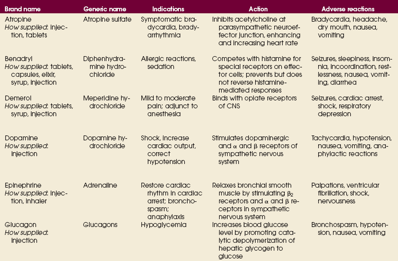

Patient Education
The manner in which the technologist approaches the patient can have a direct influence on the patient’s response to the procedure. Although the technologist may consider the procedure routine, the patient may be totally unfamiliar with its specifics. Apprehension experienced by the patient can cause vasoconstriction, making the venipuncture more difficult and more painful.1 Careful explanation and a confident, sympathetic attitude can help the patient relax.
The technologist must provide information about the procedure in terms the patient can understand. The patient’s questions must be answered in “layman’s” language. By explaining the details of the procedure, the technologist can help alleviate fears and solicit cooperation from the patient. It is important to explain the steps in the procedure, its expected duration, and any limitations or restrictions associated with its performance. The patient may have heard an inaccurate “horror” story about the procedure from a neighbor or friend. The technologist may need to correct misconceptions and provide accurate information.
For simple procedures, the patient must be reassured that the process is relatively straightforward and causes only slight discomfort. For more complex and longer procedures, the technologist must gain the patient’s cooperation by providing appropriate, factual information and offering support. The patient should never be told that insertion of the needle used in venipuncture does not hurt. After all, a foreign object is going to be inserted through the patient’s skin, which has myriad nerves that may be aggravated by insertion of a needle. The technologist must tell the truth and explain that the amount of pain experienced varies with each patient.2
Patient Assessment
The patient must be assessed before any medication is administered. A thorough patient history must be obtained, including any allergies the individual may have. It is essential to determine whether the patient has any known allergies to foods, medications, environmental agents, or other substances. Before venipuncture is performed, the technologist needs to be aware of the potential for an allergic reaction to the iodine tincture used in puncture site preparation or an adverse reaction to the medication being injected.
Other assessment criteria include the patient’s current medications. Knowledge of some common medication actions can help the radiologic technologist evaluate changes in a patient’s condition during a procedure. Certain diabetic medications interact adversely with contrast media. The interaction of medications must be assessed before the performance of the procedure.
During the physical evaluation, it is important to determine whether the patient has previously undergone surgical procedures that might affect site selection for venipuncture (e.g., a mastectomy with resultant compromised lymph nodes and vascular abnormalities, such as atrioventricular shunts). To determine the appropriate type and amount of medication to be administered, the physician requires information about the patient’s past and current disease processes, such as hypertension and renal disease. Evaluation of the blood urea nitrogen (BUN) level (average range 10 to 20 mg/dL) and the creatinine level (average range 0.05 to 1.2 mg/dL) should be included as assessment criteria.
Infection Control
Each time the body system is entered, the potential for contamination exists.1 Strict aseptic techniques and universal precautions must always be used when medications are administered with a needle.2 If a medication is injected incorrectly, a microorganism may enter the body and cause an infection or other complications. The U.S. Centers for Disease Control and Prevention (CDC) have developed specific guidelines to prevent the transmission of infections during the preparation and administration of medications. These guidelines are part of the standard precautions used by every health care facility, and strict adherence to the guidelines must be followed by the technologist during the performance of radiologic procedures.
Studies using IV filters have shown a significant reduction in infusion phlebitis. Filters are devices located within the tubing used for IV administration. Filters prevent the injection of particulate and microbial matter into the circulatory system. The use of a filter for a bolus injection reduces the rate at which the medication can be injected. In addition, the viscosity of a medication may determine whether a filter is used and the rate of injection. Although a filter helps in reducing the possibility of bacteria being introduced into the blood, its use creates additional factors of risks versus benefits. The physician or health care facility should have policies to address these issues.
Venipuncture Supplies and Equipment
The technologist assembles the proper syringe and needle for the planned injection. The syringe may be glass or plastic. Plastic syringes are disposed of after only one use; glass syringes may be cleaned and must be sterilized before they are used again. The syringe has three parts: the tip, where the needle attaches to the syringe; the barrel, which includes the calibration markings; and the plunger, which fits snugly inside the barrel and allows the user to instill the medication (Fig. 18-80). The tip of the syringe for an IV injection has a locking device to hold the needle securely. The size of the syringe depends on the volume of material to be injected. The technologist should select a syringe one size larger than the volume desired. This larger syringe assists in the accuracy of the dose by allowing the total amount of medication to be drawn into one syringe.
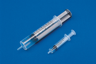
All needles used in venipuncture are disposable and are used only once. During the preparation and administration of contrast media, the technologist may use several types of needles, including a hypodermic needle, a butterfly set, and an overthe-needle cannula (Fig. 18-81).
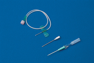
Fig. 18-81 Types of needles: over-the-cannula needle, or angiocatheter (bottom); hypodermic needle (center); and metal butterfly needle (top).
Hypodermic needles vary in gauge and length (see Fig. 18-81). Needle gauge refers to the diameter of the needle bore, with the gauge increasing as the diameter of the bore decreases. An 18-gauge needle is larger than a 22-gauge needle. As the bore of the needle increases, a given volume of fluid may be administered more rapidly. If bore size is reduced and fluid volume and rate of administration remain constant, the pressure (force) of the injection increases. The length of a needle is measured in inches and may range from ½ inch (1.3 cm) (used for intradermal injections) to 4½ inches (11.5 cm) (used for intrathecal [spinal] injections). Generally, needles 1 to 1½ inches (2.5 to 3.8 cm) long are most commonly used for IV injections. The needle has three parts: the hub, which is the part that attaches to the syringe; the cannula or shaft, which is the length of the needle; and the bevel, which is the slanted portion of the needle tip. Needles should be visually examined before and after use to determine whether any structural defects, such as nonbeveled points or bent shafts, are present.1
Butterfly sets or angiocatheters are preferable to a conventional hypodermic needle for most radiographic IV therapies. The butterfly set consists of a stainless-steel needle with plastic appendages on either side and approximately 6 inches of plastic tubing that ends with a connector. The plastic appendages, often called wings, aid in inserting the needle and stabilizing the needle after venous patency has been confirmed.
The over-the-needle cannula is a device in which, after the venipuncture is made, the catheter is slipped off the needle into the vein and the steel needle is removed. This type of needle is recommended for long-term therapy or for rapid infusions, such as infusions that use an automated power injector. The choice of needle should be based on the assessment of the patient, institutional policy, and the technologist’s preference.
MEDICATION PREPARATION
Although IV drug administration offers the most immediate results in terms of effect, certain safety precautions must be followed. The technologist must identify the correct patient before medication is administered. During preparation and again before administration, the medication in the container also must be verified.
If the medication is supplied in a bottle or vial, the preparation procedure has several variations. First, the solution must be evaluated for contamination. Discoloration and dissolution are the most common signs of contamination. If either of those is observed, the solution should not be used. Then the protective cap is removed, with care taken not to contaminate the underlying surface. Containers have rubber stoppers through which a hypodermic needle can be inserted. If a single-dose vial is being used, and no contamination has occurred, the rubber stopper requires no additional cleansing. Multipledose vial stoppers must be cleaned with an alcohol wipe.
For a closed system to be maintained and to reduce the chance of possible infection, a volume of air equal to the amount of desired fluid must be injected into the bottle. The plunger of the syringe is pulled back to the level of the desired amount of medication. The shaft of the plunger must not be contaminated at any time during preparation of the medication. The needle on the syringe is inserted into the rubber stopper, all the way to the hub of the needle. Then the vial is inverted by placing the the needle above the fluid level in the bottle (Fig. 18-82). Next, a small amount of air is slowly injected into the vial above the level of the fluid. This technique helps decrease air bubbles in the solution. After the air has been injected, the vial and syringe are held inverted and perpendicular to a horizontal plane, and the tip of the needle is pulled below the fluid level. The desired amount of medication is aspirated into the syringe by pulling down on the plunger of the syringe. This procedure may have to be repeated several times to expel all of the medication. If air bubbles cling to the syringe casing, the syringe may be lightly tapped to release them. A one-handed method is used to recap the syringe (Fig. 18-83).
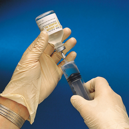
Fig. 18-82 Place tip of needle above level of fluid before injection of air to decrease air bubbles in solution.
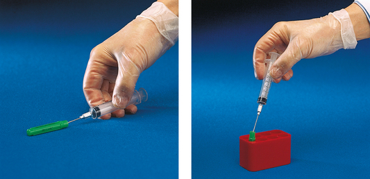
Preparation of an infusion from a glass bottle or plastic bag begins with the identification and verification of the solution and its expiration date (Fig. 18-84). The solution should not contain any visible particles. The tubing used for the infusion is determined by the method of injection and the type of container. Electronic infusion devices require different tubing than gravity infusion devices. A glass container necessitates a vented tubing (Fig. 18-85), whereas a plastic container requires a nonvented tubing (Fig. 18-86).
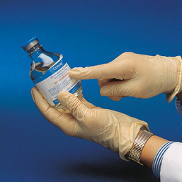
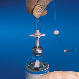
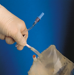
To prepare for drip infusion of a medication, the technologist removes the tubing from the sterile package and closes the clamp (Fig. 18-87). Failure to close the clamp may result in loss of the vacuum in the solution container. The protective coverings are removed from the port of the solution and the tubing spike. Then the fill chamber of the tubing is squeezed, and the spike is inserted into the solution. The solution is then inverted, and the chamber is released. The solution should fill the chamber to the measurement line. The tubing is primed by opening the clamp, which allows the solution to travel the length of the tubing, expelling any air. The tube is filled with solution, the clamp is closed, and the protective covering is secured. The solution is then ready for administration.
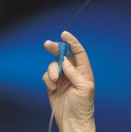
Procedure
Selection of an appropriate vein for venipuncture is crucial. Finding the vein is sometimes difficult, and the most visible veins are not always the best choice.1 Technologists administer IV medication and contrast media via the venous system. If a pulse is palpated during assessment for a puncture site, that vessel must not be used because it is an artery. The prime factors to consider in selecting a vein are (1) suitability of location, (2) condition of the vein, (3) purpose of the infusion, and (4) duration of therapy. The veins most often used in establishing IV access are found on the anterior forearm, posterior hand, radial aspect of the wrist, and antecubital space on the anterior surface of the elbow (Fig. 18-88).
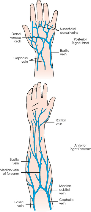
A general rule is to select the most distal site that can accept the desired-size needle and tolerate the injection rate and solution. Although the veins located at the antecubital space may be the most accessible, largest, and easiest to puncture, they may not be the best choice. Because of their convenient location, these sites may be overused and can become scarred or sclerotic. Antecubital accesses are located over an area of joint flexion; any motion can dislodge the cannula and cause infiltration or result in mechanical phlebitis. A flexible IV catheter is the needle of choice for placement of a venous access in the antecubital space. The patient’s arm should be immobilized to inhibit the ability to flex the elbow.
The condition of the vein must also be considered in the selection of an appropriate puncture site. The selected vein must be able to tolerate the needed or desired cannula size. The vein should have resilience qualities and be anchored by surrounding supportive tissues to prevent rolling.
Another consideration in vein selection is the rate of flow required for the procedure and the viscosity and amount of medication to be administered. Because the purpose of the infusion determines the rate of flow, the solution to be infused should be evaluated during the site selection process. Larger veins should be selected for infusions of large quantities or for rapid infusions. Large veins are also used for the infusion of highly viscous solutions or solutions that are irritating to vessels.1
The expected duration of the therapy and the patient’s comfort are other factors that must be considered in selecting a venipuncture site. If a prolonged course of therapy is anticipated, areas over flexion joints should be avoided, and the dorsal surfaces of the upper limbs should be carefully examined. Venous access in these locations provides more freedom and comfort to the patient.
SITE PREPARATION
The surface of the skin must be prepared and cleaned. If the area selected for venipuncture is hairy, the hair should be clipped to permit better cleansing of the skin and visualization of the vein; this also makes removal of the cannula less painful when the infusion is terminated. Shaving is not recommended. The skin is cleansed with an antiseptic, which should remain in contact with the skin for at least 30 seconds. The preferred solution is iodine tincture 1% to 2%. Isopropyl alcohol 70% is recommended if the patient is sensitive to iodine. The skin should be cleaned in a circular motion from the center of the injection site to approximately a 2-inch circle. When the swab has been placed on the skin, it should not be lifted from the surface until the cleansing process is complete (Fig. 18-89).
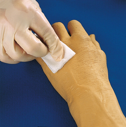
Many facilities have a policy that provides the patient an opportunity to request a local anesthetic for IV infusion catheter placement. This technique reduces the pain felt by the patient during insertion of an angiocatheter or needle. The local anesthetic can be administered topically or by injection.
A facility’s procedure for local anesthetic determines the specific criteria for that institution. Commonly accepted guidelines are as follows: First, 0.1 to 0.2 mL of 1% lidocaine without epinephrine or sterile saline is prepared in a tuberculin or insulin syringe with a 23- to 25-gauge needle. The site for injection is selected and prepared. Then the anesthetic is injected subcutaneously (beneath the skin, into the soft tissue) or intradermally (immediately under the skin in the dermal layer) at the venipuncture site. Topical anesthesia is achieved by applying 5 g of eutectic mixture of local anesthetic cream and covering the area with an occlusive dressing. Maximal effects are achieved in 45 to 60 minutes.
The medication to be injected should already be prepared, and any tubing should be primed with the solution to prevent injection of any air into the vascular system.
VENIPUNCTURE
After the solution has been prepared, the site has been selected, and the type of syringe and needle to be used has been determined, the technologist is ready to perform the venipuncture.
Techniques for venipuncture follow one of two courses: (1) the direct, or one-step, entry method or (2) the indirect method. The direct, or one-step, method is performed by thrusting the cannula through the skin and into the vein in one quick motion. The needle and cannula enter the skin directly over the vein. This technique is excellent as long as large veins are available.1 The indirect method is a two-step technique. First, the over-the-needle cannula is inserted through the skin adjacent to or below the point where the vein is visible. The cannula is advanced and maneuvered to pierce the vein. For the actual venipuncture procedure, the technologist washes the hands. The patient is identified. Next, the technologist instructs the patient about the procedure. The technologist performs the following steps:
1. The technologist puts on gloves and cleans the area in accordance with facility protocol (Fig. 18-90).
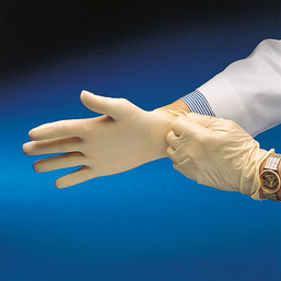
2. A local anesthetic is administered according to facility policy (optional).
3. A tourniquet is placed 6 to 8 inches (15 to 20 cm) above the intended site of puncture. The tourniquet should be tight enough to distend the vessels but not occlude them. The loose ends of the tourniquet should be placed away from the injection site to prevent contamination of the aseptic area (Fig. 18-91).
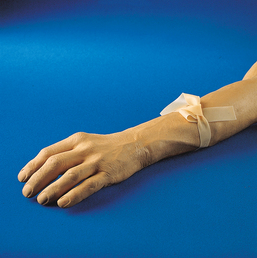
Fig. 18-91 Apply tourniquet 6 to 8 inches above intended venipuncture site, with free end directed superiorly.
4. The technologist holds the patient’s limb with the nondominant hand, using that thumb to stabilize and anchor the selected vein. The best method of accessing the vein—direct or indirect technique—is determined.
5. Using the dominant hand, the technologist places the needle bevel up at a 45-degree angle to the skin’s surface. The bevel-up position produces less trauma to the skin and vein (Fig. 18-92).
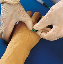
6. The technologist uses a quick, sharp darting motion to enter the skin with the needle. On entering the skin, the technologist decreases the angle of the needle to 15 degrees from the long axis of the vessel. Using an indirect method, the technologist slowly proceeds with a downward motion on the hub or wings of the needle; raising the point of the needle, the technologist advances the needle parallel and then punctures the vein. The needle may have to be maneuvered slightly to facilitate actual venous puncture. If the direct method of access is used, the needle is placed on the skin directly over the vein, and entry into the vein is accomplished in one movement of the needle through the skin and vein. When the vein is entered, a backflow of blood may occur—this indicates a successful venipuncture.
7. After the vein is punctured and a blood return is noted, the cannula is advanced cautiously up the lumen of the vessel for approximately ¾ inch (1.9 cm).
8. Release the tourniquet (Fig. 18-93).
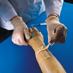
Fig. 18-93 Release tourniquet after venous access has been obtained. Do not permit tourniquet to touch needle.
9. If a backflow of blood does not occur, verify venous access before injecting the medication. Aspiration of blood directly into the syringe of medication verifies placement before injecting. Another method of placement verification is to attach a syringe of normal saline to the hub of the needle before aspirating for blood. The advantage of this method is that only saline, an isotonic solution, is injected if the needle is not in place and extravasation occurs. A successful venipuncture does not guarantee a successful injection. If a bolus injection is desired, the tourniquet may not be released until the injection has been completed. If this technique is used, the protocol must be included in the facility’s policies and procedures.
10. Anchor the needle with tape and a dressing, as required by policy (Fig. 18-94). Then administer the medication (Fig. 18-95).
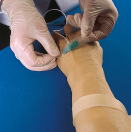
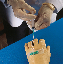
With experience, a technologist’s fingers become sensitive to the sensation of the needle entering the vein—the resistance encountered as the needle penetrates the wall of the vein and the “pop” felt at the loss of resistance as the cannula enters the lumen. If both walls of the vein are punctured with a needle, the vessel develops a hematoma. The cannula should be removed immediately, and direct pressure should be applied to the puncture site. If a venipuncture attempt is unsuccessful with an over-the-needle cannula and the needle has been removed from the cannula, the needle should not be reinserted into the catheter. Reinserting the needle into the cannula can shear a portion of the catheter.
ADMINISTRATION
The technologist should administer the medication or contrast medium at the established rate. During the injection process, the injection site should be observed and palpated proximal to the puncture for signs of infiltration. An infiltration, or extravasation, is a process whereby a fluid passes into the tissue instead of the vein.
A patient may have a venous access that was established before the radiologic procedure. A careful assessment of site and medication compatibility must be performed before the existing IV line can be used. (Compatibility is the ability of one medication to mix with another.) Special precautions should be taken with a patient who is currently receiving cardiac, blood pressure, heparin, or diabetes medications. The physician, nurse, or pharmacist should be consulted before medication is administered to such a patient. Verification must be obtained to ensure that the medication being infused through the established IV line is compatible with the contrast medium to be administered. Before the contrast medium is injected, the infusion should be stopped, and the line should be flushed with normal saline through the port nearest the insertion site. The contrast medium is then administered, and the line is flushed again with normal saline. The amount of normal saline used depends on the facility’s policies and procedures. After the contrast medium has been administered, the IV infusion solution is restarted.
Heparin or saline locks allow intermittent injections through a port. The port is a small adapter with an access that is attached to an IV catheter when more than one injection is anticipated.1 As determined by procedure criteria, the cannula is flushed with heparin and saline to maintain patency during dormant periods.
The patency (open, unobstructed flow) of the intermittent device is verified by aspirating blood and injecting normal saline without infiltration. Then the medication is administered. Finally, the medication is flushed through the device with saline. Depending on protocols, the device may then be flushed with heparin or normal saline.
After the medication has been administered and the radiologic procedure has been completed, the venous access may be discontinued. The radiologic technologist should carefully remove any tape or protective dressing covering the puncture site. Using a 2- × 2-inch (6- × 6-cm) gauze pad at the injection site, the technologist removes the needle by pulling it straight from the vein. Direct pressure on the site is applied with the gauze only after the needle has been removed (Fig. 18-96). The technologist then puts the contaminated gloves, needles, and gauze in appropriate disposal containers (Fig. 18-97).
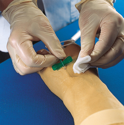
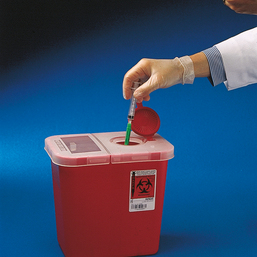
Reactions and Complications
Any medication has the potential to be harmful if it is not administered properly.1 Technologists must be aware of possible untoward medication reactions and be able to recognize and report signs and symptoms of side effects as they occur.2 The technologist who prepares a medication should also perform the administration.
Reactions can be mild, moderate, or severe. Mild reactions can include a sensation of warmth, a metallic taste, or sneezing. Moderate reactions can manifest as nausea, vomiting, or itching. Finally, a severe, or anaphylactic, reaction can cause a respiratory or cardiac crisis. The treatment for each category of reaction should be established in the procedures of each facility or department. The role of the radiologic technologist in the case of a reaction should also be defined in these documents. Competent professional standards of practice for the technologist include monitoring the patient’s vital signs before, during, and after the injection of a contrast medium or certain types of medications. The specific monitoring criteria should be established by institutional policy. If an untoward event should occur, responding personnel would have access to important information about the patient’s condition before the event occurred.
Every health care provider should be familiar with emergency procedures in the work environment. Emergency crash carts contain many medications and pieces of equipment that require regular review. Proficiency in the operation of equipment and the administration of medications must be maintained. The technologist must have the knowledge, proficiency, and confidence to manage crisis situations.
Infiltration is another complication associated with the administration of contrast media or medications. This complication occurs when the medication or contrast material enters the soft tissue instead of the vein.1 Signs of infiltration are swelling, redness, burning, and pain. The most common cause of extravasation is needle displacement. If infiltration occurs, the procedure should be stopped immediately, and the venous access should be discontinued. The physician must be notified, and specific treatment instructions must be requested. Common therapies for infiltration are (1) the application of ice if less than 30 minutes have passed since the infiltration occurred or (2) the application of warm, wet compresses if the infiltration occurred more than 30 minutes previously.1
Documentation
In the administration of any medication, the radiologic technologist should always observe five “rights of medication administration”:
The right patient must receive the medication. The identity of the patient must be confirmed before the medication is administered. Methods of patient identification include checking the patient’s wristband and asking the patient to restate his or her name. If the patient is unable to speak, seek assistance in identifying the patient from a family member or significant other. Ensuring that the right medication is administered requires that the name of the medication be verified at least three times: during the selection process, during the preparation, and immediately before the administration. The amount of medication is determined by the physician or by departmental protocols. The right route, right amount, and right time are determined by the physician, the type of medication, and the procedure.
Documentation of the five rights of medication administration should be included in every patient’s permanent medical record. In addition to these five rights, the documentation should include the size, type, and location of the needle; the number of venipuncture attempts; and the identity of the health care personnel who performed the procedure. Information about how the patient responded to the procedure should also be documented. The following is an example of correct documentation techniques for a technologist performing venipuncture and administering a medication:
4-15-99 at 0900 a venous access on Mr. John Q Public was performed using an 18-gauge angiocatheter. The access was established in the dorsum of the left hand after one attempt. Then 100 mL of [the specific name of the medication] was administered by IV push via the access. The patient tolerated the injection procedure and medication without complaints of pain or discomfort and with no unexpected side effects. (Sandy R. Ray, RT)
The objective of medication therapy and administration is to provide the maximal benefit to the patient with the minimal harm. Medications are intended to help maintain health, treat or prevent disease, relieve symptoms, alter body processes, and diagnose disease. All medications are not ideal in their effects on the human body. It is important that health care providers understand their role and responsibilities in the administration of medications. Because the medications used by the radiologic technologist are imperfect, caution for the patient’s well-being and skill in the administration of the medications are priorities. Patients have the right to expect that the personnel who administer medications are informed about dosages, actions, indications, adverse reactions, interactions, contraindications, and special considerations. Education, training, licensing, and experience are crucial in establishing competency in this area of practice.
1Long BW: Radiography of cutaneous urinary diversions, Radiol Technol 60:109, 1988.
1Rowntree LG et al: Roentgenography of the urinary tract during excretion of sodium iodide, JAMA 8:368, 1923.
2Roseno A, Jepkins H: Intravenous pyelography, Fortschr Roentgenstr 39:859, 1929. Abstract: AJR Am J Roentgenol 22:685, 1929.
1Hope JW, Campoy F: The use of carbonated beverages in pediatric excretory urography, Radiology 64:66, 1955.
2Berdon WE et al: Prone radiography in intravenous pyelography in infants and children, AJR Am J Roentgenol 103:444, 1968.
1Rolleston GL, Reay ER: The pelvi-ureteric junction, Br J Radiol 30:617, 1957.
2Cook IK et al: Determination of the normal position of the upper urinary tract in the lateral abdominal urogram, Radiology 99:499, 1971.
1Evans JA et al: Nephrotomography, AJR Am J Roentgenol 71:213, 1954.
2Evans JA: Nephrotomography in the investigation of renal masses, Radiology 69:684, 1957.
1Lindblom K: Percutaneous puncture of renal cysts and tumors, Acta Radiol 27:66, 1946.
2Lindblom K: Diagnostic kidney puncture in cysts and tumors, AJR Am J Roentgenol 68:209, 1952.
1Wickbom I: Pyelography after direct puncture of the renal pelvis, Acta Radiol 41:505, 1954.
2Weens HS, Florence TJ: The diagnosis of hydronephrosis by percutaneous renal puncture, J Urol 72:589, 1954.
3Casey WC, Goodwin WE: Percutaneous antegrade pyelography and hydronephrosis, J Urol 74:164,1955.
1Stevens WE, Smith SP: Roentgenological examination of the female urethra, J Urol 37:194, 1937.
2Barnes AC: A method for evaluating the stress of urinary incontinence, Am J Obstet Gynecol 40:381, 1940.
1Hodgkinson CP et al: Urethrocystograms: metallic bead chain technique, Clin Obstet Gynecol 1:668, 1958.
1Klawon Sister MM: Urethrocystography and urinary stress incontinence in women, Radiol Techn 39:353, 1968.
1Kowalczyk N, Donnett K: Integrated patient care for the imaging professional, St Louis, 1996, Mosby.
1Tortorici M: Administration of imaging pharmaceuticals, Philadelphia, 1996, Saunders.
1Tortorici M: Administration of imaging pharmaceuticals, Philadelphia, 1996, Saunders.
2Kowalczyk N, Donnett K: Integrated patient care for the imaging professional, St Louis, 1996, Mosby.
1Managing IV therapy: skillbuilders, Springhouse, PA, 1991, Springhouse.
2Hoeltke L: The complete textbook of phlebotomy, ed 3, Albany, NY, 2006, Delmar.
1Smith S et al: Clinical nursing skills: basic to advanced skills, ed 6, Stamford, CT, 2003, Appleton & Lange.
2Adler AM, Carlton RR: Introduction to radiography and patient care, ed 4, Philadelphia, 2007, Saunders.
1Strasinger S, DiLorenzo M: Phlebotomy workbook for the multiskilled healthcare professional, ed 2, Philadelphia, 2003, FA Davis.
1Steele J: Practical IV therapy, Springhouse, PA, 1988, Springhouse.
1Adler AM, Carlton RR: Introduction to radiography and patient care, ed 4, Philadelphia, 2007, Saunders.
1Weinstein SM: Plumer’s principles and practice of intravenous therapy, ed 8, Boston, 2006, Little, Brown.
1Ehrlich R, McCloskey ED, Daly J: Patient care in radiography, ed 6, St Louis, 2004, Mosby.
1Kowalczyk N, Donnett K: Integrated patient care for the imaging professional, St Louis, 1996, Mosby.
2Adler AM, Carlton RR: Introduction to radiography and patient care, ed 3, Philadelphia, 2003, Saunders.
1Tortorici M: Administration of imaging pharmaceuticals, Philadelphia, 1996, Saunders.