MAMMOGRAPHY
Summary of mammography projections
Routine projections of the breast
Routine projections of the augmented breast
Routine projections of the male breast
Significant mammographic findings
Localization of nonpalpable lesions
Ductography (examination of milk ducts)
Full-field digital mammography
Breast magnetic resonance imaging
SUMMARY OF PROJECTIONS
Principles of Mammography
INTRODUCTION AND HISTORICAL DEVELOPMENT
The worldwide incidence of breast cancer is increasing. In the United States, one in eight women who live to age 95 years develops breast cancer sometime during her lifetime. Breast cancer is one of the most common malignancies diagnosed in women; only lung cancer has a greater overall mortality in women. Research has failed to reveal the precise etiology of breast cancer, and only a few major factors, such as family history, are known to increase a woman’s risk of developing the disease. Most women who develop breast cancer have no family history of the disease, however.
Despite its frequency, breast cancer is one of the most treatable cancers. Because this malignancy is most treatable when it is detected early, efforts have been directed toward developing breast cancer screening and early detection methods. Breast cancer mortality rates have declined by 2.3% per year from 1990-2000 in all women, with larger increases in women younger than 50 years of age. This decline is most likely the result of earlier detection and improved treatments.1
Mammography is the most important innovation in breast cancer control since the radical mastectomy was introduced by Halstead in 1898. The primary goal of mammography is to detect breast cancer before it is palpable. The combination of early detection, diagnosis, and treatment has resulted in a steady increase in survival rates. The overall mortality rate for breast cancer has finally decreased for American women.
Before the radical mastectomy was introduced, breast cancer was considered a fatal disease. Less than 5% of patients survived 4 years after diagnosis, and the local recurrence rate for surgically treated breast cancer was greater than 80%. Radical mastectomy increased the 4-year survival rate to 40% and reduced the rate of local recurrence to approximately 10%. No additional improvement in breast cancer survival rates occurred over the next 60 years. Some of the principles of breast cancer management were developed during this time, however, and these remain valid:
1. Patients in the early stage of the disease respond well to treatment.
2. Patients with advanced disease do poorly.
3. The earlier the diagnosis, the better the chances of survival.
Reflecting these principles, the theory of removing all palpable breast masses in hopes of finding earlier cancers was developed, and it was recognized that careful physical examination of the breast could detect some early breast cancers. Most patients with breast cancer still were not diagnosed until their disease was advanced, however. This fact, coupled with the dismal breast cancer survival statistics, highlighted the need for a tool for the early detection of breast cancer. Mammography filled that need (Fig. 23-1).
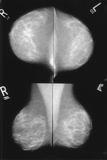
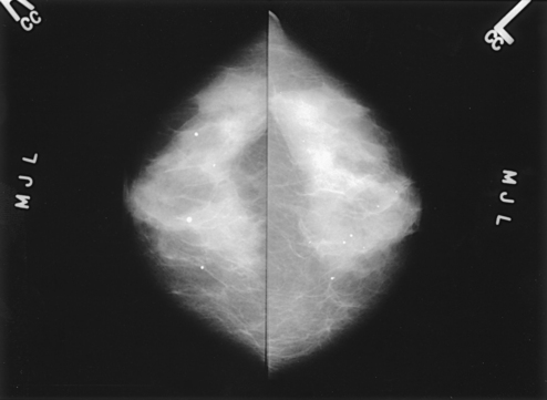
Fig. 23-1 Four-image, bilateral mammogram of a 37-year-old woman. Craniocaudal and mediolateral oblique projections show normal, symmetric breast parenchyma.
In 1913, Soloman, a German physician, reported the radiographic appearance of breast cancers. Using radiographic studies of cancerous breasts removed at surgery, he described the mechanism of how breast cancer spread. The first published radiograph of a living person’s breast, made by Kleinschmidt, appeared in a 1927 German medical textbook on malignant tumors. Although publications on mammography appeared in South America, the United States, and Europe during the 1930s, the use of mammography for the diagnosis of breast cancer received little clinical interest. A few pioneers, including LeBorgne in Uruguay, Gershon-Cohen in the United States, and Gros in Germany, published excellent comparisons of mammographic and pathologic anatomy and developed some of the clinical techniques of mammography. At that time, the significance of breast microcalcifications was also well understood.
By the mid-1950s, mammography was considered a reliable clinical tool because of such refinements as low-kilovoltage x-ray tubes with molybdenum targets and high-detail, industrial-grade x-ray film. During this time, Egan in the United States and Gros in Germany popularized the use of mammography for diagnosing and evaluating breast cancer. Breast xerography was introduced in the 1960s and was popularized by Wolfe and Ruzicka. Xerography substantially reduced the radiation dose received by the patient compared with the dose received using industrial-grade x-ray film (Fig. 23-2). Because many physicians found xerographic images easier to understand and evaluate, xeromammography became widely used for evaluating breast disease. The first attempts at widespread population screening began at this time.
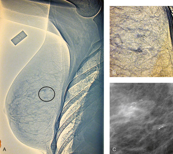
Fig. 23-2 A, Right lateral xeromammogram, circa 1981. B, Circled area is photographically magnified showing small area of microcalcifications. C, Film-screen magnification study 10 years later shows same calcifications. This was proven to be ductal carcinoma in situ on biopsy.
The combination of higher resolution, faster speed x-ray film and an intensifying screen was first introduced by the duPont Company. As a result, radiation exposure to the patient was reduced even more. Improved screen-film combinations were developed by Kodak and duPont in 1975. By this time, extremely high-quality mammography images could be produced with very low patient radiation exposures. Since 1975, faster lower dose films, magnification techniques, and grids for scatter reduction have been introduced. It is now known that high-quality mammography, careful physical examination, and monthly breast self-examination (BSE) can result in the detection of breast cancer at an early stage—when it is most curable.
The Breast Cancer Detection Demonstration Project (BCDDP) was implemented in 1973. In this project, 280,000 women underwent annual screening for breast cancer for 5 years at 29 locations throughout the United States. Organized by the American Cancer Society and the National Cancer Institute, this project showed unequivocally that screening, physical examination, mammography, and BSE could provide an early diagnosis. In the BCDDP, more than 41% of all the cancers were found using only mammography, and an even greater proportion of early breast cancers were found only with mammography. The BCDDP was not designed to show that early detection of breast cancer would lead to increased survival rates, but definite evidence from carefully controlled studies in the Netherlands, Sweden, and Germany showed that early diagnosis of breast cancer leads to an increase in curability. In the United States, the Health Insurance Plan study in New York City performed mammography screenings on women older than 50 years and showed the same benefits in reduced mortality rates after early diagnosis of breast cancer.
Mammography must be performed well to be fully effective. In 1992, the Mammography Quality Standards Act (MQSA) was implemented to mandate the maintenance of high-quality breast cancer screening programs. The American College of Radiology (ACR) had been a proponent of high standards in breast imaging since 1967 and implemented an optional Mammography Accreditation Program in 1989. In 1994, mammography became the only radiographic examination to be fully regulated by the federal government. MQSA requires formal training and continuing education for all members of the breast imaging team. In addition, imaging equipment must be inspected regularly, and all quality assurance activities must be documented. Facilities are also required to provide protocols documenting responsibility for communicating mammogram results to the patient and the referring physician, providing follow-up, tracking patients, and monitoring outcomes. The goal of MQSA is for high-quality mammography to be performed by individuals most qualified to do so and by individuals who are willing to accept full responsibility for providing that service with continuity of care.
RISK VERSUS BENEFIT
In the mid-1970s, the media-influenced public perception was that radiation exposure from diagnostic x-rays would induce more breast cancers than would be detected. Although radiation dosage during a mammography examination has decreased dramatically since the 1970s, fear of radiation exposure still causes some women to refuse mammography, and many women who undergo the examination are concerned about exposure levels and the resultant risk of carcinogenesis. To assuage these fears, the radiographer must understand the relationship between breast irradiation and breast cancer and the relative risks of mammography in light of the natural incidence of breast cancer and the potential benefit of the examination. No direct evidence exists to suggest that the small doses of diagnostic x-rays used in mammography can induce breast cancer. It has been shown, however, that large radiation doses can increase the incidence of breast cancer and that the risk is dose-dependent. The evidence to support the increased risk of breast cancer from breast irradiation comes from studies of three groups of women in whom the incidence of breast cancer increased after they were exposed to large doses of radiation: (1) women exposed to the atomic bombs at Hiroshima and Nagasaki, (2) women with tuberculosis who received multiple fluoroscopic examinations of the chest, and (3) women who were treated with radiation for postpartum mastitis. The radiation dose received by these women (600 to 700 rads) was many times higher, however, than the dose received from mammography.
Mean glandular dose provides the best indicator of radiation risk to a patient. In 1997, the average mean glandular dose for a two-projection screen-film-grid mammogram for all facilities in the United States inspected under MQSA was 320 mrad.1 Using that level as a gauge, the lifetime risk of mortality from mammography-induced radiation is 5 deaths per 1 million patients. In other terms, the risk received from having an x-ray mammogram using a screen-film combination is equivalent to smoking several cigarettes, driving 60 miles in an automobile, or being a 60-year-old man for 10 minutes.
Fig. 23-3 shows a chart displaying average values for mean glandular dose and estimates of image quality in mammography for the period from the early 1970s to 2005. Doses in mammography have consistently decreased with time, with the most substantial reductions in dose occurring from the early 1970s to the early 1980s. Image quality data are presented from the mid-1980s to the present and show consistent improvement with time.2
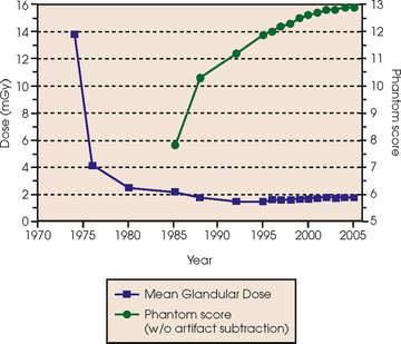
Fig. 23-3 Average values for mean glandular dose and estimates of image quality in mammography for the period from the early 1970s to 2005.
An important observation in the previously mentioned population studies is that the breast tissue of young women in their teenage years to early 20s seems to be much more sensitive to radiation than the breast tissue of women older than 30 years. Because breast irradiation is a concern, radiologic examinations need to be performed with only the radiation dose that is necessary for providing accurate detection.
BREAST CANCER SCREENING
The frequency with which women should undergo screening mammography depends on their age and personal risk of developing breast cancer. The current recommendations from the American Cancer Society and the ACR are that all women older than 40 years should undergo annual mammography and should continue yearly mammography for as long as they are in reasonably good health otherwise. A baseline examination made sometime before the onset of menopause is useful for comparison during subsequent evaluations. High-risk patients should consider beginning screening mammography at an earlier age.
The term screening mammography is applied to a procedure performed on an asymptomatic patient or a patient who presents without any known breast problems. For a procedure to be used as a screening method, it must meet the following criteria:
Mammography is a relatively simple procedure that takes only about 15 minutes to complete. The acceptability of mammography, which is the only radiographic procedure used to screen cancer, has been confirmed in numerous studies. Mammography cannot detect all cancerous lesions, however. An annual clinical breast examination is recommended by the American Cancer Society. Many physicians also recommend that women perform monthly BSEs. Even when mammography is performed properly, approximately 10% of cancers remain radiographically occult, particularly in dense breasts and augmented breasts. Even so, mammography has greater sensitivity and specificity for detecting breast tumors than any other currently available noninvasive diagnostic technique. When compared with magnetic resonance imaging (MRI), ultrasonography, and digital techniques, mammography is more cost-effective and more reproducible when quality control standards are maintained. Mammography must be performed properly to maintain these characteristics, however. As with other imaging modalities, high-quality mammography requires an extremely dedicated staff with the appropriate training and expertise.
Breast cancer screening studies have shown that early detection is essential to reducing mortality and that the most effective approach is to combine clinical breast examination with mammography at directed intervals. Although massive screening efforts initially may seem cost prohibitive, the actual cost of screening in the long-term is much less than the expenses involved in caring for patients with advanced breast disease. To this end, screening patients at high risk for breast cancer with the addition of annual breast MRI has been added to screening recommendations.
The preceding paragraphs describe the screening of patients who do not have significant breast symptoms. All patients with clinical evidence of significant or potentially significant breast disease should undergo a diagnostic mammogram and subsequent work-up as necessary. Diagnostic mammograms are problem-solving examinations in which specific projections are obtained to rule out cancer or to show a suspicious area seen on the routine screening projections. They are also indicated if a woman presents with a palpable mass or other symptom. The area of interest may be better shown using image enhancement methods, such as spot compression and magnification technique. Further work-up may be necessary if mammography does not show a correlative mass. Alternative imaging modalities such as ultrasonography are often used to complete a successful work-up. The radiologist and radiographer direct and conduct the diagnostic mammogram to facilitate an accurate interpretation.
Although most diagnostic mammograms conclude with probable benign findings, some women are asked to return for subsequent mammograms in 3 or 6 months to assess for interval changes. Other women must consult with a specialist or surgeon about possible options such as fine-needle aspiration biopsy (FNAB), core biopsy, or excisional biopsy.
Although it is an excellent tool for detecting breast cancer, mammography does not permit diagnosis of breast cancer. Some lesions may appear consistent with malignant disease but turn out to be completely benign conditions. Breast cancer can be diagnosed only by a pathologist through the evaluation of tissue extracted from the lesion. After interpreting the diagnostic work-up, the radiologist must carefully determine whether surgical intervention is warranted.
RISK FACTORS
Assessing a woman’s risk for developing breast cancer is complicated. An accurate patient history must be elicited to identify potential individual risk factors. The radiologist considers these known risks after interpreting the mammogram. Other than gender, factors that are known to influence the development of breast cancer include age, hormonal history, and family history.
Hormonal history
Hormones influence the glandular tissue of the breast during breast development, pregnancy, and lactation; however, hormone levels decline at the onset of menopause. As a result, the glandular breast tissue is more sensitive to carcinogens during menarche. High-risk women include women with early menses (beginning before age 12 years), late menopause (occurring after 52 years of age), first birth after age 30 years, or nulliparity.
Family history
A woman whose daughter, sister, or mother previously developed breast cancer, especially at an early age, is at higher risk of developing the disease. Studies have shown, however, that only 13.6% of known breast cancers are found in women with a family history of the disease. A true genetic disorder has been identified in only 5% to 10% of women with breast cancer.1 Although family history is an important risk factor, women with no family history should be aware that they are also at risk.
In 1994, researchers isolated two breast cancer genes—BRCA1 and BRCA2. Commercial screening tests subsequently were developed. Studies have found that men and women with these genes have a higher risk of developing not only breast cancer but also other cancers, such as ovarian cancer and testicular cancer. Widespread genetic testing has raised ethical concerns associated with identifying appropriate candidates for genetic screening and determining what is done with the information derived from the testing. These concerns have been addressed; the Genetic Information Nondiscrimination Act (GINA) became a federal law in 2008.
Breast
The terms breast and mammary gland are often used synonymously. Anatomy textbooks tend to use the term mammary gland, whereas radiography textbooks tend to use the term breast. The breasts (mammary glands) are lobulated glandular structures located within the superficial fascia of the anterolateral surface of the thorax of both males and females. The mammary glands divide the superficial fascia into anterior and posterior components. The mammary tissue is completely surrounded by fascia and is enveloped between the anterior and posterior layers of the superficial fascia. In females, the breasts are secondary sex characteristics and function as accessory glands to the reproductive system by producing and secreting milk during lactation. In males, the breasts are rudimentary and without function. Male breasts are only rarely subject to abnormalities, such as neoplasms, that require radiologic evaluation.
Female breasts vary considerably in size and shape, depending on the amount of fat and glandular tissue and the condition of the suspensory ligaments. Each breast is usually cone-shaped, with the base or posterior surface of the breast overlying the pectoralis major and serratus anterior muscles. These muscles extend from the second or third rib inferiorly to the sixth or seventh rib and from near the lateral margin of the sternum laterally toward the anterior axillary plane. An additional portion of breast tissue, the axillary prolongation or axillary tail (AT), extends from the upper lateral base of the breasts into the axillary fossa (Fig. 23-4).
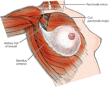
Fig. 23-4 Relationship of breast to chest wall. Note extension of breast tissue posteriorly into axilla.
The breast tapers anteriorly from the base, ending in the nipple, which is surrounded by a circular area of pigmented skin called the areola. The breasts are supported by Cooper ligaments, suspensory ligaments that extend from the posterior layers of the superficial fascia through the anterior fascia into the subcutaneous tissue and skin. It is the condition of these ligaments, and not the relative fat content, that gives the breasts their firmness or lack of firmness.
The adult female breast consists of 15 to 20 lobes, which are distributed such that more lobes are superior and lateral than inferior and medial. Each lobe is divided into many lobules, which are the basic structural units of the breast. The lobules contain the glandular elements, or acini. Each lobule consists of several acini, numerous draining ducts, and the interlobular stroma or connective tissue. These elements are part of the breast parenchyma and participate in hormonal changes. By the late teenage years to early 20s, each breast contains several hundred lobules. The lobules tend to decrease in size with increasing age and particularly after pregnancy—a normal process called involution.
The openings of each acinus join to form lactiferous ductules that drain the lobules, which join to form 15 to 20 lactiferous ducts, one for each lobe. Several lactiferous ducts may combine before emptying directly into the nipple. As a result, there are usually fewer duct openings on the nipple than there are breast ducts and lobes. The individual lobes are incompletely separated from each other by the Cooper ligaments. The space between the lobes also contains fatty tissue and additional connective tissue. A layer of fatty tissue surrounds the gland except in the area immediately under the areola and nipple (Fig. 23-5).
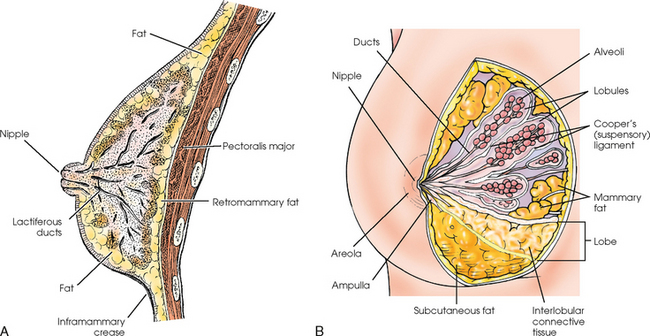
Fig. 23-5 A, Sagittal section through female breast, illustrating structural anatomy. B, Breast anterior view.
The lymphatic vessels of the breast drain laterally into the axillary lymph nodes and medially into the chain of internal mammary lymph nodes (see Fig. 25-6). Approximately 75% of the lymph drainage is toward the axilla, and 25% of the drainage is toward the internal mammary chain. The number of axillary nodes varies from 12 to 30 (sometimes more). The axilla is occasionally radiographed during breast examinations to evaluate the axillary nodes. The internal mammary nodes are situated behind the sternum and manubrium and, if enlarged, are occasionally visible on a lateral chest radiograph.
The radiographer should take into account breast anatomy and patient body habitus to image as much breast tissue as possible successfully. Image receptor (IR) size must be appropriate for the breast being imaged. Larger breasts would not be entirely shown on small IRs. Conversely, smaller breasts should not be imaged on larger IRs because (1) other body structures may interfere with the compression device and produce an unacceptable image, and (2) the pectoral muscle and the skin are likely to become taut from upward stretching of the arm, preventing the breast tissue from being completely pulled onto the film.
The natural mobility of the breast is also an important consideration. The lateral and inferior aspects of the breast are mobile, whereas the medial and superior aspects are fixed. The breast should always be positioned by moving the mobile aspects toward the fixed tissues. Likewise, the radiographer should avoid moving the compression paddle against fixed tissues because this would cause less breast tissue to be imaged.
Tissue Variations
The glandular and connective tissues of the breasts are soft tissue–density structures. The ability to show radiographic detail within the breast depends on the fat within and between the breast lobules and the fat surrounding the breasts. The postpubertal adolescent breast contains primarily dense connective tissue and casts a relatively homogeneous radiographic image with little tissue differentiation (Fig. 23-6). The development of glandular tissue decreases radiographic contrast. During pregnancy, significant hypertrophy of glands and ducts occurs within the breasts. This change causes the breasts to become extremely dense and opaque. After the end of lactation, considerable involution of glandular and parenchymal tissues usually occurs, and these tissues are replaced with increased amounts of fatty tissue. Fat accumulation varies markedly among individuals. This normal fat accumulation significantly increases the natural radiographic contrast within the breasts (Fig. 23-7). The breasts of patients with fibrocystic parenchymal conditions may not undergo this involution (Fig. 23-8).
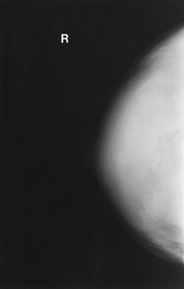
Fig. 23-6 Craniocaudal projection of normal breast in a 19-year-old woman who has never been pregnant. Note dense glandular tissues with small amounts of fat. In women who do not become pregnant, the breasts may remain dense for many years.
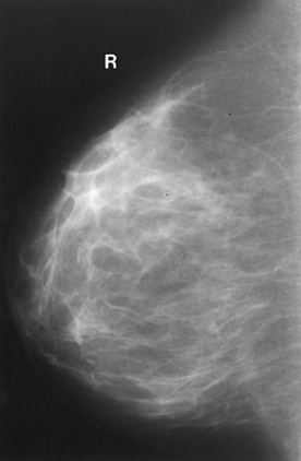
Fig. 23-7 Mediolateral projection of normal breast in a 24-year-old woman who has had two pregnancies. Note decreased volume of glandular tissue and increased amount of fat.
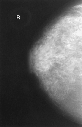
Fig. 23-8 Craniocaudal projection of breast of a 42-year-old woman with fibrocystic condition, illustrating prominent dilated ducts.
The glandular and connective tissue elements of the breast can regenerate as needed for subsequent pregnancies. After menopause, the glandular and stromal elements undergo gradual atrophy (Fig. 23-9). External factors such as surgical menopause and ingestion of hormones may inhibit this normal process. From puberty through menopause, mammotrophic hormones influence cyclic changes in the breasts. The glandular and connective tissues are in a state of constant change (Fig. 23-10).
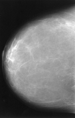
Fig. 23-9 Craniocaudal projection of normal breasts of a 68-year-old woman. Most of the glandular tissue is atrophic. Some glandular tissue remains in lateral breast posteriorly and in retroareolar area.
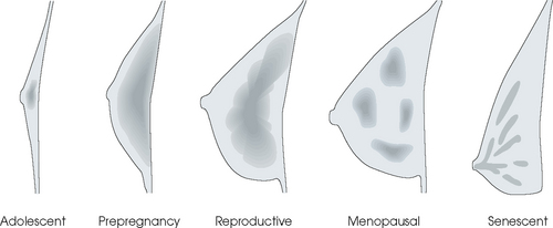
Fig. 23-10 Diagrammatic profile drawings of breast, illustrating most likely variation and distribution of radiographic density (shaded areas) related to the normal life cycle from adolescence to senescence. This normal sequence may be altered by external factors, such as pregnancy, hormone medications, surgical menopause, and fibrocystic breast condition.
SUMMARY OF PATHOLOGY
| Condition | Definition |
| Breast carcinoma | Malignant new growth composed of epithelial cells |
| Calcification | Deposit of calcium salt in tissue; characteristics may suggest either benign or malignant processes |
| Cyst | Closed epithelial sac containing fluid or a semisolid substance |
| Epithelial hyperplasia | Proliferation of the epithelium of the breast |
| Fibrosis | Formation of fibrous tissue in the breast |
| Tumor | New tissue growth where cell proliferation is uncontrolled |
| Fibroadenoma | Benign tumor of breast containing fibrous elements |
| Intraductal papilloma | Benign, neoplastic papillary growth in a duct |
Breast Imaging
EVOLUTION OF MAMMOGRAPHY SYSTEMS
Because the breast is composed of tissues with very similar densities and effective atomic numbers, little difference in attenuation is noticed when conventional x-ray equipment and technique are used. Manufacturers have developed imaging systems that optimally and consistently produce images with high contrast and resolution.
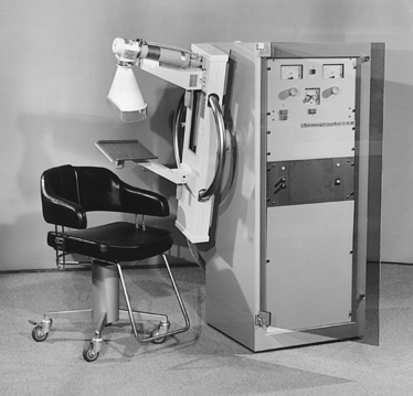
Diligent research and development began in the 1960s, and the first dedicated mammography unit was introduced in 1967 by CGR (France) (Fig. 23-11). In the 1970s, increased awareness of the elevated radiation doses prevalent in mammography served as the catalyst for the rapid progression of imaging systems. In the 1970s and early 1980s, xeromammography, named for the Xerox Corporation that developed it, was widely used (see Fig. 23-2). This method used much less radiation than the direct-exposure, silver-based films that were available. Eventually, film manufacturers introduced several generations of mammography film-screen systems that used even less exposure and improved tissue visualization. Each subsequent new system showed improvement in contrast and resolution while minimizing patient dose.
In the 1980s, the ACR accreditation program established quality standards for breast imaging to optimize mammographic equipment, processors, and screen-film systems to ensure the production of high-quality images. This program was expanded in the 1990s to include quality control and personnel qualifications and training. The voluntary ACR program has become the model from which MQSA operates, and the ACR has been instrumental in designing the clinical practice guidelines for quality mammography in the United States. The evolution of mammography has resulted in the implementation of radiographic systems designed specifically for breast imaging.
MAMMOGRAPHY EQUIPMENT
In recent years, equipment manufacturers have produced dedicated mammography units that have high-frequency generators, various tube and filter materials, focal spot sizes that allow tissue magnification, and specialized grids to help improve image quality and streamlined designs and ergonomic patient positioning aids.
The high-frequency generators offer more precise control of kilovolt (peak) (kVp), milliamperes (mA), and exposure time. The linearity and reproducibility of the radiographic exposures using high-frequency generators is uniformly excellent. The greatest benefit of these generators may be the efficient waveform output that produces a higher effective energy x-ray beam per set kVp and mA. High-frequency generators are not as bulky, and they can be installed within the single-standing mammography unit operating on single-phase incoming line power, facilitating easy installation and creating a less intimidating appearance (Fig. 23-12).
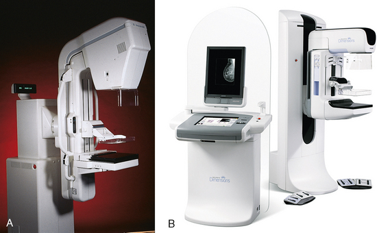
Fig. 23-12 A, Senographe DMR film-screen mammography unit by General Electric (Milwaukee, WI). B, Dimensions 3-D digital breast tomosynthesis unit by Hologic (Bedford, MA).
Specialized grids were developed for mammography during the 1980s to reduce scatter radiation and increase the image contrast in mammography. Most units employ moving linear focused grids, but some manufacturers have developed very specialized grids. The Hologic (Lorad) High Transmission Cellular (HTC) Grid employs a honeycomb-pattern, multidirectional design. All dedicated mammography units today, with the exception of slit-scan digital units, still employ grids.
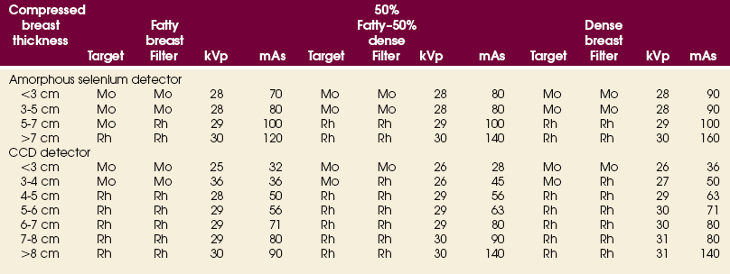
As manufacturers of dedicated mammography equipment sought to improve image quality, they have tried many different combinations of tube and filter materials. The most widely accepted combinations used at this time are molybdenum target with molybdenum filter (Mo/Mo), molybdenum target with rhodium filter (Mo/Rh), or rhodium target with rhodium filter (Rh/Rh). Mo/Mo is used most often, but Mo/Rh and Rh/Rh are used for better penetration of denser breasts with thick tissues.
The manufacturers also knew that technologists and physicians were interested in the comfort of their patients. They worked to make the examination more tolerable for patients, more ergonomically acceptable, and more efficient for the technologist performing the examination, while developing positioning aids to increase visualization of the tissue. Some of these aids include rounded corners on Bucky devices and compression paddles, the automatic release of compression after exposure, and foot pedal controls.
Finally, to bring mammography into the digital world was no simple task. To achieve the resolution and detail necessary for breast imaging, entire systems, from acquisition to diagnostic review workstations, were developed by competing manufacturers. Each of these included proprietary components that made integration of the units into a current picture archiving and communication system (PACS) network difficult. Integrating the Healthcare Enterprise has brought manufacturers of the many components necessary in a full field digital mammography (FFDM) system together to work out problems of compatibility and language allowing facilities the opportunity to transition more seamlessly into digital mammography
METHOD OF EXAMINATION
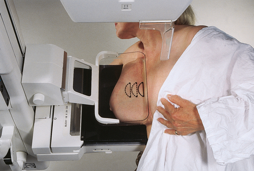
Because of the sensitivity of the radiographic films and imaging techniques used for mammography, artifacts are common. It is advisable to dress patients in open-front gowns because the breast must be bared for the examination. Patients should remove any deodorant and powder from the axilla region and breast because these substances can resemble calcifications on the resultant image. Before the breast is radiographed, a complete history is taken, and a careful physical assessment is performed, noting all biopsy scars, palpable masses, suspicious thickenings, skin abnormalities, and nipple alterations (Fig. 23-13).
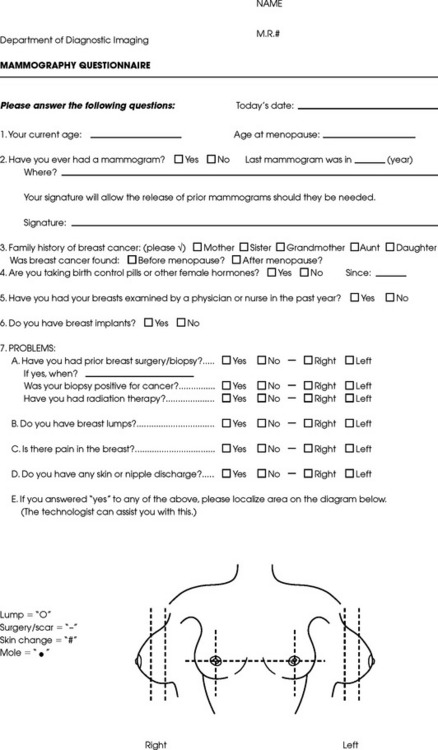
Fig. 23-13 Sample mammography patient questionnaire. (Courtesy The Permanente Medical Group, Inc., Richmond, Calif.)
Both breasts are routinely radiographed obtaining craniocaudal (CC) and mediolateral oblique (MLO) projections. Image enhancement methods, such as spot compression and magnification technique, are often useful. It is sometimes necessary to enhance images or vary the projections to characterize lesions and calcifications better. In symptomatic patients, the examination should not be limited to the symptomatic breast. Both breasts should be examined for comparison purposes and because significant radiographic findings may be shown in a clinically normal breast.
EXAMINATION PROCEDURES
This section describes procedures for conducting mammographic examinations using dedicated systems. The following steps should be taken:
• If possible, examine previous mammographic studies of patients who are undergoing subsequent mammography screening. These images should be evaluated for positioning, compression, and exposure factors to determine whether any improvement in image quality is required for the current study. Position the breast consistently so that any lesion can be accurately localized and a valid comparison can be made with prior studies.
• Determine the correct IR size for the patient, and use the smallest possible size to image all of the breast tissue fully. Positioning the breast on a surface that is too large causes the skin and muscles to overextend, reducing the amount of posterior tissue imaged.
• Explain the procedure simply and completely to the patient before beginning the examination. It should never be assumed that the patient is fully aware of what the mammographer is about to do, even if the patient has had prior examinations.
• In many cases, the routine projections do not sufficiently show all of the breast tissue, and additional projections may be necessary. To allay patient concerns, the mammographer should explain to the patient before beginning the procedure why additional projections are sometimes needed and that they do not indicate a potential problem.
• Before positioning the patient’s breast and applying compression, consider the natural mobility of the breast so that patient discomfort can be minimized. The inferior and lateral portions of the breast are mobile, whereas the superior and medial portions are fixed. Whenever possible, the mobile tissues should be moved toward the fixed tissues.
• For each of the two basic breast projections, ensure that the breast is firmly supported and adjusted so that the nipple is directed forward.
• Profile the nipple, if possible. Obtaining an image of the posterior breast tissue should be the primary consideration, and positioning of the nipple in profile is not always possible. An additional projection to profile the nipple can be obtained if necessary. Alternatively, a marker may be used to locate clearly the nipple that is not in profile, in which case an additional image may not be needed.
• Apply proper compression to the breast. Compression is an important factor in achieving a high-quality mammogram. The primary objective of compression is to produce uniform breast thickness from the nipple to the posteriormost aspect of the breast. Properly applied compression spreads the breast so that the tissue thickness is more evenly distributed over the image and better separation of the glandular elements is achieved. A rigid, radiolucent mammography compression paddle facilitates breast compression. Generally, compression is applied initially using a hands-free control and then applied manually during the final phase of compression. The compression should be taut but not painful. The skin of a properly compressed breast should feel tight when lightly tapped with the fingertips. When evaluating images, compare the degree of compression with previous mammograms and note any variations. If a patient is unable to tolerate an adequate amount of compression, document this information on the patient history form for the radiologist.
• Place identification markers (Fig. 23-14) according to the following standard convention:
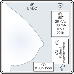
A Before processing, photographically expose a permanent identification label that includes the facility’s name and address; the date of the examination; and the patient’s name, age, date of birth, and medical number on the image. Include the initials of the person performing the examination on the identification label (C).
B On the IR near the patient’s axilla, place a radiopaque marker indicating the side examined and the projection used (Table 23-1).
TABLE 23-1
Labeling codes for mammographic positioning
From Bassett L et al, editors: Quality determinants of mammography, AHCPR Pub No 95-0632, Rockville, MD, 1994, U.S. Department of Health and Human Services.
C Label the mammography cassette with an identification number (Arabic numeral is suggested by the ACR).
• Mammography film labeling may also include the following:
D A separate date sticker or perforation
E A label indicating the technical factors used: kVp, milliampere-seconds (mAs), target material, degree of obliquity, density setting, exposure time, and compression thickness. This is often included on the automatic identification labeling system that most manufacturers now offer with their units.
F Facilities with more than one unit must identify the mammographic unit used (Roman numerals are suggested by the ACR).
G For FFDM images, all of the aforementioned pertinent information should be included in the DICOM header. The information should also be seen on the processed image or, if possible, used in a DICOM overlay that can be turned on or off as needed by the radiologist, to prevent interference while interpreting the image.
• For patients with palpable masses, a radiopaque (BB or X-spot) marker may be used to identify the location of the mass. A different type of radiopaque marker may be used to identify skin lesions, scars, or moles. This is determined by the policy of the facility.
• When using automatic exposure control (AEC), position the variable-position detector at the chest wall, the mid-breast, or the anterior breast, depending on breast composition and size. The appropriate location of the AEC detector must be determined for each individual patient. If possible, the detector should be placed under the most glandular portion of the breast, usually just posterior to the nipple.
• When reviewing images, assess contrast and density for optimal differentiation of breast tissues. Anatomic markers should be visible. The projections of one breast should be compared with the same projections of the contralateral breast to evaluate symmetry and consistency of positioning. All images should be absent of motion blur, artifacts, and skin folds. Images must be evaluated for potentially suspicious lesions and calcifications that may require image enhancement methods.
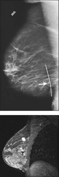
• To evaluate whether sufficient breast tissue is shown, the radiographer should measure the depth of the breast from the nipple to the chest wall on the CC and MLO projections. The posterior nipple line (PNL) is an imaginary line that is “drawn” obliquely from the nipple to the pectoralis muscle or edge of the image, whichever comes first on the MLO projection. On the CC projection, the PNL is “drawn” from the nipple to the chest wall or to the edge of the image, whichever comes first. The PNL on the CC should be within ⅓ inch (1 cm) of depth of the PNL on the MLO projection (Fig. 23-15).
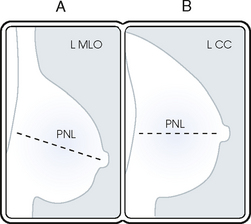
Fig. 23-15 A, MLO projection with PNL drawn. B, CC projection with PNL drawn. PNL of CC projection should be within 1 cm of PNL of MLO projection.
• Between examinations, use a disinfectant to clean the image receptor tray surface, compression paddle, patient handle grips, and face guard.
• If practical, a heating pad or commercially available mammography image receptor cover may be used to warm the image receptor tray surface and to enhance patient comfort.
• Mammography is a team effort involving the patient and the mammographer. Acknowledge the individual needs of each patient to facilitate the cooperation and trust necessary to complete the procedure successfully. The nature of the interaction between the radiographer and the patient is likely to determine whether the patient chooses to have subsequent mammograms.
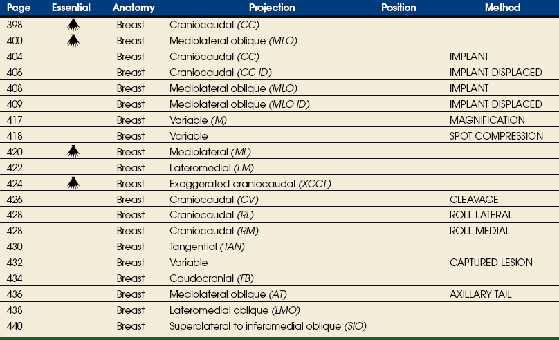
Summary of Mammography Projections
Before beginning to learn mammography projections, the student of radiography should carefully study the illustrative summary of mammography projections shown in the box. Familiarity with the different projection names and abbreviations would enhance the student’s understanding of the detailed discussions of the projections presented in this chapter.
DESCRIPTIVE TERMINOLOGY
Descriptive terminology has been developed for the referring physician, the technologist, and the radiologist all to communicate efficiently regarding an area of concern within a breast. When describing an area of concern, the laterality (right or left) must accompany the description (Fig. 23-16).
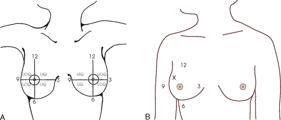
Fig. 23-16 A, Each breast is viewed as a clock and divided into four quadrants to describe the location of a lesion: UOQ, UIQ, LOQ, and LIQ. B, An abnormality should always be described in a consistent manner. For example, the location of the abnormality denoted by the x would be described as “right breast UOQ at approximately 10:30 position.”
The breast is divided into four quadrants: the upper-outer quadrant (UOQ), lower-outer quadrant (LOQ), upper-inner quadrant (UIQ), and lower-inner quadrant (LIQ). Clock-time is also used to describe the location of a specific area of concern within the breast: 2:00 in the right breast is in the UIQ, whereas 2:00 in the left breast is in the UOQ. This opposite labeling applies to all clock-times; it is important to identify the correct breast, clock-time, and quadrant. The distance of the abnormality from the nipple, which is the only fixed point of reference in the breast, is also noted. The terms subareolar and periareolar describe the area directly beneath the nipple and near (or around) the nipple area.
Routine Projections of the Breast
Mammography is routinely performed using the CC and MLO projections.
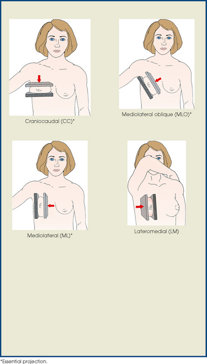
 CRANIOCAUDAL (CC) PROJECTION
• While standing on the medial side of the breast to be imaged, elevate the inframammary fold to its maximal height.
• Adjust the height of the C-arm to the level of the inferior surface of the patient’s breast.
• Use both hands to pull the breast gently onto the image receptor holder, while instructing the patient to press the thorax against the image receptor. Have the patient lean slightly forward from the waist.
• Keep the breast perpendicular to the chest wall. The technologist should use his or her fingertips to pull the posterior tissue gently forward onto the IR.
• Center the breast over the AEC detector, with the nipple in profile if possible.
• Immobilize the breast with one hand, being careful not to remove this hand until compression begins.
• Use the other hand to drape the opposite breast over the corner of the image receptor. This maneuver improves demonstration of the medial tissue.
• Have the patient hold onto the grab bar with the contralateral hand; this helps steady the patient as you continue positioning.
• Placing your arm against the patient’s back with your hand on the shoulder of the affected side, make certain the patient’s shoulder is relaxed and in external rotation.
• Rotate the patient’s head away from the affected side.
• Lean the patient toward the machine, and rest the patient’s head against the face guard.
• Make certain no other objects obstruct the path of the beam.
• With the hand on the patient’s shoulder, gently slide the skin up over the clavicle.
• Using the hand that is anchoring the patient’s breast, pull the lateral tissue on the image receptor without sacrificing medial tissue.
• Inform the patient that compression of the breast will be used. Bring the compression paddle into contact with the breast while sliding the hand toward the nipple.
• Slowly apply compression until the breast feels taut.
• Check the medial and lateral aspects of the breast for adequate compression.
• Instruct the patient to indicate whether the compression becomes uncomfortable.
• After full compression is achieved and checked, move the AEC detector to the appropriate position, and instruct the patient to stop breathing (Fig. 23-17).
Structures shown: The CC projection shows the central, subareolar, and medial fibroglandular breast tissue. The pectoral muscle is shown in approximately 30% of all CC images.1
The following should be clearly shown:
 The PNL extending posteriorly to the edge of the image and measuring within ⅓ inch (1 cm) of the depth of PNL on MLO projection (Fig. 23-18)
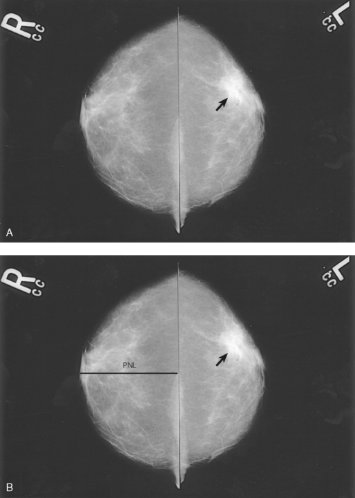
Fig. 23-18 A, Bilateral CC projection of a 63-year-old woman showing proper positioning. CC projection should include maximal medial breast tissue with nipples centered. Breast cancer (arrow) is visible on the left (L) breast. B, CC projections with PNL shown.
All medial tissue, as shown by the visualization of medial retroglandular fat and the absence of fibroglandular tissue extending to the posteromedial edge of image
Nipple in profile (if possible) and at midline, indicating no exaggeration of positioning
For emphasis of medial tissue, there may be exclusion of some lateral tissue
Pectoral muscle seen posterior to medial retroglandular fat in about 30% of properly positioned CC images
Slight medial skin reflection at the cleavage, ensuring adequate inclusion of posterior medial tissue
MEDIOLATERAL OBLIQUE (MLO) PROJECTION
• Determine the degree of obliquity of the C-arm apparatus by rotating the tube until the long edge of the image receptor is parallel to the upper third of the pectoral muscle of the affected side. The degree of obliquity should be between 30 degrees and 60 degrees, depending on the patient’s body habitus.
• Adjust the height of the C-arm so that the superior border is level with the axilla.
• Instruct the patient to elevate the arm of the affected side over the corner of the image receptor and to rest the hand on the adjacent handgrip. The patient’s elbow should be flexed and resting posterior to the image receptor.
• Place the upper corner of the image receptor as high as possible into the patient’s axilla between the pectoral and latissimus dorsi muscles so that the image receptor is behind the pectoral fold.
• Ensure that the patient’s affected shoulder is relaxed and leaning slightly anterior. Placing the flat surface of the hand along the lateral aspect of the breast, gently pull the patient’s breast and pectoral muscle anteriorly and medially.
• Holding the breast between the thumb and fingers, gently lift it up, out, and away from the chest wall.
• Rotate the patient’s body toward the image receptor while asking the patient to bend slightly at the waist.
• Center the breast with the nipple in profile if possible, and hold the breast in position.
• Hold the breast up and out by rotating the hand so that the base of the thumb and the heel of the hand support the breast (fingers are pointing away from breast).
• Inform the patient that compression of the breast will be used. Continue to hold the breast up and out while sliding the hand toward the nipple as the compression paddle is brought into contact with the breast.
• Slowly apply compression until the breast feels taut. The corner of the compression paddle should be inferior to the clavicle.
• Check the superior and inferior aspects of the breast for adequate compression.
• Instruct the patient to indicate whether the compression becomes uncomfortable.
• Pull down on the patient’s abdominal tissue to open the inframammary fold.
• Instruct the patient to hold the opposite breast away from the path of the beam.
• After full compression is achieved, move the AEC detector to the appropriate position, and instruct the patient to stop breathing (Fig. 23-19).
• Perpendicular to the base of the breast
• The C-arm apparatus is positioned at an angle determined by the slope of the patient’s pectoral muscle (30 to 60 degrees). The actual angle is determined by the patient’s body habitus: Tall, thin patients require steep angulation, whereas short, stout patients require shallow angulation.
Structures shown: The MLO projection usually shows most of the breast tissue, with emphasis on the lateral aspect and AT.
The following should be clearly shown:
PNL measuring within ⅓ inch (1 cm) of the depth of PNL on CC projection1 (While drawing the imaginary PNL obliquely following the orientation of breast tissue toward the pectoral muscle, use the fingers to measure its depth from nipple to pectoral muscle or to the edge of the image, whichever comes first [Fig. 23-20].)
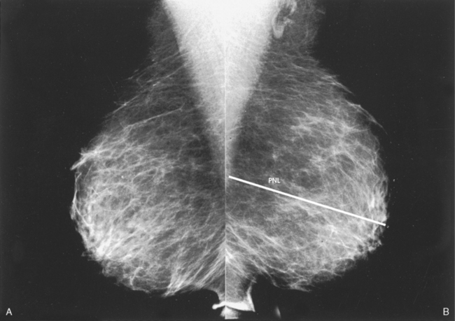
Fig. 23-20 A, MLO projections showing proper positioning. Images should include pectoral muscle to level of nipple, posterior breast tissue, and junction of inframammary fold and abdominal skin. B, PNL is shown.
Inferior aspect of the pectoral muscle extending to the PNL or below it if possible
Pectoral muscle showing anterior convexity to ensure relaxed shoulder and axilla
Deep and superficial breast tissues well separated when breast is adequately maneuvered up and out from the chest wall
Retroglandular fat well visualized to ensure inclusion of deep fibroglandular breast tissue
11Bassett L: Clinical image evaluation, Radiol Clin North Am 33:1027, 1995.
Routine Projections of the Augmented Breast
Mammography is clearly the preferred and most reliable technique for breast cancer screening. This technique has an 80% to 90% true-positive rate for detecting cancer in breasts that do not contain implants. For the millions of women in the United States who have undergone augmentation mammoplasty for cosmetic or reconstructive purposes, the true-positive (pathologic-mammographic) breast cancer detection rate decreases to approximately 60%, however, because implants can obscure 85% of breast structures, potentially hiding a small cancer that could normally be detected with mammography at an early and curable stage.
Successful radiography of an augmented breast requires a highly skilled mammographer. During the examination, precautions must be taken to avoid rupture of the augmentation device.
Mammography of the augmented breast presents a challenge that cannot be met with the standard two-image examination of each breast. An eight-radiograph examination is preferred whenever possible. The posterior and superior aspects of the augmented breast can be satisfactorily evaluated using the CC and MLO projections. These four images do not adequately show the surrounding breast parenchyma, however.
The initial two projections may be combined with the Eklund, or implant displaced (ID), technique. For the Eklund method, the implant is pushed posteriorly against the chest wall so that it is excluded from the image, and the breast tissue surrounding the implant is pulled anteriorly and compressed. This positioning improves compression of breast tissue and visualization of breast structures. The CC and MLO projections are often performed using the ID technique.
Complications frequently associated with breast augmentation include fibrosis, increased fibrous tissue surrounding the implant, shrinking, hardening, leakage, and pain. Because mammography alone cannot fully show all complications, ultrasonography and MRI are also used for breast examinations in symptomatic patients. Whether ultrasonography or MRI is used as the adjunct imaging after mammography for patients with suspected implant rupture varies from practice to practice.
Ultrasonography of the breast has proved useful in identifying implant leakage when implant rupture is suggested by mammographic findings and clinical examination and occasionally when leakage is not suspected. It has also successfully identified leakage that has migrated to the axillary lymph nodes. Although ultrasonography is not yet recommended as a screening modality for implant leakage, it has enhanced the mammographic examination.
MRI is currently the most commonly used modality for diagnostic evaluation of augmented breasts. Although MRI offers several diagnostic advantages, the cost and time-consuming nature of the procedure inhibits its use as a screening modality for patients who have undergone augmentation. It may be used as a screening tool for women who have undergone reconstruction after breast cancer surgery. MRI has proved useful as a preoperative tool in locating the position of an implant, identifying the contour of the deformity, and confirming rupture and leakage migration patterns. The sensitivity and specificity of MRI have been 94% and 97%.1
CRANIOCAUDAL (CC) PROJECTION WITH FULL IMPLANT
• Turn the AEC off, and preselect a manual technique.
• Follow the same positioning sequence as for the standard CC projection.
• Inform the patient that compression of the breast will be used. Bring the compression paddle into contact with the breast, and slowly apply enough compression to immobilize the breast only. Compression should be minimal. The anterior breast tissue should still feel soft.
• Select the appropriate exposure factors, and instruct the patient to stop breathing.
Structures shown: The image should show the entire implant and surrounding posterior breast tissue with suboptimal compression of the anterior fibroglandular breast tissue (Fig. 23-21).
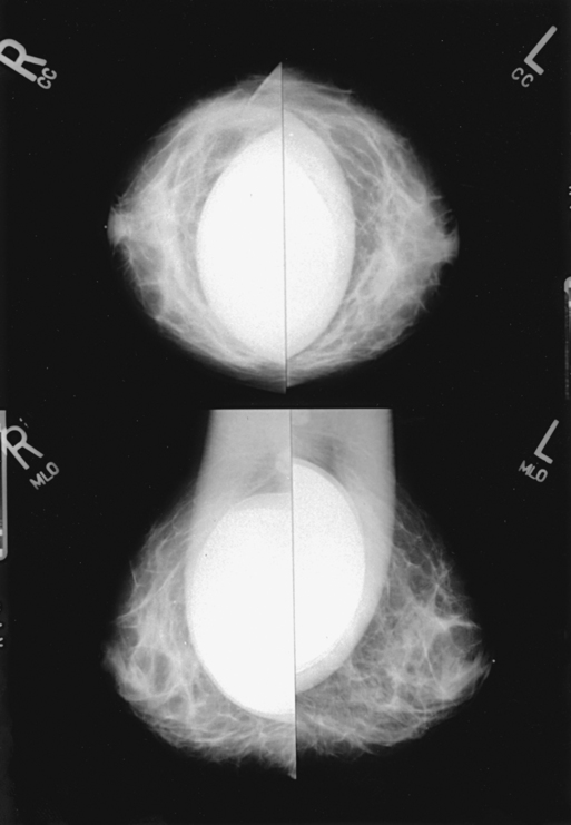
Fig. 23-21 Bilateral, four-image CC and MLO examination of augmented breasts of a 37-year-old woman. Implants have been surgically placed behind pectoral muscle. Additional radiographs should be obtained using Eklund (ID) technique to complete the eight-radiograph study (see Fig. 23-22).
Augmented Breast
CRANIOCAUDAL PROJECTION WITH IMPLANT DISPLACED (CC ID)
• While standing on the medial side of the breast to be imaged, elevate the inframammary fold to its maximal height.
• Adjust the height of the C-arm to the level of the inferior surface of the breast.
• Standing behind the patient, place both arms around the patient and locate the anterior border of the implant by walking the fingers back from the nipple toward the chest wall.
• When the anterior border of the implant has been located, gently pull the anterior breast tissue forward onto the image receptor (Fig. 23-22). Use the hands and the edge of the image receptor to keep the implant displaced posteriorly.
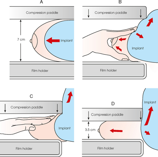
Fig. 23-22 A, Breast with implant and normal positioning techniques. B-D, Eklund technique of pushing implant posteriorly against chest wall, pulling breast anteriorly, and compressing tissue. (From Eklund GW et al: Improved imaging of the augmented breast, AJR Am J Roentgenol 151:469, 1988.)
• Center the breast over the AEC detector with the nipple in profile if possible.
• Hold the implant back against the chest wall. Slowly apply compression to the anterior skin surface, being careful not to allow the implant to slip under the compression paddle. As compression continues, the implant should be seen bulging behind the compression paddle.
• Apply compression until the anterior breast tissue is taut. Compared with the full-implant projection, an additional ¾ to 2 inches (2 to 5 cm) of compression should be achieved with the implant displaced.
• Instruct the patient to indicate whether the compression becomes uncomfortable.
• When full compression is achieved, move the AEC detector to the appropriate position and instruct the patient to stop breathing.
Structures shown: This projection shows the implant displaced posteriorly. The anterior and central breast tissue is seen projected free of superimposition with uniform compression and improved tissue differentiation (Fig. 23-23).
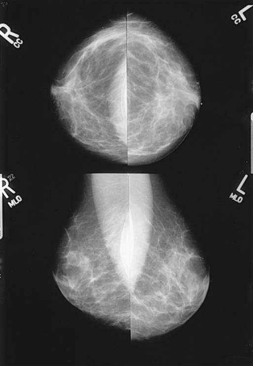
Fig. 23-23 Bilateral, four-image with ID examination of the same patient as in Fig. 23-20, using Eklund (ID) technique. Implants are pushed back for better visualization of surrounding breast tissue.
The following should be clearly shown:
Breast tissue superior and inferior to the implant pulled forward with the anterior breast tissue projected free of the implant
PNL extending posteriorly to edge of implant, measuring within ⅓ inch (1 cm) of depth of PNL on MLO projection with implant displaced
Implant along posterior edge of image, flattened against chest wall
Image sharpness enhanced by increased compression and reduced scatter
MEDIOLATERAL OBLIQUE (MLO) PROJECTION WITH FULL IMPLANT
• Turn the AEC off, and preselect a manual technique.
• Follow the same positioning sequence as for the standard MLO projection.
• Inform the patient that compression of the breast will be used. Continue to hold the breast up and out while sliding the hand toward the nipple as the compression paddle is brought into contact with the breast.
• Slowly apply enough compression to immobilize the breast only. Compression should be minimal, and the anterior breast tissue should still feel soft.
• Pull down on the patient’s abdominal tissue to open the inframammary fold.
• Select the appropriate exposure factors, and instruct the patient to stop breathing.
• Perpendicular to the image receptor
• The C-arm apparatus is positioned at an angle determined by the slope of the patient’s pectoral muscle (30 to 60 degrees). The actual angle is determined by the patient’s body habitus: Tall, thin patients require steep angulation, whereas short, stout patients require shallow angulation.
Structures shown: The image shows the entire implant and surrounding posterior breast tissue with suboptimal compression of the anterior fibroglandular breast tissue (see Fig. 23-20).
MEDIOLATERAL OBLIQUE PROJECTION WITH IMPLANT DISPLACED (MLO ID)
• Determine the degree of obliquity of the C-arm apparatus by rotating the tube until the long edge of the image receptor is parallel to the upper third of the pectoral muscle of the affected side. The degree of obliquity should be between 30 degrees and 60 degrees, depending on the patient’s body habitus.
• Adjust the height of the C-arm so that the superior border is level with the axilla.
• Instruct the patient to elevate the arm of the affected side over the corner of the image receptor and to rest the hand on the adjacent handgrip. The patient’s elbow should be flexed.
• Standing in front of the patient, locate the anterior border of the implant by walking the fingers back from the patient’s nipple toward the chest wall.
• After locating the anterior border of the implant, gently pull the anterior breast tissue forward onto the image receptor. Use the edge of the image receptor and the hands to keep the implant displaced posteriorly.
• Center the breast over the AEC detector with the nipple in profile if possible.
• Hold the anterior breast tissue up and out so that the base of the thumb and the heel of the hand support the breast (fingers are pointing away from breast).
• Hold the implant back against the chest wall. Slowly apply compression to the anterior skin surface, being careful not to allow the implant to slip under the compression paddle. As compression continues, the implant should be seen bulging behind the compression paddle.
• Apply compression until the anterior breast tissue is taut. Compared with the full-implant projection, an additional ¾ to 2 inches (2 to 5 cm) of compression should be achieved with the implant displaced.
• Instruct the patient to indicate whether the compression becomes uncomfortable.
• Pull down on the patient’s abdominal tissue to open the inframammary fold.
• Instruct the patient to hold the opposite breast away from the path of the beam.
• When full compression is achieved, move the AEC detector to the appropriate position and instruct the patient to stop breathing.
• Perpendicular to the image receptor
• The C-arm apparatus is positioned at an angle determined by the slope of the patient’s pectoral muscle (30 to 60 degrees). The actual angle is determined by the patient’s body habitus: Tall, thin patients require steep angulation, whereas short, stout patients require shallow angulation.
Structures shown: This image shows the implant displaced posteriorly. The anterior and central breast tissue is seen projected free of superimposition with uniform compression and improved tissue differentiation (see Fig. 23-22).
The following should be clearly shown:
Breast tissue superomedial and inferolateral to the implant with anterior breast tissue projected free of the implant
PNL extending obliquely to edge of implant, measuring within ⅓ inch (1 cm) of depth of PNL on CC projection with implant displaced
Implant projected over fibroglandular tissue, extending to posterior edge of image
Posterior breast tissue on inferior aspect of breast, extending to chest wall
Breast adequately maneuvered up and out from chest wall
Image sharpness enhanced by increased compression and reduced scatter
Routine Projections of the Male Breast
EPIDEMIOLOGY OF MALE BREAST DISEASE
In the United States, approximately 1300 men develop breast cancer every year, and one third die of the disease. Although most men who develop breast cancer are 60 years old and older, juvenile cases have been reported. Based on the medical literature, very few studies are being conducted to ascertain the relevance of breast cancer incidence in men. Nearly all male breast cancers are primary tumors. Because men have significantly less breast tissue, smaller breast lesions are palpable and diagnosed at early stages. Other symptoms of breast cancer in men include nipple retraction, crusting, discharge, and ulceration.
Gynecomastia, a benign excessive development of the male mammary gland, can make malignant breast lesions more elusive to palpation. Gynecomastia occurs in 40% of male breast cancer patients. A histologic relationship between gynecomastia and male breast cancer has not been definitely established, however. Because gynecomastia is caused by a hormonal imbalance, it is believed that abnormal hormonal function may increase the risk of male breast cancer. Other associated risk factors for male breast cancer include increasing age, positive family history, BRCA1 and BRCA2 gene mutations, and Klinefelter syndrome.1,2
Breast cancer treatment options are limited among male patients. Because men have less breast tissue, lumpectomy is not considered practical. A modified radical mastectomy is usually the preferred surgical procedure. Radiation and systemic therapy is considered when the tumor is located near the chest wall or if indicated by lymph node analysis. Similar to female breast cancer, the prognosis for male breast cancer is directly related to the stage of the disease at diagnosis. An early diagnosis indicates a better chance of survival. Survival rates among male patients with localized breast carcinomas are positive: 97% survive for 5 years.
MALE MAMMOGRAPHY
Male breast anatomy varies significantly from female breast anatomy in that the pectoral muscle is more highly developed in men. The radiographer must take this variance into consideration. The standard CC and MLO projections may be applied with success in many male patients (Figs. 23-24 through 23-27). For men (or women) with large pectoral muscles, the radiographer may perform the caudocranial (FB) projection instead of the standard CC because it may be easier to compress the inferior portion of the breast. In addition, the lateromedial oblique (LMO) projection may replace the standard MLO (see pp. 434-435 and 438-439).
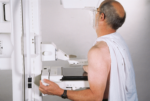
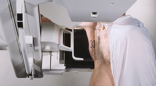
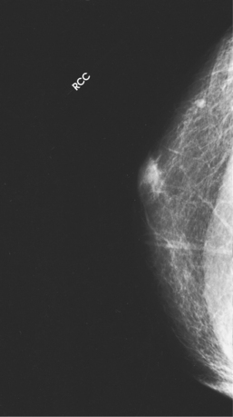
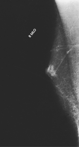
Fig. 23-27 MLO projection of the patient in Fig. 23-26.
These supplemental projections allow the radiographer to accommodate a patient with prominent pectoral muscles successfully. Some facilities also use narrower compression paddles (3 inches [8 cm] wide) for compressing the male breast or the small female breast.1 The smaller paddle permits the radiographer to hold the breast in position while applying final compression. A wooden spoon or spatula can also be used to hold the breast in place.
Because most men who undergo mammography present with outward symptoms, mammography of the male breast is considered a diagnostic examination. The radiographer should work closely with the radiologist to achieve a thorough demonstration of the potential abnormality. In the male breast, most tumors are located in the subareolar region. Careful attention should be given to positioning the nipple in profile and to adequate compression of this area to allow the best visualization of this tissue.
Calcifications are rare in male breast cancer cases. When present, they are usually larger, rounder, and more scattered than the calcifications associated with female breast cancer. Spot compression and magnification technique are common image enhancement methods for showing the morphology of calcifications (see pp. 416–419).
Techniques other than mammography are used to diagnose male breast cancer. Fine-needle aspiration biopsy (FNAB) and excisional biopsy of palpable lesions are standard methods of diagnosis. Histologically, most breast cancers in men are ductal, with most being infiltrating ductal carcinoma.
Because breast cancer is traditionally considered a “woman’s disease,” the radiographer should remain sensitive to the feelings of the male patient by providing not only physical comfort but also psychological and emotional support.
Significant Mammographic Findings
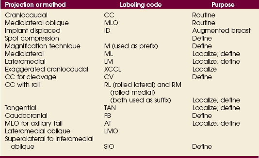
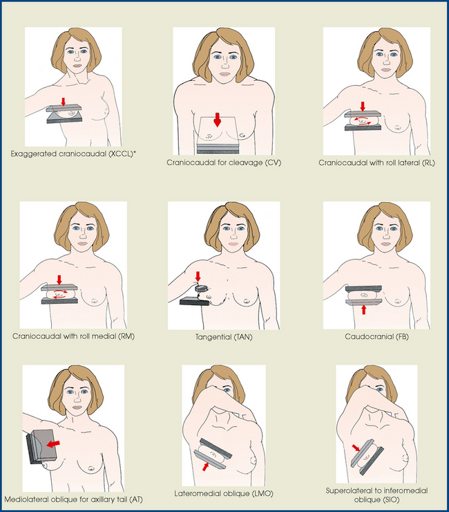
The routine projections are not always adequate in completely showing a patient’s breast tissue, or a specific area may require clearer delineation. Supplemental projections complement the routine projections and have distinct applications (Table 23-2). The mammographer should fully understand the value of each projection and its ability to show significant findings in the breast. This section provides a brief overview of significant mammographic findings in their most common radiographic presentation and provides suggested correlative supplemental projections. The language related to mammographic findings must be appreciated for the mammographer and the radiologist to work collaboratively toward a successful diagnostic examination.
TABLE 23-2
Supplemental projections or methods and their suggested applications
| Projection or method | Application |
| Spot compression | Defines lesion or area through focal compression; separates overlying parenchyma |
| Magnification (M) | Combines with spot compression to show margins of lesion; delineates microcalcifications |
| Mediolateral (ML) | Localization; shows air-fluid-fat levels; defines lesion located in lateral aspect of breast; complements mediolateral oblique (MLO) projection |
| Lateromedial (LM) | Localization; shows air-fluid-fat levels; defines lesion located in medial aspect of breast |
| Exaggerated craniocaudal (XCCL) | Visualizes lesions in deep outer aspect of breast that are not seen on standard CC |
| CC for cleavage (CV) | Visualizes deep medial breast tissue; shows medial lesion in true transverse or axial plane |
| CC with roll (RL, RM) | Triangulates lesion seen only on CC projection; defines location of lesion as in either superior or inferior aspect of breast |
| Tangential (TAN) | Confirms dermal vs. breast calcifications; shows obscure palpable lump over subcutaneous fat |
| Captured lesion (coat-hanger) | Shows palpable lump in posterior tissue that is difficult to immobilize with conventional techniques |
| Caudocranial (FB) | Visualizes superior breast tissue; defines lesion located in superior aspect of breast; replaces standard CC for patients with kyphosis or prominent pectoral muscles |
| MLO for axillary tail (AT) | Focal compression projection of AT |
| Lateromedial oblique (LMO) | Shows medial breast tissue; replaces standard MLO for patients with pectus excavatum, prominent pacemakers, prominent pectoral muscles, Hickman catheters, and postoperative open heart surgery |
| Superolateral to inferomedial oblique (SIO) | Visualizes upper-inner quadrant and lower-outer quadrant, which are normally superimposed on MLO and LMO projections |
The mass is the most common presentation of a potential abnormality in the breast. It is identified on two projections of the affected breast. A mass has a convex shape or an outward contour to its margins. If a suspected mass is identified on only one projection, the mammographer must strive to position the breast so that the area in question is shown on at least two projections. If the suspected mass is seen only on the MLO projection in the deep medial aspect of the breast, a CC projection for cleavage may complement the standard CC projection. Conversely, if the mass is seen in the extreme lateral aspect, an exaggerated craniocaudal (XCCL) projection laterally would be the projection of choice. In a sense, the radiographer is collecting evidence to prove whether the mass is real or merely a summation shadow of superimposed breast parenchyma. When a mass has been successfully identified on two projections, the radiologist describes the mass according to the following characteristics:
• Shape is a good predictor of the malignant or benign nature of the mass. Round, oval, or lobular masses are probably benign. Irregularly shaped masses are suspicious.
• Margin characteristics help predict whether a mass is malignant or benign. Well-defined circumscribed masses are probably benign. Microlobulated masses have a 50% chance of being malignant. Masses with obscured, ill-defined, indistinct margins are suspicious. Spiculated margins may indicate malignancy. Postbiopsy scarring may appear as a spiculated mass, and an accurate patient history revealing previous breast biopsies can prevent an unnecessary work-up (Fig. 23-28).
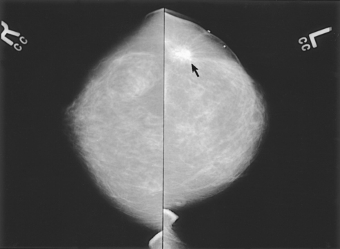
Fig. 23-28 Bilateral CC projections of a 55-year-old woman whose left breast was surgically altered as a result of previous breast cancer. Lumpectomy scar is visible on left breast (arrow). Surgical scars can mimic characteristics of breast cancer.
• The tissue density of the mass can predict whether it is malignant or benign. Masses consisting of mostly fat are usually benign, whereas masses consisting of variable fibroglandular tissue could be malignant.
• Although size cannot predict whether a lesion is malignant or benign, clinical management is the same regardless of size. The radiologist may request spot compression images to confirm mass characteristics. Magnification projections may be warranted if calcifications or spiculations are present within the mass. Ultrasonography may be appropriate to determine whether the mass is a simple cyst (Fig. 23-29).
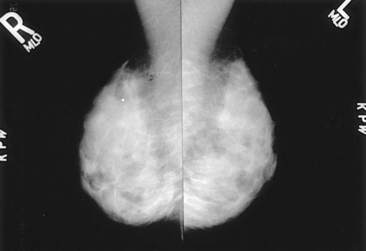
Fig. 23-29 Bilateral MLO projections of a 27-year-old woman who stopped breastfeeding 2 months before having this mammogram. Dense parenchyma with multinodularity throughout all quadrants is shown bilaterally. Lead marker in upper quadrant of the right breast marks a palpable mass; ultrasound examination proved the mass to be solid.
• The malignant or benign nature of a mass cannot be determined based on location. Most cancers are detected in the UOQ of the breast; however, most breast lesions—malignant or benign—are found in that quadrant. Cancer can occur in any region of the breast with a certain degree of probability. It is important to determine the location of a lesion for additional diagnostic procedures such as core biopsy or open surgical biopsy.
• Interval change may increase the suspicion of malignancy. The radiologist carefully compares current images with previous ones and notes whether the mass is newly apparent, an interval enlargement is present, the borders have become nodular or ill-defined, a mass has increased in density, or calcifications have appeared (Fig. 23-30).
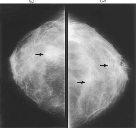
Fig. 23-30 CC projections of right and left breasts in a 28-year-old woman who is 4 months postpartum and not breastfeeding. Right breast contains a large mass (arrow) palpable on physical examination. Left breast contains two smaller nonpalpable masses (arrows) with microcalcifications. All three lesions were breast cancers.
• Almost all (98%) of the axillary lymph nodes are located in the UOQ. The nodes are well circumscribed, may have a central or peripheral area of fat, and can be kidney bean–shaped. If the lymph nodes appear normal, they are rarely mentioned in the context of an identifiable mass on the radiology report.
• Examples of benign stellate lesions include radial scar, fat necrosis, breast abscess, and sclerosing adenosis. Examples of benign circumscribed masses include fibroadenoma (Fig. 23-31), cyst, intramammary lymph node, hematoma, and galactocele.
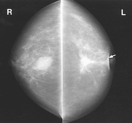
Fig. 23-31 CC projections of bilateral breast masses. Left breast (L) contains irregular carcinoma that is producing considerable spiculation, nipple retraction (arrow), and skin thickening. Right breast (R) contains fibroadenoma.
• A density is seen on only one projection, is not confirmed three-dimensionally, may represent superimposed structures, and may have scalloped edges or concave borders or both. The radiologist may request spot compression projections, rolled projections, or angled projections to confirm or rule out the presence of a real density. A suspicious density seen on only one projection within the breast is usually a summation shadow of superimposed breast parenchyma and disappears when the breast tissue is spread apart.
• Calcifications are often normal metabolic occurrences within the breast and are usually benign (Fig. 23-32). Approximately 15% to 25% of microcalcifications found in asymptomatic women are associated with cancer, however. These calcifications can have definitive characteristics. Because of size, some microcalcifications are more difficult to interpret. The most valuable tool for defining microcalcifications is a properly performed image using magnification technique. Using this image, the radiologist can determine better whether the calcifications are suspicious and warrant any further work-up.
• Benign calcifications may have one or more of the following attributes: moderate size, scattered location, round shape, and, usually, bilateral occurrence. In addition, they may be eggshell (lucent center), arterial (parallel tracks), crescent, or sedimented (“teacup” milk of calcium). Calcifications may also represent a fibroadenoma (“popcorn”) and postsurgical scarring (sheets or large strands of calcium). The projection suggested for better defining sedimented milk of calcium is the 90-degree lateral projection—lateromedial (LM) or mediolateral (ML). If possible, the mammographer should select the lateral projection that places the suspected area closest to the IR. The 90-degree lateral is also used as a triangulation projection before needle localization and to show air-fluid-fat levels.
• Suspicious calcifications are small (occurring in groups of five or more), located within the breast parenchyma (vs. dermal), localized in distribution, and branching and linear in shape (Fig. 23-33). Dermal or skin calcifications can mimic suspicious microcalcifications within the breast parenchyma. The tangential (TAN) projection is best suited for resolving this discrepancy.
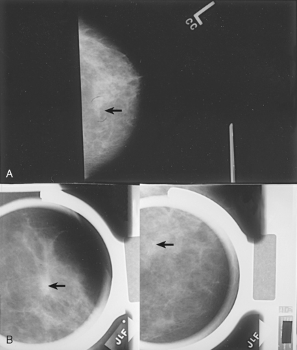
Fig. 23-33 Microcalcifications are an early sign of breast cancer. A, Mass with calcifications (arrow). B, This type of mass is best visualized with two right-angle projections (arrows).
• Other supplemental projections are intended to offer alternative methods for tailoring the mammographic procedure to the specific abilities of the patient and the requirements of the interpreting physician. Often the need for additional projections is determined only after careful examination of the standard projections, however. Throughout mammographic procedures, the radiographer should consistently evaluate the images, keeping foremost in mind the optimal demonstration of possible findings. The mammographer may develop the expertise to predict and perform supplemental projections that confirm or rule out suspected breast abnormalities. As with all radiographic procedures, image evaluation is a crucial component of high-quality imaging systems. In doing so, the mammographer becomes an integral member of the breast imaging team, actively participating in the work-up of a symptomatic patient.
Image Enhancement Methods
The spot compression technique and the magnification technique are designed to enhance the image of the area under investigation.
MAGNIFICATION TECHNIQUE (M USED AS PREFIX)
• Attach the firm, radiolucent magnification platform designed by the equipment manufacturer to the unit. The patient’s breast is positioned on the platform between the compression device and a nongrid IR.
• Select the smallest focal spot target size (≤0.1 mm is preferred). Most units allow magnification images to be exposed only using the correct focal spot size.
• Select the appropriate compression paddle (regular, quadrant, or spot compression). Collimate according to the size of the compression paddle.
• Reposition the patient’s breast to obtain the projection that best shows the area of interest. The angle of the C-arm can be adjusted to accommodate any projection normally performed using a traditional grid technique.
• When full compression is achieved, move the AEC detector to the appropriate position and instruct the patient to stop breathing (Fig. 23-34).
Structures shown: This technique magnifies the area of interest with improved detail, facilitating determination of the characteristics of microcalcifications (Fig. 23-35) and the margins (or lack of definitive margins) of suspected lesions (Fig. 23-36).
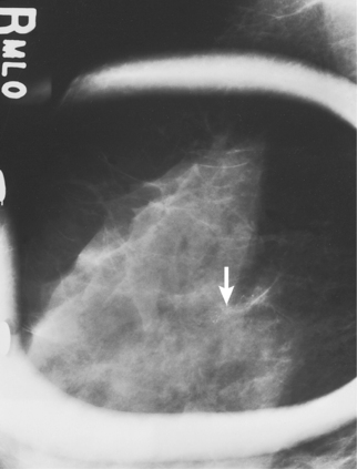
Fig. 23-35 Spot compression used with magnification in MLO projection, showing microcalcifications (arrow).
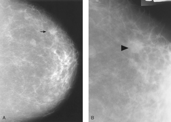
Fig. 23-36 A, CC projection showing possible lesion in right breast (arrow). B, Image with 2× magnification in the same patient, convincingly showing a lesion with irregular margin (arrowhead).
SPOT COMPRESSION TECHNIQUE
In conjunction with magnification technique:
• Place a firm, radiolucent magnification platform designed for use with the dedicated mammography equipment on the unit, between the patient’s breast and a nongrid image receptor (see p. 417).
• Select the smallest focal spot target size (≤0.1 mm is preferred).
For palpable masses: A TAN projection combined with spot compression and the magnification technique is most often used to image a palpable mass; however, the spot compression technique in a previously imaged projection is also requested by many radiologists.
• Select the appropriate spot compression device.
• Reposition the patient’s breast to obtain the projection that best shows the suspected abnormality.
• Mark the location of the palpable mass with a felt-tip pen.
• Center the area of interest under the compression device.
• Inform the patient that compression of the breast will be used. Bring the compression paddle into contact with the breast, and slowly apply compression until the breast feels taut.
• Instruct the patient to indicate whether the compression becomes uncomfortable.
• When full compression is achieved, move the AEC detector to the appropriate position and instruct the patient to stop breathing (Fig. 23-37).
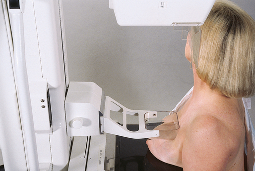
• While viewing the routine mammogram, measure the location of the area of interest from a reference point (the nipple), using either a tape measure or the fingertips.
• Select the appropriate spot compression device.
• Reposition the patient’s breast to obtain the projection from which the measurements were taken.
• Using the same reference point, transfer the measurements taken from the mammogram onto the patient.
• Mark the area of interest with a felt-tip pen.
• Center the area of interest under the compression device.
• Inform the patient that compression of the breast will be used. Bring the compression paddle into contact with the breast, and slowly apply compression until the breast feels taut.
• Instruct the patient to indicate whether the compression becomes uncomfortable.
• When full compression is achieved, move the AEC detector to the appropriate position, and instruct the patient to stop breathing.
Structures shown: The spot compression technique resolves superimposed structures seen on only one projection, better visualizes small lesions located in the extreme posterior breast, separates superimposed ductal structures in the subareolar region, and improves visualization in areas of dense tissue through localized compression (Fig. 23-38).
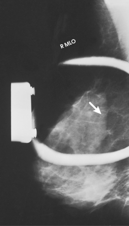
Fig. 23-38 Spot compression of suspicious area containing microcalcifications (arrow). Lesion was later biopsied and was found to be ductal carcinoma in situ, an early stage of cancer.
The following should be clearly shown:
Area of interest clearly seen within compressed margins
Close collimation to the area of interest unless contraindicated by radiologist
Improved recorded detail through the use of close collimation and magnification technique employing a spot compression device
NOTE: Densities caused by the superimposition of normal breast parenchyma disappear on spot compression images.
Supplemental Projections
Supplemental projections described in the following section include the 90-degree ML projection, the CC projection for cleavage, and others. These projections are designed to delineate areas not visualized or not clearly seen on the routine projections.
90-DEGREE MEDIOLATERAL (ML) PROJECTION
• Rotate the C-arm assembly 90 degrees, with the x-ray tube placed on the medial side of the patient’s breast.
• Have the patient bend slightly forward. Position the superior corner of the image receptor high into the axilla, with the patient’s elbow flexed and the affected arm resting behind the image receptor.
• Ask the patient to relax the affected shoulder.
• Pull the breast tissue and pectoral muscle superiorly and anteriorly, ensuring that the lateral rib margin is pressed firmly against the edge of the image receptor.
• Rotate the patient slightly laterally to help bring the medial tissue forward.
• Gently pull the medial breast tissue forward from the sternum, and position the nipple in profile.
• Hold the patient’s breast up and out by rotating the hand so that the base of the thumb and the heel of the hand support the breast.
• Inform the patient that compression of the breast will be used. Continue to hold the patient’s breast up and out while sliding the hand toward the nipple as the compression paddle is brought into contact with the breast. Do not allow the breast to droop (Fig. 23-39).
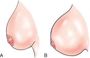
Fig. 23-39 A, Lateral profile of breast showing inadequate compression and drooping breast. B, Lateral profile of properly compressed breast. Note how compression has overcome the effect of gravity and how the breast is spread out over a greater area.
• Slowly apply compression until the breast feels taut.
• Instruct the patient to indicate whether compression becomes uncomfortable.
• Ask the patient to hold the opposite breast away from the path of the beam.
• When full compression is achieved, move the AEC detector to the appropriate position, and instruct the patient to stop breathing (Fig. 23-40).
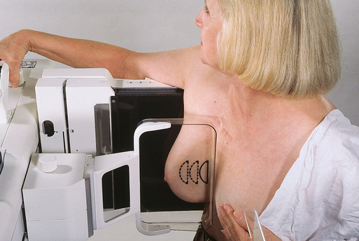
Structures shown: This projection shows lesions on the lateral aspect of the breast in the superior or inferior aspects. It resolves superimposed structures seen on the MLO projection, localizes a lesion seen on one (or both) of the initial projections, and shows air-fluid and fat-fluid levels in breast structures (i.e., milk of calcium, galactoceles) and in pneumocystography.
The following should be clearly shown:
Deep and superficial breast tissues well separated when breast is adequately maneuvered up and out from chest wall (Figs. 23-41 and 23-42)

Fig. 23-41 ML projection is often used as preliminary projection in breast localization procedure. Arrow denotes lesion.

Retroglandular fat well visualized to ensure inclusion of deep fibroglandular breast tissue
90-DEGREE LATEROMEDIAL (LM) PROJECTION
• Rotate the C-arm assembly 90 degrees, with the x-ray tube placed on the lateral side of the patient’s breast.
• Position the superior corner of the image receptor at the level of the jugular notch.
• Have the patient flex the neck slightly forward.
• Have the patient relax the affected shoulder, flex the elbow, and rest the affected arm over the top of the image receptor.
• Pull the breast tissue and pectoral muscle superiorly and anteriorly, ensuring that the patient’s sternum is pressed firmly against the edge of the image receptor.
• Rotate the patient slightly medially to help bring the lateral tissue forward.
• Have the patient rest the chin on the top edge of the image receptor to help loosen the skin in the medial aspect of the breast.
• Position the nipple in profile.
• Hold the patient’s breast up and out. Do not let it droop.
• Inform the patient that compression of the breast will be used. Bring the compression paddle past the latissimus dorsi muscle and into contact with the breast. Slowly apply compression while sliding the hand out toward the nipple until the patient’s breast feels taut.
• Instruct the patient to indicate whether the compression becomes uncomfortable.
• When full compression is achieved, move the AEC detector to the appropriate position, and instruct the patient to stop breathing (Fig. 23-43).
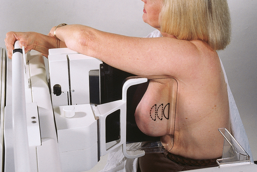
Structures shown: This projection shows lesions on the medial aspect of the breast in the superior or inferior aspects (Fig. 23-44). It resolves superimposed structures seen on the MLO projection, localizes a lesion seen on one (or both) of the initial projections, and shows air-fluid and fat-fluid levels in breast structures (i.e., milk of calcium, galactoceles) and in pneumocystography.
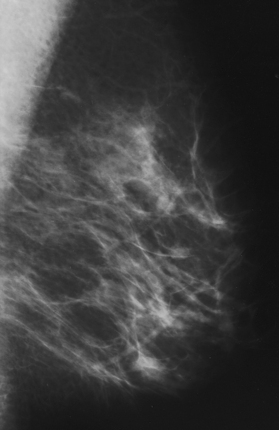
EXAGGERATED CRANIOCAUDAL (XCCL) PROJECTION
• Elevate the inframammary fold to its maximal height.
• Adjust the height of the C-arm accordingly.
• Use both hands to pull the breast gently onto the image receptor while instructing the patient to press the thorax against the breast tray.
• Slightly rotate the patient medially to place the lateral aspect of the breast on the image receptor.
• Place an arm against the patient’s back with the hand on the shoulder of the affected side, ensuring that the shoulder is relaxed in external rotation.
• Slightly rotate the patient’s head away from the affected side.
• Have the patient lean toward the machine and rest the head against the face guard.
• Rotate the C-arm assembly mediolaterally 5 degrees to eliminate overlapping of the humeral head.
• Inform the patient that compression of the breast will be used. Smooth and flatten the breast tissue toward the nipple while bringing the compression paddle into contact with the breast.
• Slowly apply compression until the breast feels taut.
• Instruct the patient to indicate whether the compression becomes uncomfortable.
• When full compression is achieved, move the AEC detector to the appropriate position, and instruct the patient to stop breathing (Figs. 23-45 and 23-46).
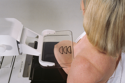
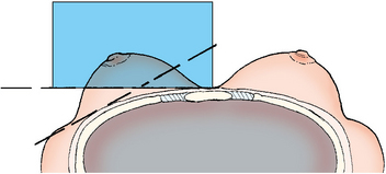
Structures shown: This projection shows a superoinferior projection of the lateral fibroglandular breast tissue and posterior aspect of the pectoral muscle. It also shows a sagittal orientation of a lateral lesion located in the AT of the breast.
The following should be clearly shown:
Retroglandular fat well visualized to ensure inclusion of deep fibroglandular breast tissue on lateral aspect of breast and lower axillary region
Pectoral muscle visualized over lateral chest wall (Fig. 23-47)
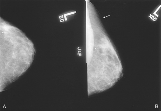
Fig. 23-47 A, CC projection of left breast. B, XCCL projection. This projection is exaggerated laterally to show AT (arrow). Note also visualization of pectoral muscle.
Humeral head projected clear of image with use of a 5-degree ML angle
CRANIOCAUDAL PROJECTION FOR CLEAVAGE (CV)
• Turn the AEC off, and preselect a manual technique. The radiographer may use AEC only if enough breast tissue is positioned over the AEC detector. The cleavage may be intentionally offset for this purpose.
• Determine the proper height of the breast tray by elevating the inframammary fold to its maximal height.
• Adjust the height of the C-arm accordingly.
• Standing behind the patient, use both hands to lift and pull both breasts gently forward onto the image receptor while instructing the patient to press the thorax against the image receptor.
• Pull as much medial breast tissue as possible onto the image receptor.
• Slightly rotate the patient’s head away from the affected side.
• Have the patient lean toward the machine and rest the head against the face guard.
• Ask the patient to hold the grip bars with both hands to keep in position on the image receptor.
• Place one hand at the level of the patient’s jugular notch, and then slide the hand down the patient’s chest while pulling down as much deep medial tissue as possible.
• Inform the patient that compression of the breast will be used. Bring the compression paddle into contact with the breasts, and slowly apply compression until the breast feels taut. Using a quadrant compression paddle allows better compression of the cleavage area and allows more of the area of interest to be pulled into the imaging area. If a quadrant paddle is used, collimate to the area of compression to visualize the detail of the tissue better.
• Instruct the patient to indicate when the compression becomes uncomfortable.
• When full compression is achieved, move the AEC detector to the appropriate position if AEC is used, and instruct the patient to stop breathing (Fig. 23-48).
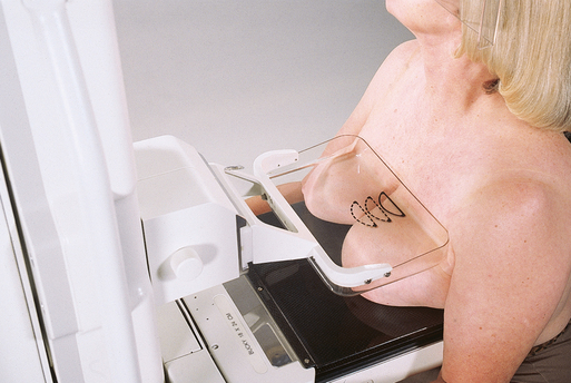
Structures shown: This projection shows lesions located in the deep posteromedial aspect of the breast.
The following should be clearly shown:
Area of interest over the central portion of the image receptor (over the AEC detector if possible) with cleavage slightly off-centered or with cleavage centered to the image receptor and manual technique selected (Fig. 23-49)
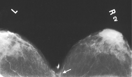
Fig. 23-49 CV showing benign calcifications located in deep medial tissue (arrow). With centered cleavage, the manual technique should be selected.
Deep medial tissue of affected breast
All medial tissue included, as shown by the visualization of medial retroglandular fat and the absence of any fibroglandular tissue extending to posteromedial edge of imaged breasts
Uniform tissue exposure if compression is adequate. (Retroareolar regions may not be adequately compressed because of emphasis on the deep medial tissue. It is not necessary to image all of the breast tissue on this projection.)
CRANIOCAUDAL PROJECTION WITH ROLL LATERAL OR ROLL MEDIAL (RL OR RM USED AS SUFFIX)
• Reposition the patient’s breast in the projection that best shows the suspected superimposition (usually the CC projection).
• Place the hands on opposite surfaces of the patient’s breast (superior/inferior), and roll the surfaces in opposite directions. The direction of the roll is not important as long as the mammographer rolls the superior surface in one direction and the inferior surface in the other direction. In a sense, the mammographer is very gently rotating the breast approximately 10 to 15 degrees (Fig. 23-50).
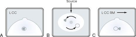
Fig. 23-50 A, CC projection showing lesion that may represent superimposition of two structures. If spot compression fails to resolve these structures, CC projection with the roll position may be performed. B, Anterior view of CC projection, with arrows indicating rolling of superior and inferior breast surfaces in opposite directions to separate superimposed structures. C, CC projection with RM, showing resolution of two lesions. Arrow indicates direction of roll of superior surface of breast.
• Place the patient’s breast onto the image receptor surface with the lower hand while holding the rolled position with the upper hand.
• Note the direction of the superior surface roll (lateral or medial), and label the image accordingly. If the superior aspect of the breast is rolled medially, the image should be labeled RM.
• Inform the patient that compression of the breast will be used. Bring the compression paddle into contact with the breast, and slide the hand out while rolling the breast tissue.
• Slowly apply compression until the breast feels taut.
• Instruct the patient to indicate whether the compression becomes uncomfortable.
• When full compression is achieved, move the AEC detector to the appropriate position and instruct the patient to stop breathing (Fig. 23-51).
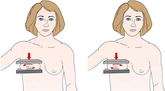
• Perpendicular to the base of the breast
• Alternatively, the standard CC projection may be performed with the C-arm assembly rotated 10 to 15 degrees either mediolaterally or lateromedially to eliminate superimposition of breast tissue. This is often the preferred method because it allows easier duplication of the projection during subsequent examinations.
Structures shown: This position shows separation of superimposed breast tissues (also known as summation shadow), particularly those seen only on the CC projection. The position also helps determine whether a lesion is located in the superior or inferior aspect of the breast (Fig. 23-52).
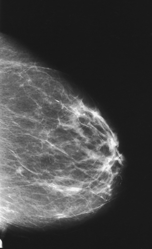
The following should be clearly shown:
Suspected superimposition adequately resolved
Suspected lesion in either superior or inferior aspect of breast
PNL extending posteriorly to edge of image, measuring within ⅓ inch (1 cm) of the depth of PNL on MLO projection
All medial tissue included, as shown by the visualization of medial retroglandular fat and the absence of fibroglandular tissue extending to posteromedial edge of image
Nipple in profile and at midline, indicating no exaggeration of positioning. The nipple is used as a point of reference to distinguish the location of the suspected lesion, if it exists.
Some lateral tissue possibly excluded to emphasize medial tissue visualized
Slight medial skin reflection at cleavage, ensuring that posterior medial tissue is adequately included
TANGENTIAL (TAN) PROJECTION
For a palpable mass: The TAN projection is most often performed with use of the magnification technique.
• Select a standard, quadrant, or spot compression paddle.
• Locate the area of interest by palpating the patient’s breast.
• Place a radiopaque marker or BB on the mass.
• Using the imaginary line between the nipple and the BB as the angle reference (Fig. 23-53), rotate the C-arm apparatus until the central ray is directed tangential to the breast at the point identified by the BB marker (the “shadow” of the BB is projected onto the image receptor surface).
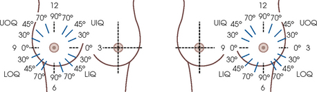
Fig. 23-53 Degree of angle for TAN projection. Correlation of location of abnormality with degree of rotation of C-arm; an angle of the C-arm shows upper quadrant and lower quadrant abnormality tangentially.
• Using the appropriate compression paddle (regular or spot compression), compress the breast and skin area while ensuring that enough breast tissue covers the AEC detector area.
• Slowly apply compression until the breast feels taut.
• Instruct the patient to indicate whether the compression becomes uncomfortable.
• When full compression is achieved, move the AEC detector to the appropriate position, and instruct the patient to stop breathing (Figs. 23-54 and 23-55).
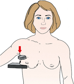
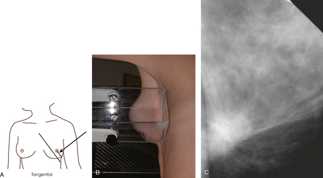
For skin localization or nonpalpable dermal calcifications, two projections are necessary: (1) a localization projection (which depends on the area of interest) and (2) a TAN projection.
• From the routine CC and MLO projections, determine the quadrant in which the area of interest is located.
• Determine which projection would best localize the area of interest—the CC or 90-degree lateral projection.
• Turn off the automatic compression release, and inform the patient that compression will be continued while the first image is processed.
• Using a localization compression paddle, position the C-arm and breast so that the paddle opening is positioned over the quadrant of interest.
• Slowly apply compression until the breast feels taut.
• Instruct the patient to indicate whether the compression becomes uncomfortable.
• When full compression is achieved, move the AEC detector to the appropriate position, and instruct the patient to stop breathing.
• Do not release compression. Keep the breast compressed while the initial image is processed.
• Check the initial image, and locate the area of interest using the alphanumeric identifiers.
• With the patient’s breast still under compression, locate the corresponding area on the breast and place a radiopaque marker or BB over the area.
• Release breast compression, and replace the localization compression paddle with a regular or spot compression paddle.
• Rotate the C-arm apparatus until the central ray is directed tangential to the breast at the point identified by the BB marker (the “shadow” of the BB is projected onto the image receptor surface).
• Compress the area while ensuring that enough breast tissue covers the AEC detector area.
• Slowly apply compression until the breast feels taut.
• Instruct the patient to indicate whether the compression becomes uncomfortable.
• When full compression is achieved, move the AEC detector to the appropriate position, and instruct the patient to stop breathing.
Structures shown: This projection shows superficial lesions close to the skin surface with minimal parenchymal overlapping. It also shows skin calcifications or palpable lesions projected over subcutaneous fat (Fig. 23-56).
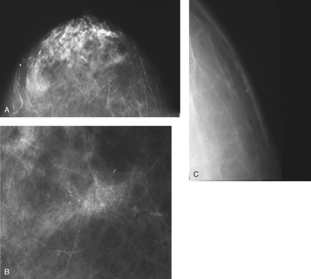
Fig. 23-56 A, Left CC projection reveals area of suspicious-appearing calcifications. B, Magnified CC projection. C, TAN magnification projection with spot compression of localized area showing benign dermal calcifications.
CAPTURED LESION OR COAT-HANGER PROJECTION
This specialized positioning is seldom used but is very useful when imaging a palpable lesion located in the extreme posterior breast tissue. Sometimes lesions in this area tether themselves to the chest wall and resist being pulled forward to be visualized on a routine projection. This procedure is a variation of the TAN projection and should be labeled as such. It is generally performed using magnification and tight collimation. The captured lesion or coat-hanger projection captures and isolates the palpable lump for imaging (Fig. 23-57).
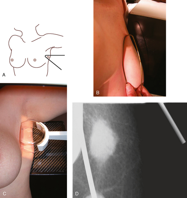
Fig. 23-57 Coat-hanger projection. A and B, A slippery lesion is captured for imaging by the angle of a wire coat-hanger. C, Inverted spot compression device can sometimes achieve the same results. D, Radiograph of lesion imaged using coat-hanger projection. This lesion could not be viewed on routine projections because of its position within the breast and the elastic nature of the lesion.
• Place the magnification platform designed for use with the dedicated mammography unit on the equipment. If using a coat-hanger for positioning, remove the compression paddle. Otherwise, insert the spot compression paddle upside down. The chest wall edge of the compression device is used to hold the mass in place.
• Place a lead BB over the palpable mass.
• Using your hands, determine the projection most likely to image the lump with no superimposition of other tissue. Place the area of clinical concern at the edge of the breast in a tangent plane to the film.
• The palpable area of clinical concern is captured with a corner of a wire coat-hanger or an inverted spot compression device. No additional compression is needed.
• It may be necessary to use a manual technique if the amount of tissue captured within the coat-hanger or inverted compression device does not cover the AEC detector.
CAUDOCRANIAL (FB) PROJECTION
• Rotate the C-arm apparatus 180 degrees from the rotation used for a routine CC projection.
• Standing on the medial side of the breast to be imaged, elevate the inframammary fold to its maximal height.
• Adjust the height of the C-arm so that it is in contact with the superior breast tissue.
• Lean the patient slightly forward while gently pulling the elevated breast out and perpendicular to the chest wall. Hold the breast in position.
• Have the patient rest the affected arm over the top of the image receptor.
• Inform the patient that compression of the breast will be used. Bring the compression paddle from below into contact with the patient’s breast while sliding the hand toward the nipple.
• Slowly apply compression until the breast feels taut.
• Instruct the patient to indicate whether the compression becomes uncomfortable.
• To ensure that the patient’s abdomen is not superimposed over the path of the beam, have the patient pull in the abdomen or move the hips back slightly.
• When full compression is achieved, move the AEC detector to the appropriate position, and instruct the patient to stop breathing (Fig. 23-58).
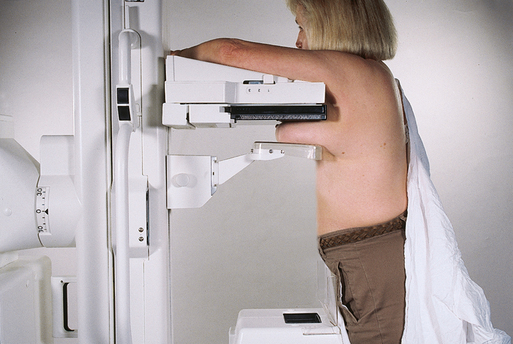
Structures shown: This projection shows an inferosuperior projection of the breast for the improved visualization of lesions located in the superior aspect as a result of reduced object–to–image receptor distance. The FB projection may also facilitate a shorter route for needle-wire insertion to localize an inferior lesion (Figs. 23-59 and 23-60). The projection is also used as a replacement for the standard CC projection in patients with prominent pectoral muscles or kyphosis.
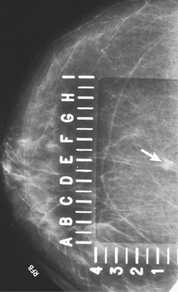
Fig. 23-59 FB projection performed in a 57-year-old woman to facilitate shortest route for localizing lesion identified in inferior aspect of breast (arrow).
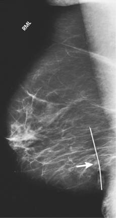
Fig. 23-60 Orthogonal 90-degree ML projection of the patient in Fig. 23-58, showing successful placement of needle-wire system within lesion (arrow). The lesion was found to be a 9-mm infiltrating ductal carcinoma.
The following should be clearly shown:
Superior breast tissue and lesions clearly visualized
For needle localization images, inferior lesion visualized within specialized fenestrated compression plate
Patient’s abdomen projected clear of image
Inclusion of fixed posterior tissue of superior aspect of breast
PNL extending posteriorly to edge of image, measuring within ⅓ inch (1 cm) of depth of PNL on MLO projection
All medial tissue included as shown by visualization of medial retroglandular fat and absence of fibroglandular tissue extending to posteromedial edge of image
Nipple in profile, if possible, and at midline, indicating no exaggeration of positioning
Some lateral tissue possibly excluded to emphasize medial tissue
Slight medial skin reflection at cleavage, ensuring that posterior medial tissue is adequately included
MEDIOLATERAL OBLIQUE PROJECTION FOR AXILLARY TAIL (AT)
• Determine the degree of obliquity of the C-arm apparatus by rotating the tube until the long edge of the image receptor is parallel with the AT of the affected side. The degree of obliquity varies between 10 degrees and 45 degrees.
• Adjust the height of the C-arm so that the superior border of the image receptor is just under the axilla.
• Instruct the patient to elevate the arm of the affected side over the corner of the image receptor and to rest the hand on the adjacent handgrip. The patient’s elbow should be flexed.
• Have the patient relax the affected shoulder and lean it slightly anterior. Using the flat surface of the hand, gently pull the tail of the breast anteriorly and medially onto the image receptor, keeping the skin and tissue smooth and free of wrinkles.
• Ask the patient to turn the head away from the side being examined and to rest the head against the face guard.
• Inform the patient that compression of the breast will be used. Continue to hold the breast in position while sliding the hand toward the nipple as the compression paddle is brought into contact with the AT (Fig. 23-61).
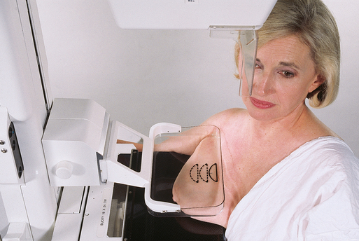
• Slowly apply compression until the breast feels taut. The corner of the compression paddle should be inferior to the clavicle. To avoid patient discomfort caused by the corner of the paddle and to facilitate even compression, remind the patient to keep the shoulder relaxed.
• Instruct the patient to indicate whether the compression becomes uncomfortable.
• When full compression is achieved, move the AEC detector to the appropriate position, and instruct the patient to stop breathing. It may be necessary to increase exposure factors if compression is not as taut as in the routine projections.
Structures shown: This projection shows the AT of the breast, with emphasis on its lateral aspect.
The following should be clearly shown:
AT with inclusion of axillary lymph nodes under focal compression (Fig. 23-62)
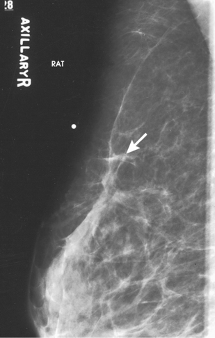
Fig. 23-62 MLO projection for AT of a 68-year-old woman, showing ill-defined stellate mass measuring 8 mm (arrow). Biopsy confirmed lesion to be infiltrating ductal carcinoma.
Uniform tissue exposure if compression is adequate
Slight skin reflection of affected arm on superior border of image
LATEROMEDIAL OBLIQUE (LMO) PROJECTION
• Determine the degree of obliquity of the C-arm apparatus by rotating the assembly until the long edge of the image receptor is parallel with the upper third of the pectoral muscle of the affected side. The central ray enters the inferior aspect of the breast from the lateral side. The degree of obliquity should be between 30 degrees and 60 degrees, depending on the body habitus of the patient.
• Adjust the height of the C-arm so that the superior border of the image receptor is level with the jugular notch.
• Ask the patient to place the opposite hand on the C-arm. The patient’s elbow should be flexed.
• Lean the patient toward the C-arm apparatus, and press the sternum against the edge of the image receptor, which is slightly off-center toward the opposite breast.
• Have the patient relax the affected shoulder and lean it slightly anterior. Gently pull the patient’s breast and pectoral muscle anteriorly and medially with the flat surface of the hand positioned along the lateral aspect of the breast.
• Scoop breast tissue up with the hand, gently grasping the breast between fingers and thumb.
• Center the breast with the nipple in profile, if possible, and hold the breast in position.
• Inform the patient that compression of the breast will be used. Continue to hold the patient’s breast up and out while sliding the hand toward the nipple as the compression paddle is brought into contact with the LOQ of the breast.
• Slowly apply compression until the breast feels taut.
• Instruct the patient to indicate whether the compression becomes uncomfortable.
• Pull down on the patient’s abdominal tissue to open the inframammary fold.
• Ask the patient to rest the affected elbow on the top edge of the image receptor.
• When full compression is achieved, move the AEC detector to the appropriate position, and instruct the patient to stop breathing (Fig. 23-63).
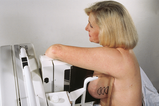
• Perpendicular to the image receptor
• The C-arm apparatus is positioned at an angle determined by the slope of the patient’s pectoral muscle (30 to 60 degrees). The actual angle is determined by the patient’s body habitus: Tall, thin patients require steep angulation, whereas short, stout patients require shallow angulation.
Structures shown: This projection shows a true reverse projection of the routine MLO projection and is typically performed to show the medial breast tissue better. It is also performed if the routine MLO cannot be completed because of one or more of the following conditions: pectus excavatum, post open-heart surgery, prominent pacemaker, men or women with prominent pectoralis muscles, or Port-A-Cath (Hickman catheters).
The following should be clearly shown:
Medial breast tissue clearly visualized (Fig. 23-64)
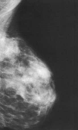
PNL measuring within ⅓ inch (1 cm) of the depth of the PNL on the CC projection. (While drawing the PNL obliquely, following the orientation of the breast tissue toward the pectoral muscle, measure its depth from nipple to pectoral muscle or to the edge of the image, whichever comes first.)
Inferior aspect of the pectoral muscle extending to nipple line or below it if possible
Pectoral muscle with anterior convexity to ensure a relaxed shoulder and axilla
Deep and superficial breast tissues well separated when breast is adequately maneuvered up and out from chest wall
Retroglandular fat well visualized to ensure inclusion of deep fibroglandular breast tissue
SUPEROLATERAL TO INFEROMEDIAL OBLIQUE (SIO) PROJECTION
• Rotate the C-arm apparatus so that the central ray is directed at an angle to enter the superior and lateral aspect of the affected breast. The LIQ is adjacent to the image receptor.
• Adjust the degree of C-arm obliquity according to the body habitus of the patient, or, when the SIO projection is being used as an additional projection to image an area of the tissue more clearly without superimposition of surrounding tissue, adjust the C-arm to the degree of angulation required by the radiologist, generally a 20- to 30-degree angle.
• Adjust the height of the C-arm to position the patient’s breast over the center of the image receptor.
• Instruct the patient to rest the hand of the affected side on the handgrip adjacent to the image receptor holder. The patient’s elbow should be flexed. For shallow-angled SIO projections, the arm on the affected side should lie straight against the patient’s side. The handgrip is held by the hand on the contralateral side.
• Place the upper corner of the image receptor along the sternal edge adjacent to the upper inner aspect of the patient’s breast.
• With the patient leaning slightly forward, gently pull as much medial tissue as possible away from the sternal edge while holding the breast up and out. The breast should not droop. Ensure that the patient’s back remains straight during positioning and that the patient does not lean to the side or toward the image receptor.
• Inform the patient that compression of the breast will be used. Continue to hold the breast up and out.
• Bring the compression paddle under the affected arm and into contact with the patient’s breast while sliding the hand toward the patient’s nipple. For shallow-angled SIO, the affected arm at the patient’s side should be bent at the elbow to avoid superimposition of the humeral head over the breast tissue.
• Slowly apply compression until the breast feels taut. The upper corner of the compression paddle should be in the axilla for the standard SIO projection.
• Instruct the patient to indicate whether the compression becomes uncomfortable.
• When full compression is achieved on the standard SIO, help the patient bring the arm up and over with the flexed elbow resting on top of the image receptor.
• Gently pull down on the patient’s abdominal tissue to smooth out any skin folds.
• Move the AEC detector to the appropriate position, and instruct the patient to stop breathing (Fig. 23-65).
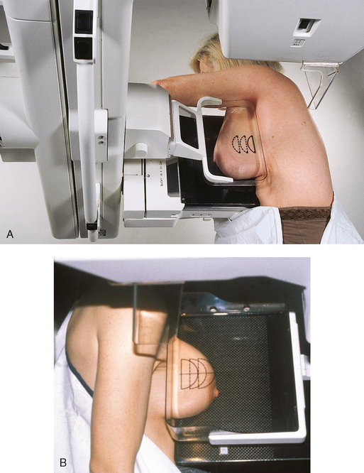
Structures shown: This projection shows the UIQ and LOQ of the breast free of superimposition. In addition, lesions located in the lower inner aspect of the breast are shown with better recorded detail. This projection may also be used to replace the MLO ID projection in patients with encapsulated implants (Fig. 23-66).
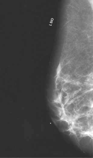
The following should be clearly shown:
UIQ and LOQ free of superimposition (these quadrants are superimposed on the MLO and the LMO projections)
Lower inner aspect of breast visualized with greater detail
Deep and superficial breast tissues well separated when breast is adequately maneuvered up and out from chest wall
Retroglandular fat well visualized to ensure inclusion of deep fibroglandular breast tissue
Localization of Nonpalpable Lesions
When mammography identifies a nonpalpable lesion that warrants biopsy, the abnormality must be accurately located so that the smallest amount of breast tissue is removed for microscopic evaluation, minimizing trauma to the breast. This technique conserves the maximal amount of normal breast tissue unless extensive surgery is indicated.
Nonpalpable breast lesions can be localized using three techniques: (1) needle-wire localization for open surgical biopsy, (2) FNAB, and (3) large-core needle biopsy (LCNB). Needle-wire localization uses a needle that contains a hooked guidewire to lead the surgeon directly to the suspicious tissue. All three methods use images to triangulate the location of the lesion to be biopsied. FNAB uses a hollow small-gauge needle to extract tissue cells from a suspicious lesion. FNAB can potentially decrease the need for surgical excisional biopsy by identifying benign lesions and by diagnosing malignant lesions that require extensive surgery rather than excisional biopsy.
LCNB obtains small samples of breast tissue by means of a 9-gauge, 11-gauge, or 14-gauge needle with a trough adjacent to the tip of the needle. A vacuum suction system is frequently employed during this procedure to pull the target tissue into a collecting chamber. Because larger tissue samples are obtained with LCNB, and results are very accurate, clinical support exists for using this technique instead of surgical excisional biopsy to diagnose pathology of a lesion. LCNB may be used with clinical, ultrasound, stereotactic, and MRI guidance. The method used depends on the preference of the radiologist and the surgeon and is typically determined by the modality in which the lesion is most visible.
Needle-wire localization is a predominant method for localizing nonpalpable lesions for open surgical biopsy. The four most common needle-wire localization systems are the Kopans, Homer (18-gauge), Frank (21-gauge), and Hawkins (20-gauge) biopsy guides. With each system, a long needle containing a hooked wire is inserted into the breast so that the tip approximates the lesion. A small incision (1 to 2 mm) at the entry site may be necessary to facilitate insertion of a larger gauge needle. When the wire is in place, the needle is withdrawn over the wire (Fig. 23-67). The hook on the end of the wire anchors the wire within the breast tissue. The surgeon cuts along the guidewire and removes the breast tissue around the wire’s hooked end. Alternatively, the surgeon may choose an incision site that intercepts the anchored wire distant from the point of wire entry. Some radiologists also inject a small of amount of methylene blue dye to label the proper biopsy site visually. After needle-wire localization, the patient is properly bandaged and taken to the surgical area for excisional biopsy (Fig. 23-68). Ideally, the radiologist and surgeon should review the localization images together before the excisional biopsy.
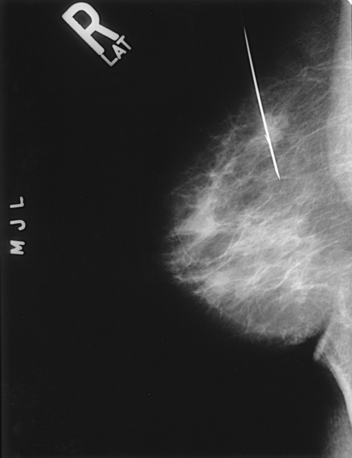
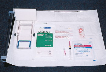
Fig. 23-68 Material for breast localization using specialized compression plate: alphanumeric localization compression plate, sterile gloves, topical antiseptic, alcohol wipe, local anesthetic, 5-mL syringe, 25-gauge needle, scalpel blade, sterile gauze, tape, and needle-wire localization system.
BREAST LESION LOCALIZATION WITH A SPECIALIZED COMPRESSION PLATE
Many mammography units have a specialized compression plate with an opening that can be positioned over a breast lesion. Through this opening, a localizing needle-wire can be introduced into the breast. The initial mammogram and a 90-degree lateral projection are usually reviewed together to determine the shortest distance from the skin to the breast lesion. A lesion in the inferior aspect of the breast may be best approached from the medial, lateral, or inferior surface of the breast but not from the superior surface.
The opening in the specialized fenestrated compression plate may consist of a rectangular cutout with radiopaque alphanumeric grid markings along at least two adjacent sides. Alternatively, the plate may contain several rows of holes, each large enough to accommodate the insertion of a localization needle (Fig. 23-69).
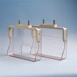
Needle-localization procedures vary from radiologist to radiologist. As a result, no standardized procedure exists. The following steps are typically taken:
• Perform preliminary routine full-breast projections to confirm the existence of the lesion (Figs. 23-70 and 23-71). The MLO projection may be replaced by a 90-degree lateral projection.
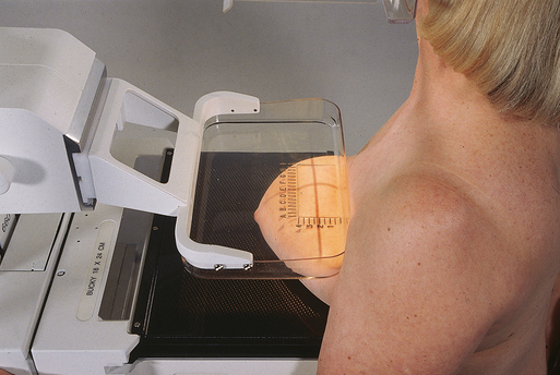
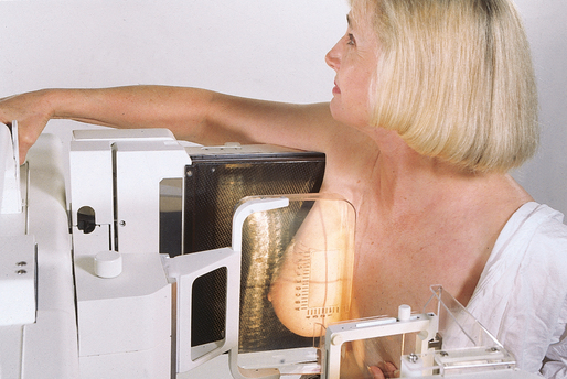
• Obtain an informed consent after discussing the following subjects with the patient:
1. Full explanation of the procedure
2. Full description of potential problems: vasovagal reaction, excessive bleeding, allergic reaction to lidocaine, and possible failure of the procedure (failure rate of 1% to 10%)
• Position the patient so that the compression plate is against the skin surface closest to the lesion as determined from the preliminary images.
• Tell the patient that compression will not be released until the needle has been successfully placed and that the patient is to hold as still as possible.
• Make a preliminary exposure using compression. Ink marks placed at the corners of the paddle window determine whether the patient moves during the procedure.
• Process the image without removing compression. The resultant image shows where the lesion lies in relation to the compression plate opening (Fig. 23-72).
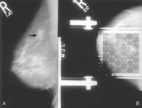
Fig. 23-72 Preliminary projections for breast localization procedure. A, Lateral projection is obtained to determine depth of lesion (arrow). B, Compression plate immobilizes breast for needle-wire insertion on CC projection. Alphanumeric grid shows that lesion is located nearest to E7 junction. Needle-wire is inserted through posterior aspect of hole E7.
• Clean the skin of the breast over the entry site with a topical antiseptic.
• Apply a topical anesthetic if necessary.
• Insert the localizing needle and guidewire into the breast perpendicular to the compression plate and parallel to the chest wall, moving the needle directly toward the underlying lesion. Advance the needle to the estimated depth of the lesion. Because the breast is compressed in the direction of the needle’s insertion, it is better to pass beyond the lesion than to be short of the lesion.
• With the needle in position, make an exposure (Fig. 23-73). Slowly release the compression plate, leaving the needle-wire system in place. Obtain an additional projection after the C-arm apparatus has been shifted 90 degrees (Fig. 23-74). These two orthogonal radiographs are used to determine the position of the end of the needle-wire relative to the lesion.
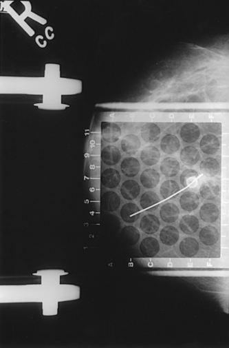
Fig. 23-73 Needle-wire localization device has been advanced through hole in compression plate to approximate location of lesion in CC projection.

Fig. 23-74 Second projection is obtained after x-ray tube is rotated 90 degrees. This projection allows depth of needle-wire localization system to be determined. Fenestrated compression plate is replaced with standard compression plate.
• Reposition the needle-wire, and repeat the exposures if necessary.
• When the needle is accurately placed within the lesion, withdraw the needle, but leave the hooked guidewire in place.
• Place a gauze bandage over the breast.
• Transport the patient to surgery along with the final localization images.
BREAST LESION LOCALIZATION WITHOUT A SPECIALIZED COMPRESSION PLATE
If a specialized fenestrated compression plate is not available or preferred, the procedure is as follows:
• Obtain preliminary routine full-breast projections to confirm the existence of the lesion. The MLO projection may be replaced by a 90-degree lateral projection.
• Obtain an informed consent after discussing the following subjects with the patient:
1. Full explanation of the procedure
2. Full description of potential problems, including vasovagal reaction, excessive bleeding, allergic reaction to lidocaine, and possible failure of the procedure (failure rate of 1% to 10%)
• Using the preliminary images, place an ink mark on the breast surface indicating the position of the lesion on each image. Taping alphanumeric radiopaque markers to the breast for the preliminary images can help define the position of the lesion relative to the breast surface in each projection. Because the breast is compressed for the exposures, it must resemble the compressed position to place the markers accurately. Using the hands, the mammographer reproduces this compression while the physician marks the surface of the breast at the appropriate sites (Figs. 23-75 and 23-76). Triangulation of the two surface marks fixes the three-dimensional location of the lesion.
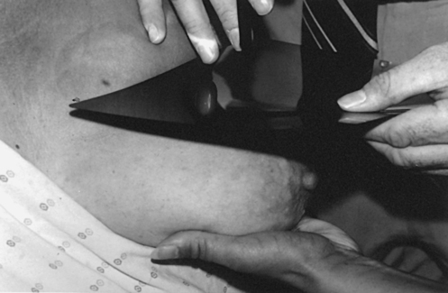
Fig. 23-75 Mammographer supports breast while physician superimposes CC projection mammogram over breast. This technique is used to locate a breast lesion in reference to skin surface.
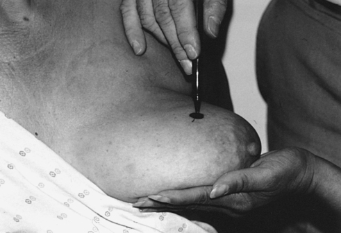
Fig. 23-76 Ink mark is placed on breast surface directly over breast lesion, locating lesion in CC projection. This technique is also used to place a mark over the lesion to locate lesion in ML projection.
• Clean the skin of the breast over the entry site with a topical antiseptic.
• Apply a topical anesthetic if necessary.
• Insert the needle, preferably parallel to the chest wall, toward the lesion for the predetermined distance (Fig. 23-77).
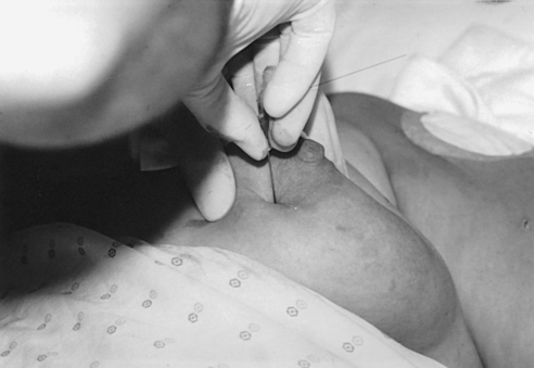
Fig. 23-77 Frank biopsy needle and guidewire are inserted into breast perpendicular to chest wall at site directly anterior to lesion. Site and depth of insertion are selected by triangulation using external skin marks.
• Image the breast in the CC and 90degree lateral projections with the needle-wire in place so that the exact location of the wire relative to the lesion can be determined.
• Reposition the needle-wire, and repeat the exposures if necessary.
• When the needle is accurately placed within the lesion, withdraw the needle and leave the hooked guidewire in place (Figs. 23-78 and 23-79).
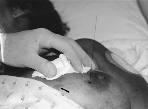
Fig. 23-78 After inserting needle and guidewire to depth of lesion, needle is removed, leaving guidewire in place. Lateral skin mark used for selecting needle insertion site is seen (arrow).
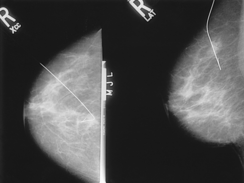
Fig. 23-79 CC and true lateral right-angle projections show relationship of wire to lesion. Needle has been removed.
• Place a gauze bandage over the breast.
• Transport the patient to surgery along with the final localization images.
STEREOTACTIC PROCEDURES
Approximately 80% of nonpalpable lesions identified by mammography are not malignant. Nonetheless, a breast lesion cannot be definitely judged benign until it has been microscopically evaluated. Stereotactic intervention, or stereotaxis, is a minor surgical procedure used to determine the benign or malignant nature of suspicious breast lesions. Stereotaxis guided by mammographic or ultrasound imaging is the preferred method for obtaining biopsy specimens of nonpalpable or equivocally symptomatic breast lesions. Most women with a mammographic or clinical breast abnormality are candidates for stereotactic core needle biopsy. The only exceptions are patients who cannot cooperate for the procedure, patients who have mammographic findings at the limits of perception, and patients with lesions of potentially ambiguous histology.
Stereotaxis is used to differentiate between benign and malignant breast lesions. The benefits of stereotaxis over conventional surgical biopsy are less pain, less scarring, shorter recovery time, less patient anxiety, and lower cost.
Because stereotaxis can expedite pathology results, potential surgical decisions such as regarding lumpectomy or mastectomy can be made with minimal delay. When operating on the basis of a core biopsy diagnosis of cancer, surgeons are more likely to obtain clean (negative) lumpectomy margins with the first excision. Axillary lymph nodes, which are evaluated to ascertain metastases, are also sampled at the time of the initial surgery. A woman with a known diagnosis of breast cancer may avoid a second operation.
Stereotactic breast biopsy requires a team approach involving a radiologist, a mammographer, a pathologist, and a specially trained nurse or technologist. Stereotactic prone biopsy tables and upright add-on devices used for biopsy intervention are commercially available. The disadvantages of the upright add-on system include a limited working space, an increased potential for patient motion, and a greater potential for vasovagal reactions (Fig. 23-80). The dedicated prone system is more expensive than the add-on system. It also requires a larger space and should not be used for conventional mammography (Figs. 23-81 and 23-82). The success or failure of core needle breast biopsy depends more on the experience and interest of the diagnostic team than on the particulars of the system that is used.
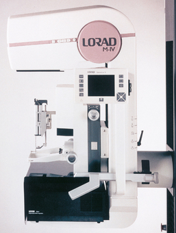
Fig. 23-80 Upright stereotactic system attached to dedicated mammography unit. (Courtesy Trex Medical Corp., LORAD Division, Danbury, CT.)
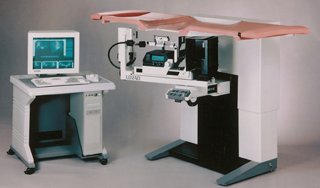
Fig. 23-81 Prone stereotactic biopsy system with digital imaging. (Courtesy Delta Medical Systems, Inc., Milwaukee, WI.)
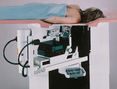
Fig. 23-82 Open aperture in table for prone biopsy system allows breast to be positioned beneath table. (Courtesy Trex Medical Corp., LORAD Division, Danbury, CT.)
In stereotactic breast biopsy, threedimensional triangulation is used to identify the exact location of a breast lesion. A digitizer calculates X, Y, and Z coordinates (Figs. 23-83 and 23-84). The X coordinate identifies transverse location (right to left), the Y coordinate designates depth (front to back), and the Z coordinate identifies the height of the lesion (top to bottom). Different stereotactic systems have different methods for calculating a Z value, depending on the center of rotation of the localization device. The operator should be familiar with the system in use so that accurate adjustments of the localization device can be made. Two exposures of a single position are taken at a difference of 30 degrees—one exposure at +15 degrees and the other at −15 degrees from the perpendicular. Precision of these angles is important. Also, with certain systems, the sequence of these images is significant in providing a correct value of lesion depth.
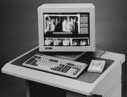
Fig. 23-83 Digitizer calculates and transmits X, Y, and Z coordinates to stage, or “brain,” of biopsy system, where biopsy gun is attached. This information is used to determine placement of biopsy needle. (Courtesy Trex Medical Corp., LORAD Division, Danbury, CT.)
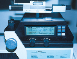
Fig. 23-84 Stage of biopsy system supports biopsy gun. X, Y, and Z coordinates are displayed. (Courtesy Delta Medical Systems, Inc., Milwaukee, WI.)
The resultant image localizes the lesion in three dimensions. The resultant images are referred to as the stereo image (Fig. 23-85). The physician can use the stereo image to determine the appropriate approach for reaching the breast lesion. Imaging with stereotactic units is available as either conventional screen-film or small-field (2 × 2 inch [5 × 5 cm]) digital imaging. Although conventional screen-film systems are considerably less expensive, digital imaging is preferred because of its shorter acquisition time.
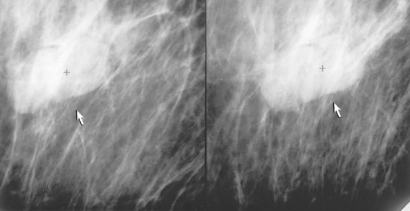
Fig. 23-85 Stereo images showing three-dimensional visualization of breast lesion before intervention (arrows).
Before beginning the procedure, the physician reviews the initial mammographic images to determine the shortest distance from the surface of the skin to the breast lesion. If the exact lesion location is identified, the biopsy needle can be inserted through the least amount of breast with only minimal trauma to the breast. A lesion located in the lateral aspect of the UOQ is approached from the lateral aspect, whereas a lesion located in the medial and superior portion of the breast is approached from above. After the best approach to the lesion has been determined, the affected breast is positioned and compressed for a scout image to localize the breast lesion. After the breast lesion has been localized, stereo images are taken to triangulate the lesion so that proper coordinates can be calculated and dialed into the biopsy table stage. The breast is aseptically cleansed to minimize infection. Pain associated with the procedure can be effectively managed using a local anesthetic to numb the skin at the area where the biopsy needle enters.
Three general methods can be used to localize a breast lesion. The physician’s preference generally determines the procedure that is performed. With needle-wire localization, the surgeon uses the hooked guidewire to find the biopsy site. In FNAB, cells are extracted from a suspicious lesion with a thin needle. LCNB obtains core samples of tissue by means of a larger needle with a trough adjacent to its tip. All three procedures can be performed using prone or upright stereotactic breast biopsy systems. Because LCNB with stereotactic guidance is becoming the preferred localization method, it is discussed in depth in this chapter.
The physician decides where the first and subsequent passes (biopsy needle travels through the breast tissue to reach the breast lesion) are to be made. After the skin is anesthetized, a small incision is made with a scalpel to facilitate entry of the needle into the breast. A spring-loaded biopsy device is used to power the needle back and forth through the target. A set of stereo images is obtained to confirm correct position of the needle (Fig. 23-86). The first pass is made by placing the biopsy needle within the lesion and obtaining a “postfire” image to confirm the correct needle placement. This image determines the course of subsequent passes. Redigitization (use of a digitizer to repeat the steps needed to calculate the new triangulation coordinates) can be performed to obtain additional samples. Alternatively, the physician can estimate where to move the biopsy needle based on the initial needle location within the breast. LCNB tissue samples are obtained using a needle with a trough adjacent to the needle tip. With the needle located inside the lesion, a sheath or needle cover slides over the trough of the needle. The sheath cuts the tissue sample within the trough and holds the sample in place while the needle is withdrawn. When the needle is outside the breast, the sheath is pulled back, exposing the tissue sample. The sample is transferred to a specimen container for transportation to the laboratory. A minimum of 5 to a maximum 20 tissue samples are obtained to ensure accurate sampling of the abnormality. The time required to perform a stereotactic procedure is approximately 40 to 50 minutes.
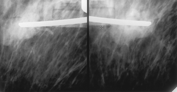
An alternative technique known as vacuum-assisted core biopsy uses a 14-gauge, 11-gauge, or 9-gauge probe that is inserted under stereotactic or ultrasound guidance to align the probe’s aperture within the lesion. Tissue is gently vacuum aspirated into the probe’s aperture. A rotating cutter is advanced to cut and capture the tissue sample. The cutter is withdrawn without removing the probe from the lesion, and the specimen is transported in the cutter to a tissue collection chamber. Multiple samples may be obtained by rotating the probe in vivo without multiple insertions. When the biopsy is complete, a radiopaque clip can be deployed through the probe and into the biopsy site to mark the area for future reference. The larger amount of tissue sampled with this technique is reported to improve accuracy in diagnosing atypical ductal hyperplasia and ductal carcinoma in situ lesions.1
After the LCNB procedure is completed, the breast is cleaned and bandaged using sterile technique. Compression to the biopsy site is necessary to prevent excessive bleeding, and a cold compress is applied to minimize discomfort and swelling of the related tissues.
The patient may be asked to return within 24 to 48 hours so that the breast can be examined to ensure that no bleeding or infection has occurred. The physician who performed the biopsy discusses the biopsy results and subsequent treatment options, if applicable, with the patient.
Breast Specimen Radiography
When open surgical biopsy is performed, the suspected lesion must be contained in its entirety in the tissue removed during the biopsy. Very small lesions that are characterized by tissue irregularity or microcalcifications on a mammographic image and that are nonpalpable in the excised specimen may be undetectable on visual inspection; a radiographic image of the biopsied tissue may be necessary to determine that the entire lesion has been removed. Compression of the specimen is necessary to identify lesions, especially lesions that do not contain calcifications. Magnification imaging is used to help visualize microcalcifications better. Specimen radiography is often performed in an immediate postexcision procedure while the patient is still under anesthesia. Speed is imperative.
The procedure for handling the specimen must be established before the procedure is started. Cooperation among the radiologist, mammographer, surgeon, and pathologist is imperative. Together, a system of identifying the orientation of the tissue sample to the patient’s breast (anterior, posterior, medial, or lateral aspect of the sample) can be applied to aid in determining that the lesion has been completely removed. Extremely fine-grain, nonscreen film may be used because patient exposure is no longer a factor. The exposure factors depend on the thickness of the specimen and the film that is used (Fig. 23-87). Alternatively, radiographic equipment is manufactured specifically for imaging tissue specimens. These units are self-contained, often portable, and allow specimens to be imaged directly in the operating suite. Digital technology allows the image to be seen by the surgeon and the radiologist and the pathologist in remote locations, almost immediately and simultaneously.
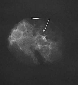
If using film-screen technology, it may be helpful to obtain one image of the breast specimen for the radiologist and another for the pathologist. The pathologist often uses the specimen radiograph to locate the area of concern precisely. The next step is to match the actual specimen to the specimen radiograph before the specimen is dissected. Marking the area of concern by placing a radiopaque object, such as a 1- or 2-inch (2.5- or 5-cm) needle, directly at the area of concern helps the pathologist locate the abnormality more accurately.
Specimens of tissue from LCNB are also frequently radiographed, particularly when the biopsy is performed for calcifications. Radiographing the tissue specimens can confirm that the area of interest has been sampled and is included within the sample.
Ductography (Examination of Milk Ducts)
When a nipple discharge is localized in one of the multiple duct openings on the nipple, the milk duct can be studied using an opaque contrast medium. The purpose of the examination is to rule out an intraductal cancer or to determine whether a benign mass such as a papilloma is the cause of the discharge. The equipment and supplies for the examination include a sterile hypodermic syringe (usually 1 to 3 mL); a 30-gauge ductography cannula with a smooth, round tip; a skin cleansing agent; sterile gauze sponges or cotton balls; paper tape; a waste basin; and an organic, water-soluble, iodinated contrast medium.
After the nipple is cleaned, a small amount of discharge is expressed to identify the correct ductal opening. The cannula is inserted into the orifice of the duct, and undiluted iothalamate meglumine or iopamidol is gently injected. So that the patient does not experience unnecessary discomfort and extravasation does not occur, the injection is terminated as soon as the patient experiences a sense of fullness, pressure, or pain. The cannula is taped in place before positioning the patient for the radiographs. If cannulation is unsuccessful, a sterile local anesthetic gel or warm compress may be applied to the nipple and areola, and the procedure is reattempted. If ductography is unsuccessful after several attempts, the procedure may be rescheduled in 7 to 14 days. On successful injection, the following guidelines are observed:
• Immediately obtain radiographs with the patient positioned for the CC and lateral projections of the subareolar region using magnification technique (Fig. 23-88). If needed, MLO or rolled CC and rolled MLO magnification projections may be obtained to resolve superimposed ducts.
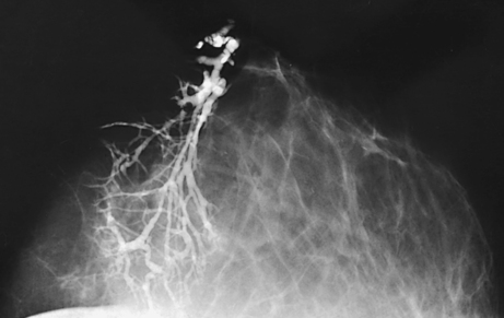
• Employ the exposure techniques used in general mammography.
• Leave the cannula in the duct to minimize leakage of contrast material during compression and to facilitate reinjection of the contrast medium without the need for recannulation.
• If the cannula is removed for the images, do not apply vigorous compression because it would cause the contrast medium to be expelled.
Computer-Aided Detection
When performing mammographic interpretation, the radiologist must locate any suspicious lesions (sensitivity) and then determine the probability that the lesion is malignant or benign (specificity). Even with high-quality mammography, some breast cancers are missed on initial interpretation. Double-reading of screening mammograms by a second radiologist can improve detection rates by approximately 10%.1 Efforts have been made to develop and apply a computer-aided detection (CAD) system to achieve the same result as double-reading. It has also been found that double-reading plus the use of CAD can increase detection rates by an additional 8%.2
CAD is a method by which a radiologist can use computer analysis of digitally acquired images as a “second opinion” before making a final interpretation. CAD works similar to a spell-check on a computer; an area is pointed out for the radiologist to check, but it is up to the radiologist to decide whether the area is suspicious enough to warrant any additional procedures. CAD requires that the mammographic image exist in a digital format to facilitate computer input. The use of images directly acquired with full-field digital technology is preferred; however, CAD can also be accomplished on film images with the use of an optical scanner. The computer may detect lesions that are missed by the radiologist, minimizing the possibility of false-negative readings (Fig. 23-89). When a lesion is detected, the computer can be programmed with basic algorithms to estimate the likelihood of malignancy, increasing true-positive rates. Ultimately, the objective of this technology is to improve early detection rates and minimize the number of unnecessary breast biopsies. Another advantage of CAD is that computers are not subject to the bias, fatigue, or distractions to which a radiologist may be subject. Because of the high rate of sensitivity and specificity shown by CAD, it has become a standard of care for many mammography practices.
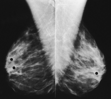
Full-Field Digital Mammography
Mammography has been the last area in the field of radiography to take advantage of digital technology. In addition to the many technical issues with FFDM, the prohibitive cost of the equipment and its maintenance do not make digital mammography practical for all facilities. Its many advantages in imaging dense breast tissue have been the motive, however, for more than 50% of mammography facilities in the United States to transition to this technology.
FFDM units allow radiologists to manipulate the digital images electronically, potentially saving patients from undergoing additional projections and additional radiation. The ability to manipulate the digital images improves the sensitivity of mammography, especially in women with dense breast tissue. The results of the ACRIN DMIST study, a multifacility, multiunit study comparing film-screen mammography with digital mammography, was published in September 2005.1 The authors of this study concluded that FFDM would benefit some patients, specifically women younger than age 50, premenopausal and perimenopausal women, and women of any age with dense breast tissue. Because there are patients who would benefit from digital mammography, it is destined to become even more dominant in the future. In the meantime, if FFDM is unavailable to women who fall within these benefit guidelines, they should continue having film-screen mammography studies because it has successfully been used as a screening tool for breast cancer for more than 35 years.
Digital breast imaging requires a much finer resolution than other body imaging. FFDM images are extremely large files that require a great deal of archival space in PACS. Because of regulations safeguarding the image quality of mammography, the images cannot be interpreted on a traditional PACS workstation; they can be interpreted only on special 5-megapixel monitors.
Innovative solutions and approaches to FFDM continue to be developed. A promising offshoot of FFDM is breast tomosynthesis, a three-dimensional imaging technology that involves acquiring images of a stationary, compressed breast at multiple angles during a short scan. These images are econstructed into thin, high-resolution slices that can be displayed individually or in a dynamic cine mode. These units can simultaneously acquire the traditional two-dimensional mammogram and the additional exposures necessary to reconstruct a three-dimensional image. At the present time, the technology is very close to U.S. Food and Drug Administration (FDA) approval and is in position to be the next major technical advancement in breast imaging.
Breast Magnetic Resonance Imaging
Breast MRI has proven to be most useful in patients with proven breast cancer or at high risk to assess for multifocal or multicentric disease, chest wall involvement, chemotherapy response, or tumor recurrence or to identify the primary site in patients with occult breast disease.
INDICATIONS
Assessment of extent of disease and residual disease
MRI can be helpful for patients who have had a lumpectomy and have positive margins and no evidence of residual disease on conventional imaging (mammography, ultrasound). Postoperative mammography can help detect residual calcifications but is limited for residual mass. MRI is very sensitive for detection of residual mass and identifies other potential suspicious sites seen on MRI only.
Assessment of tumor recurrence
Assessment of tumor recurrence can be very complicated on MRI because scars can enhance for 1 to 2 years after surgery. Suggestion of recurrence can be made by MRI, yet the cost of the procedure should be weighed against a less expensive needle biopsy of the area.
Occult primary breast cancer
Patients with axillary metastases suspicious for primary breast cancer with a negative physical examination, mammogram, and ultrasound are good candidates for MRI because of its high sensitivity for invasive cancers. MRI has been shown to detect 90% to 100% of cancers if tumor is present in the breast. If the primary site is detected, the patient may be spared a mastectomy, and MRI can influence patient surgical management.
Neoadjuvant chemotherapy response
In patients with advanced breast cancer, MRI may be able to predict earlier which patients are responding to chemotherapy. Mammography and physical examination can sometimes be limited by fibrosis. Studies suggest that MRI may be better at assessing patients’ response to treatment.1
High-risk screening
Breast MRI is recommended as an annual screening examination for patients at high risk for developing breast cancer.1 These include women
1. Who have a first-degree relative (parent, sibling, child) with a BRCA1 or BRCA2 mutation, even if they have yet to be tested themselves.
2. Whose lifetime risk of breast cancer has been scored at 20% to 25% or greater, based on one of several accepted risk assessment tools that look at family history and other factors.
3. Who have had radiation to the chest between the ages of 10 and 30.
4. Who have Li-Fraumeni syndrome, Cowden syndrome, or Bannayan-RileyRuvalcaba syndrome or may have one of these syndromes based on a history in a first-degree relative.
A study published in the New England Journal of Medicine concluded that MRI is “more sensitive than mammography in detecting tumors in women with an inherited susceptibility of breast cancer.”2 At the present time, not all insurance companies cover breast MRI in these high-risk women.
Breast MRI is recommended for women at high risk to be used as an adjunct to mammography. The most beneficial method for screening is to schedule 6-month intervals alternating MRI with mammography. Women who are found to have MRI-detected foci suspicious of cancer need to have these verified by biopsy. Often these areas are reexamined with mammography and directed ultrasound for potential biopsy. If these lesions are not found by conventional imaging, confirmation with MRI-guided biopsy would be necessary before committing the patient to potential lumpectomy or mastectomy or both.
Thermography and Diaphanography
Beginning in the 1950s, thermography and diaphanography were actively investigated in the hope that breast cancer and other abnormalities could be diagnosed using nonionizing forms of radiation. These two diagnostic tools are seldom used today.
Thermography is the photographic recording of the infrared radiation emanating from a patient’s body surface. The resulting thermogram shows areas of increased temperature, with a temperature increase often suggesting increased metabolism. (More complete information on this technique is provided in the fourth through eighth editions of this atlas.)
Diaphanography is an examination in which a body part is transilluminated using selected light wavelengths and special imaging equipment. With this technique, the interior of the breast is inspected using light directed through its exterior wall. The light exiting the patient’s body is recorded and interpreted. The rapid advances in mammography have essentially eliminated the use of this technique for evaluating breast disease. (More complete information on diaphanography is given in this chapter in the fourth through eighth editions of this atlas.)
Conclusion
Radiographic examination of the breast is a technically demanding procedure. Success depends in large part on the skills of the mammographer—more so than in most other areas of radiology. In addition to skill, the mammographer must have a strong desire to perform high-quality mammography and must be willing to work with the patient to allay qualms and to obtain cooperation. In the course of taking the patient’s history and physically assessing and radiographing the breasts, the mammographer may be asked questions about breast disease, BSE, screening guidelines, and breast radiography that the patient has been reluctant to ask other health care professionals. The knowledge, skill, and attitude of the mammographer may be lifesaving for the patient. Although most patients do not have significant breast disease when first examined, statistics show that approximately 12% of patients develop breast cancer at some time during their lifetime. An early positive mammography encounter may make the patient more willing to undergo mammography in the future. When properly performed, breast radiography is safe, and it presently is the best hope for significantly reducing the mortality of breast cancer.
Adler, D, Wahl, R. New methods for imaging the breast: techniques, findings and potential. AJR Am J Roentgenol. 1995;164:19.
American Cancer Society. Breast cancer facts and figures 1999/2000. Available at: www.cancer.org. Accessed April 2001.
Appelbaum, A, et al. Mammographic appearance of male breast disease. RadioGraphics. 2001;19:559.
Bassett, L. Imaging of breast masses. Radiol Clin North Am. 2000;38:669.
Bassett L, et al, eds. Quality determinants of mammography, AHCPR Pub No 95-0632. Rockville, MD: U.S. Department of Health and Human Services, 1994.
Burbank, F. Stereotactic breast biopsy of atypical hyperplasia and ductal carcinoma in situ lesions: improved accuracy with directional, vacuum-assisted biopsy. Radiology. 1997;202:843.
Carr, J, et al. Stereotactic localization of breast lesions: how it works and methods to improve accuracy. RadioGraphics. 2001;21:463.
Dershaw, DD. Equipment, technique, quality assurance, and accreditation for image-guided breast biopsy procedures. Radiol Clin North Am. 2000;38:773.
Dershaw, DD, et al. Mammographic findings in men with breast cancer. AJR Am J Roentgenol. 1993;160:267.
Eklund, GW, Cardenosa, G. The art of mammographic positioning. Radiol Clin North Am. 1992;30:21.
Eklund, GW, et al. Improved imaging of the augmented breast. AJR Am J Roentgenol. 1988;151:469.
F-D-C Reports, Inc. ImageChecker unanimously endorsed by radiology panel. Medical devices, diagnostics, and instrumentation: “the gray sheet”. 1998;24:20.
Feig, S. Breast masses: mammographic and sonographic evaluation. Radiol Clin North Am. 1992;30:67.
Haus, A, Yaffe, M. Screen-film and digital mammography image quality and radiation dose considerations. Radiol Clin North Am. 2000;38:871.
Healy, B. BRCA genes: bookmarking, fortunetelling, and medical care. N Engl J Med. 1997;336:1448. (editorial).
Henderson, IC. Breast cancer. In: Murphy GP, Lawrence WL, Lenhard RE, eds. Clinical oncology. Atlanta: American Cancer Society, 1997.
Jackson, V. The status of mammographically guided fine needle aspiration biopsy of nonpalpable breast lesions. Radiol Clin North Am. 1992;30:155.
Kopans, DB. Double reading. Radiol Clin North Am. 2000;38:719.
Krainer, M, et al. Differential contributions of BRCA1 and BRCA2 to early-onset breast cancer. N Engl J Med. 1997;336:1416.
Liberman, L. Clinical management issues in percutaneous core breast biopsy. Radiol Clin North Am. 2000;38:791.
Logan-Young, W, et al. The cost effectiveness of fine-needle aspiration cytology and 14-gauge core needle biopsy compared with open surgical biopsy in the diagnosis of breast cancer. Cancer. 1998;82:1867.
Mammography quality control manual, rev. ed. Chicago: American College of Radiology, 1999.
National Cancer Institute CancerNet. Available at: www.cancernet.nci.nih.gov. Accessed April 2001.
Nishikawa, R, et al. Computerized detection of clustered microcalcifications: evaluation of performance on mammograms from multiple centers. RadioGraphics. 1995;15:443.
Orel, SG. MR imaging of the breast. Radiol Clin North Am. 2000;38:899.
Parker, SL, Burbank, F. A practical approach to minimally invasive breast biopsy. Radiology. 1996;200:11.
Parker, SL, et al. Percutaneous large-core breast biopsy: a multi-institutional study. Radiology. 1994;193:359.
Prechtel, K, Pretchel, V. Breast carcinoma in the man: current results from the viewpoint of clinic and pathology. Pathologe. 1997;18:45.
Rozenberg, S, et al. Principal cancers among women: breast, lung, and colorectal. Int J Fertil. 1996;41:166.
Schmidt, R, Wolverton, D, Vyborny, C. Computer-aided diagnosis in mammography. In RSNA categorical course in breast imaging [syllabus]. Oak Park, IL: RSNA; 1995.
Skolnick, AA. Ultrasound may help detect breast implant leaks. JAMA. 1992;267:786.
Slawson, SH, et al. Ductography: how to and what if? RadioGraphics. 2001;21:133.
Vyborny, CJ. Computer-aided detection and computer-aided diagnosis of breast cancer. Radiol Clin North Am. 2000;38:725.
1American Cancer Society: Cancer facts and figures 2004, Atlanta, 2004, American Cancer Society, p 9.
1Haus AG: Screen-film and digital mammography image quality and radiation dose considerations, Radiol Clin North Am 38:871, 2000.
22Spelic DC: FDA Updated trends in mammography dose and image quality—related article: dose and image quality in mammography: trends during the first decade of MQSA, Available at www.FDA.gov. Accessed August 18, 2009.
1National Cancer Institute, Available at: www.cancer.gov. Accessed August 16, 2006.
1Bassett L, Heinlein R: Good positioning key to imaging of breast, Diagn Imaging 9:69, 1993.
1Orel SG: MR imaging of the breast, Radiol Clin North Am 38:899, 2000.
1Appelbaum A et al: Mammographic appearance of male breast disease, RadioGraphics 19:559, 2001.
2National Cancer Institute Factsheet, Available at: www.cancer.gov. Accessed August 14, 2009.
1Eklund GW, Cardenosa G: The art of mammographic positioning, Radiol Clin North Am 30:21, 1992.
1Dershaw DD: Equipment, technique, quality assurance, and accreditation for image-guided breast biopsy procedures, Radiol Clin North Am 38:773, 2000.
1Kopans DB: Double-reading, Radiol Clin North Am 38:719, 2000.
22Destounis SV et al: Can computer-aided detection with double reading of screening mammograms help decrease the false-negative rate? Initial experience, Radiology 232:578, 2004.
11Pisano E et al: Diagnostic performance of digital versus film mammography for breast cancer screening, N Engl J Med 353:1773, 2005.
1Yeh E et al: Prospective comparison of mammography, sonography, and MRI in patients undergoing neoadjuvant chemotherapy for palpable breast cancer, AJR Am J Roentgenol 184:868, 2005.
11American Cancer Society, March 2007.
22Kriege M et al: Efficacy of MRI and mammography for breast cancer screening in women with a familial or genetic predisposition, N Engl J Med 351:427, 2004.