COMPENSATING FILTERS
Introduction
In most cases, radiography is accomplished using a single exposure technique for a given body structure. Some structures contain areas of significantly varied tissue thickness and density that must be shown on one image, however. These structures present special challenges in showing the anatomic structures with an acceptable range of densities. Often, two exposures must be made on these body structures, doubling the radiation exposure to the patient.
Typically, if one exposure is used, a technique is selected to penetrate adequately the densest area of anatomy. In this case, the radiologist highlights the dark anatomic area on the image with a “hot-light.” These images often have to be viewed by other physicians without having such a light available. With digital radiography systems, the image can be adjusted with the computer to lighten the dark area of anatomy; however, the large difference in transmitted x-rays often exceeds the dynamic range of the software. Images that appear low in contrast, contain high noise, or show processing artifacts can result. Clinical experience shows that compensating filters improve digital images.
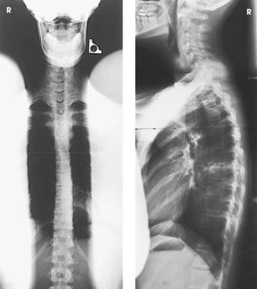
Examples of x-ray projections that have to show significantly varied tissue density include the anteroposterior (AP) projection of the thoracic spine, the axiolateral projection (Danelius-Miller method) of the hip, and the lateral cervicothoracic region (swimmer’s technique) (Fig. 2-1). Exposure of these structures with a uniformly intense x-ray beam results in the production of an image with areas of underexposed or overexposed anatomy. To compensate for these variations in tissue density, specially designed attenuating devices called compensating filters can be placed between the radiographic tube and the image receptor (IR). The resulting attenuated beam more appropriately exposes the various tissue densities of the anatomy and reveals more anatomic detail. Equally important, the filter reduces the entrance skin exposure and the dose to some of the organs in the body (Fig. 2-2).
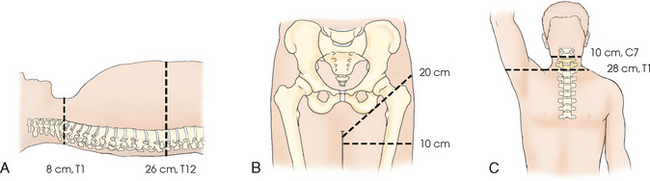
Fig. 2-1 A-C, Body structures with significantly varied tissue thickness and density include thoracic spine (AP) (A), hip (lateral) (B), and cervicothoracic region (lateral) (C). Note different thicknesses in these areas. Use of compensating filters allows these structures to be shown with one exposure.
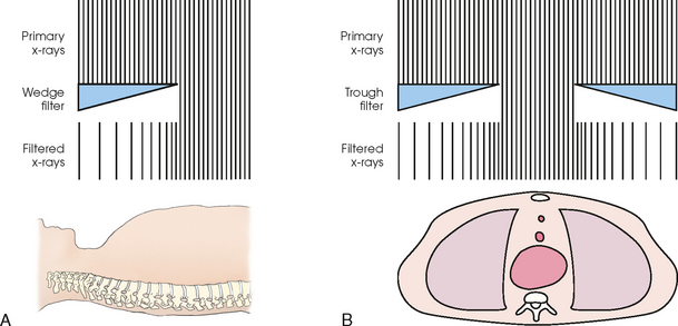
Fig. 2-2 A, Wedge filter in position for AP projection of thoracic spine. Note how thick portion of wedge partially attenuates x-ray beam over upper thoracic area while nonfilter area receives full exposure to penetrate thick portion of spine. An even image density results. B, Trough filter in position for AP projection of chest. Note how two side wedges partially attenuate x-ray beam over lung areas while mediastinum receives full exposure. A better-quality image of chest and mediastinal structures results.
The technique of compensatory filtration was first applied in 1905 by Pfahler, 1 not long after x-rays were first discovered. Pfahler used wet shoe leather as the filter by wrapping it around a patient’s arm. Compensating filters of one type or another have been in use since that time. Some of the most common filters in use today are shown in Fig. 2-3. These filters can be used with screen-film and digital imaging systems to improve the image quality of various anatomic areas. With most digital systems, filters are necessary to obtain a diagnostic image of a body part with extreme differences in density. In addition, radiation exposure to the patient is reduced through elimination of extra exposures needed to show all of the anatomy and through the beam-hardening effect of the attenuating filter. The increasing thickness of the filter over the thinner body part also acts to reduce exposure.
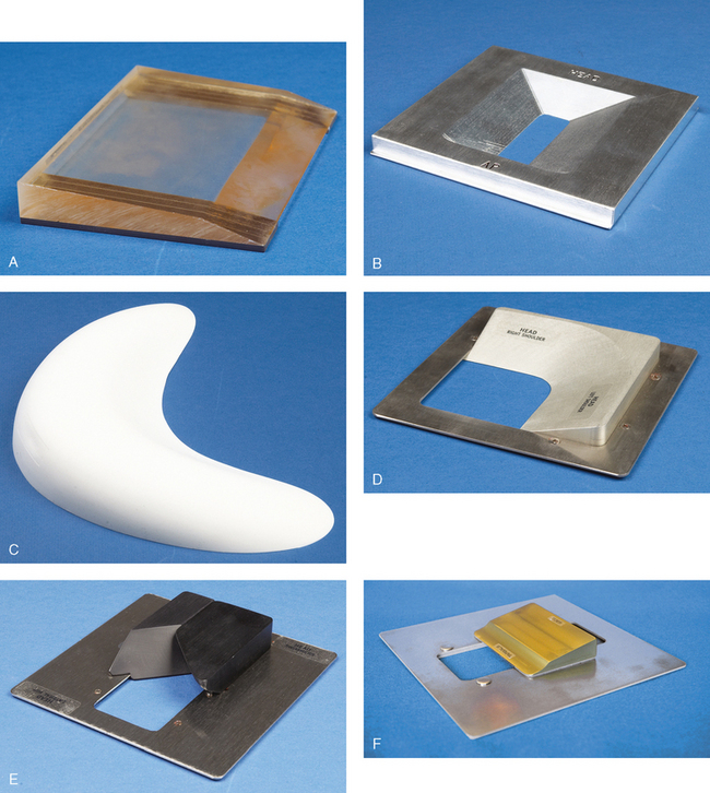
Fig. 2-3 Examples of compensating filters in use today. A, Supertech wedge, collimator-mounted Clear Pb filter used for AP projection of hips, knees, and ankles on long (51-inch) film. B, Trough, collimator-mounted aluminum filter with double wedge used for AP projections of thoracic spine. C, Boomerang contact filter used for AP projections of shoulder and facial bones. D, Ferlic collimator-mounted filter used for AP and PA oblique (scapular Y) projections of shoulder. E, Ferlic collimator-mounted filter used for lateral projections of cervicothoracic region (swimmer’s technique) and axiolateral projections (Danelius-Miller method) of hip. F, Ferlic collimator-mounted filter for AP axial projections of foot.
The appropriate use of radiographic compensating filters is an important addition to the radiographer’s skill set. The radiographer determines whether or not to use a filter based on an assessment of the patient and determines the type and exact position of the filter. This determination is made while positioning the patient. Radiographic projections of the lateral hip and the lateral C7-T1 cervicothoracic region in most instances require a filter to show all the anatomy on one image. Projections such as the AP shoulder and AP thoracic spine may not need a filter on hyposthenic patients; however, on hypersthenic patients and patients who are “barrel-chested” or obese, a filter is necessary. Pediatric patients seldom require a filter except when posteroanterior (PA) and lateral projections of the full spine are done in cases of spinal curvatures such as scoliosis. Compensating filters for full-spine radiography not only allow the entire spine to be imaged with one exposure, but they also significantly reduce the radiation exposure to the young patients who require these images.1–3
Physical Principles
Compensating filters are manufactured in various shapes and are composed of several materials. The shape or material chosen is based on the particular body part to be imaged. The exact placement of the filter also varies, with most being placed between the x-ray tube and the skin surface, although some are placed under the patient. Filters placed under the patient often produce distinct outlines of the filter, which can be objectionable to the radiologist.
SHAPE
The wedge is the simplest and most common of the compensating filter shapes. It is used to improve the image quality of a wide variety of body parts. Various filters with more complex shapes have been developed for technically challenging anatomic areas, including the trough, scoliosis, Ferlic,1 and Boomerang.2
Some filters have multiple uses. A filter that is shaped for one area of the body can also be adapted for other body structures. Filters such as the Ferlic cervicothoracic lateral projection (swimmer’s technique) filter can be adapted for the axiolateral projection (Danelius-Miller technique) of the hip with excellent results.
COMPOSITION
Compensating filters are composed of a substance of sufficiently high atomic number to attenuate the x-ray beam. The most common filter materials are aluminum and high-density plastics. These are manufactured with different thickness of the material and generally distributed in a smoothly graduated way that corresponds with the distribution of the different tissue densities of the anatomy (see Fig. 2-2). Aluminum is an efficient attenuator and a common filter material.
Some manufacturers offer compensating filters made from clear leaded plastic, known as Clear Pb,1 which allows the field light to shine through to the patient but still attenuates the x-ray beam (Fig. 2-3, A). This leaded plastic is inappropriate for all filter uses, however, such as in the extremely dense area of the shoulder during lateral spine radiography because the thickness required to attenuate the beam sufficiently would result in a prohibitively heavy device. In these cases, aluminum is generally used. The Boomerang (see Fig. 2-3, C) filter is composed of an attenuating silicon rubber compound, and some models of this filter have an embedded metal bead chain to mark the filter edge.
PLACEMENT
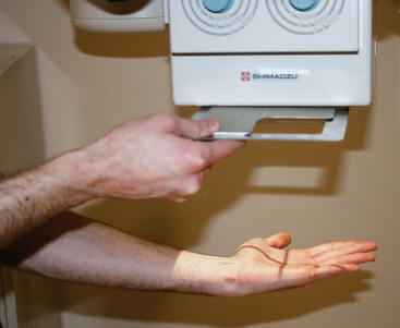
Compensating filters are most often placed in the x-ray beam between the x-ray tube and patient. Broadly, filters fall into two categories based on their location during use: collimator-mounted filters and contact filters. Collimator-mounted filters are mounted on the collimator, using either rails installed on both sides of the window on the collimator housing (Fig. 2-4, A) or magnets. Contact compensating filters are placed either directly on the patient or between the anatomy and the IR (Fig. 2-4, B).
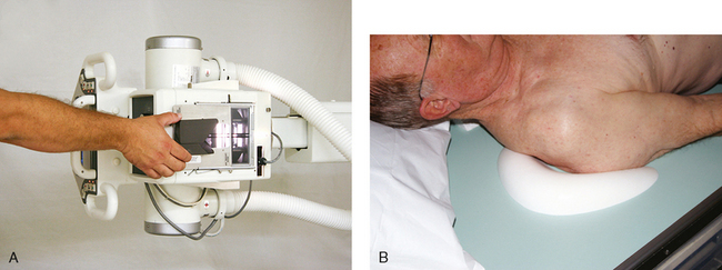
Fig. 2-4 A, Ferlic collimator-mounted filter positioned on collimator for AP projection of shoulder. B, Boomerang contact filter in position for AP projection of shoulder. (A, Courtesy Scott Slinkard, College of Nursing and Health Sciences, Cape Girardeau, MO.)
Collimator mounted filters made of aluminum block the field light, which makes positioning of the patient and the central ray more challenging. Many aluminum filters have a 100% x-ray transmission zone (see Fig. 2-3, B, D, E, and F), and positioning is made slightly easier. Radiographers who use aluminum filters must complete the positioning of the patient and alignment of the central ray first before mounting the filter to the collimator (Fig. 2-5).
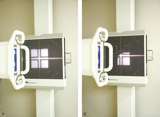
Fig. 2-5 A, Collimator light adjusted for AP projection of right shoulder. B, Ferlic shoulder filter in place showing 100% transmission area (light) and remaining area blocked by aluminum of filter. (Courtesy Scott Slinkard, College of Nursing and Health Sciences, Cape Girardeau, MO.)
Generally, filters placed between the primary beam and the body have the added benefit of a reduction in radiation exposure to the patient because of the beam-hardening effect of the filter, whereas filters placed between anatomy and the IR have no effect on patient exposure. Measurements provided with Ferlic filters show radiation exposure reductions of 50% to 80%, depending on the kilovoltage peak (kVp), in the anatomic area covered by the filter. Measurements by Frank et al.1 show exposure reductions of 20% to 69% to the thyroid, sternum, and breasts. Both types have the same effect on the finished image, which is a more uniform radiographic density even though the tissue density varied greatly. Filters can be improvised as well, with radiographers creating their own version of attenuation control devices, such as filled bags of saline solution. Bags of solution increase scattered radiation, however. Use of improvised filters is not recommended because there is potential for creating unknown artifacts in the image.
Specific Applications
The choice of compensating filter to be used depends on the distribution of tissue densities of the anatomy to be radiographed. As illustrated in Table 2-1, most of these imaging challenges can be solved with only a few filter shapes. The following are examples of the most common compensating filter applications.
TABLE 2-1
Common x-ray projections for which filters improve image quality*

*This table is not all-inclusive. Other body structures can be imaged, and other filters are available on the market.
†Ferlic; Ferlic Filter Company, LLC, White Bear Lake, MN.
‡Boomerang; Octostop, Inc., Laval, Canada.
§Supertech, Elkhart, IN.
• The wedge filter is used for areas of the body where tissue density varies gradually from one end to the other along the long axis of the body. The wedge filter can be used to improve image quality of AP projections of the thoracic spine (Fig. 2-6).
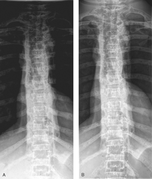
Fig. 2-6 A, AP projection of thoracic spine without compensating filter. B, Same projection with Ferlic wedge filter. Note more even density of spine, and all vertebrae are shown.
• The trough filter is best used for areas of the body where the subject density in the center is much greater than at the edges. This filter has been successfully applied to improving PA projections of the chest (Fig. 2-7).
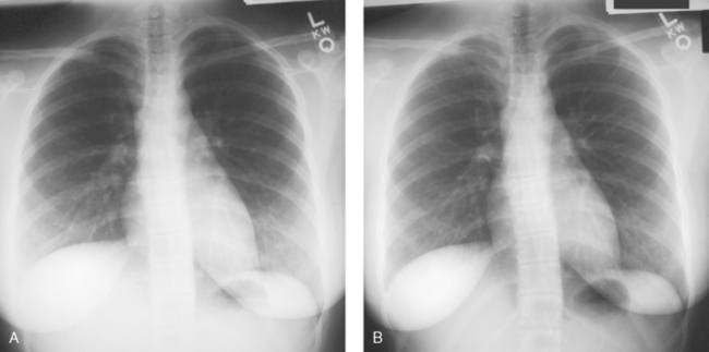
Fig. 2-7 A, AP projection of chest without compensating filter. B, Same projection with Supertech trough filter. Lower lung fields and mediastinum are better shown.
• The Ferlic swimmer’s filter is a collimator-mounted filter created to improve imaging of the lateral projection of the cervicothoracic region (swimmer’s technique) (Fig. 2-8), but it is also used for the axiolateral projection of the hip (Danelius-Miller method) (Fig. 2-9). The Ferlic shoulder filter, also a collimator-mounted filter, is designed specifically to image the shoulder in both the supine and upright positions.
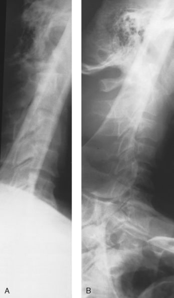
Fig. 2-8 A, Lateral projection of cervicothoracic region (swimmer’s technique) without compensating filter. B, Same projection with Ferlic swimmer’s filter. Note how C7-T1 area is penetrated and shown.
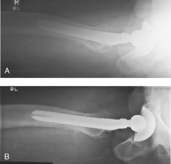
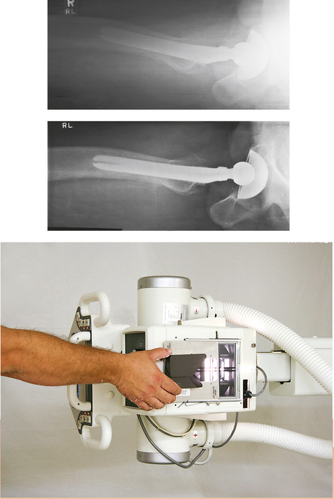
Fig. 2-9 A, Axiolateral projection of hip (Danelius-Miller method) without compensating filter. B, Same projection with Ferlic swimmer’s filter. Note how acetabulum and end of metal shaft are seen on one image.
• Specialized wedge filters are designed for specific uses. Fig. 2-10 shows the results of using the Ferlic foot filter to provide a significantly improved image of the foot with one exposure.
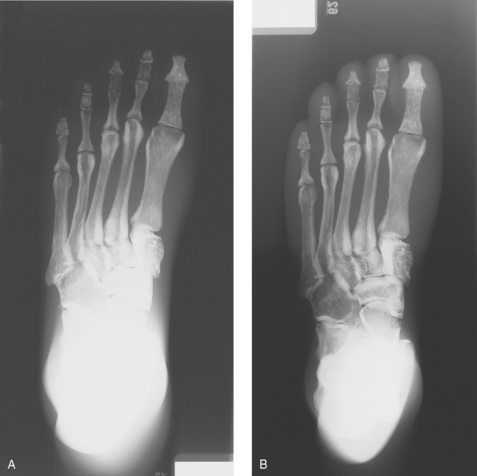
Fig. 2-10 A, AP axial projection of foot. Note dark toe area and light tarsal area without filter. B, Same projection with use of Ferlic AP foot filter showing improved visualization of toes and tarsals.
• The Boomerang filter was designed to conform to the shape of the shoulder and create images of more uniform radiographic density at the superior margins (Fig. 2-11). This is a contact filter placed between the anatomy and the IR (see Fig. 2-4, B). It can also be used effectively for lateral facial bone images. Although effective in compensating for differences in anatomic density, this filter does not reduce radiation exposure because it is located behind the patient. The Ferlic shoulder filter is a collimator-mounted filter also designed specifically to image the shoulder (Fig. 2-12). Because this filter is placed in the primary x-ray beam, it also acts to reduce radiation exposure to the patient.
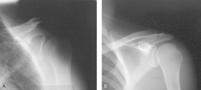
Fig. 2-11 A, AP projection of shoulder without compensating filter. B, Same projection using Boomerang contact filter.
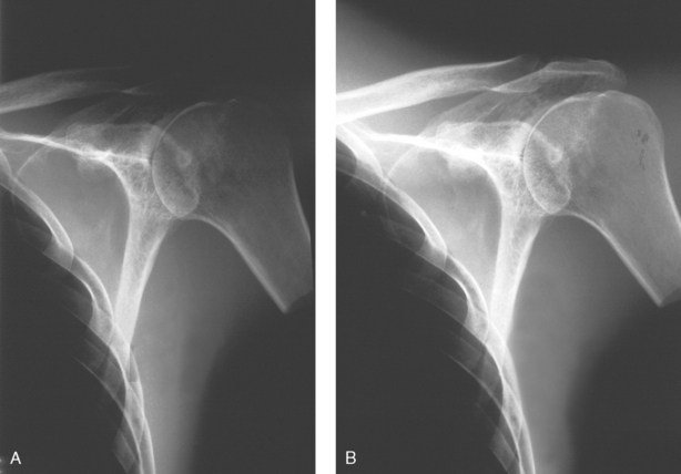
Fig. 2-12 A, AP projection of shoulder without compensating filter. B, Same projection using Ferlic shoulder collimator mounted filter. Note greater visualization of acromion, acromioclavicular joint, and humeral head.
• The scoliosis filters are used with two of the most challenging projections to obtain: the PA (Frank et al. method) and lateral full-spine projections for evaluation of spinal curvatures. These projections are challenging because the cervical, thoracic, and lumbosacral spines have to be shown on one image. One exposure technique has to be set for what normally would be three separate exposures. With the use of compensating filters, the PA projection can be made with a wedge filter positioned over the cervical and thoracic spines (Fig. 2-13, A). For the lateral projection, two double-wedge filters are positioned over the mid-thoracic area and the cervical spine (Fig. 2-13, B). The exposure technique for the PA and lateral projections is set to penetrate the most dense area—the lumbar spine. The filters attenuate enough of the exposure over the cervical and thoracic areas to show the thoracic and cervical spines adequately.
Highly specialized compensating filters are also used in other areas of the radiology department. During digital fluoroscopy, convex and concave conical-shaped filters are used to compensate for the round image intensifier. In computed tomography (CT), “bow-tie”–shaped filters are used to compensate for the rounded shape of the head.
Radiographers must use caution when mounting and removing compensating filters on the collimator while the x-ray tube is over the patient. There have been instances when filters did not attach properly, did not get positioned into the filter track, or were forgotten and fell onto the patient when the tube was moved. All compensating filters, especially aluminum ones, are moderately heavy with sharp edges; they can cause injury to the patient if dropped. When positioning the filter to the underside of the collimator and when removing it, two hands must be used (Fig. 2-14). One hand should attach the filter while the other is positioned to catch the filter if it does not attach properly.
Compensating Filters in This Atlas
Body structures whose radiographic images can be improved through the use of compensating filters are identified throughout the atlas directly on the projection page. The special icon  identifies the use of a filter.
1Pfahler GE: A roentgen filter and a universal diaphragm and protecting screen, Transcripts of the American Roentgen Ray Society 217, 1906.
1Gray JE, Stears JG, Frank ED: Shaped, lead-loaded acrylic filters for patient exposure reduction and image quality improvement, Radiology 146:825, 1983.
2Frank ED et al: Use of the posterior-anterior projection as a method of reducing x-ray exposure to specific radiosensitive organs, Radiol Technol 54:343, 1983.
3Nash CL Jr et al: Risks of exposure to x-rays in patients undergoing long-term treatment for scoliosis, J Bone Joint Surg Am 61:371, 1979.
1Ferlic; Ferlic Filter Company LLC, White Bear Lake, MN.
2Boomerang; Octostop, Inc., Laval, Canada.
1ClearPb; Nuclear Associates, Hicksville, NY.
1Frank ED et al: Use of the posterior-anterior projection as a method of reducing x-ray exposure to specific radiosensitive organs, Radiol Technol 54:343, 1983.